Abstract
Purpose
To implement high resolution diffusion tensor imaging (DTI) for visualization and quantification of peripheral nerves in human forearm.
Materials and Methods
This HIPAA-compliant study was approved by our Institutional Review Board and written informed consent was obtained from all the study participants. Images were acquired with T1-and T2-weighted turbo spin echo with/without fat saturation, short tau inversion recovery (STIR). In addition, high spatial resolution (1.0 × 1.0 × 3.0 mm3) DTI sequence was optimized for clearly visualizing ulnar, superficial radial and median nerves in the forearm. Maps of the DTI derived indices, FA, mean diffusivity (MD), longitudinal diffusivity (λ//) and radial diffusivity (λ⊥) were generated.
Results
For the first time the three peripheral nerves, ulnar, superficial radial and median, were visualized unequivocally on high resolution DTI-derived maps. DTI delineated the forearm nerves more clearly than other sequences. Significant differences in the DTI-derived measures, FA, MD, λ// and λ⊥, were observed among the three nerves. A strong correlation between the nerve size derived from FA map and T2-weighted images was observed.
Conclusions
High spatial resolution DTI is superior in identifying and quantifying the median, ulnar and superficial radial nerves in human forearm. Consistent visualization of small nerves and nerve branches is possible with high spatial resolution DTI. These normative data could potentially help in identifying pathology in diseased nerves.
Keywords: diffusion tensor imaging, fractional anisotropy, mean diffusivity, peripheral nerves, human forearm
Introduction
MR imaging of peripheral nervous system (PNS) is useful in the evaluation of broad range of disorders, such as nerve entrapment and compression, nerve sheath tumors, malignant infiltration and invasion, and detect secondary findings of muscle denervation (1–3). Magnetic resonance neurography (MRN) is being widely used to study the underlying pathology in PNS injuries (4–7). The basic idea of MRN is to enhance the nerve signal by suppressing the surrounding muscle, fluid, and fat, using heavily T2-weighted (with and without fat-saturated (FatSat)), and short tau inversion recovery (STIR). Compared to the traditional MRN sequences, diffusion tensor imaging (DTI) for neurography allows enhanced nerve visibility by exploiting greater water diffusional anisotropy in nerve compared to the surrounding tissues (8–10). Various diffusion indices derived from the DTI data, such as individual eigenvalues (λ1, λ2, λ3), longitudinal (λ// = λ1), radial (λ⊥= (λ2 + λ3)/2), and mean diffusivity (MD), and fractional anisotropy (FA) are commonly used for quantitative characterization of nerve injuries.
Recently, DTI has attracted considerable attention for the evaluation of peripheral nerves in patients with nerve diseases and injuries, and monitoring nerve degeneration and regeneration after traumatic nerve injuries (11–15). Quantitative DTI measures such as FA, MD, λ//, and λ⊥ on healthy controls were obtained for comparison with the diseased/injured nerves to assess nerve integrity, repair, and other diseases (9, 10, 12, 16, 17). Preclinical studies suggested the utility of specific DTI indices in assessing peripheral nerve injury and repair (13, 14). For example, in a sciatic nerve crush model, it was shown that FA and longitudinal diffusivity decreased with nerve fiber degeneration, but recovered with nerve regeneration. DTI can also provide information that is complementary to clinical examination, electrophysiological recordings, and anatomical MRI of diseases and injuries of peripheral nerves (18).
A more recent DTI study on peripheral nerves in humans demonstrated that the maximum intensity projection (MIP) images of FA can clearly delineate the nerve course and quantified the DTI measures along the length of the nerves (17). However, these studies were performed at a relatively low resolution (1.8 mm × 1.8 mm × 3 mm) and did not consistently visualize the smaller superficial radial nerve and nerve branches. Also so far, majority of the published DTI studies on peripheral nerves have generally focused on individual nerves or specific locations (8–10, 12, 16). In addition, several groups have reported that diffusion pulse sequence schemes impact the precision and accuracy of in vivo DTI measures (11, 19–21). Limitation of the spatial resolution, number of diffusion encoding gradients, coils, and SNR, could affect the evaluation of the relatively smaller superficial radial nerve and nerve branches.
The objective of this study was to vary the scanning parameters to obtain the best image quality for visualizing and quantifying the DTI-measures of median, ulnar, superficial radial nerves, and nerve branches simultaneously in the whole forearm. Specifically, the effect of spatial resolution, number of diffusion gradient encoding directions (DGED), and number of repetitions on the visualization and quantification of peripheral nerves on the DTI in human forearm was investigated.
Materials and Methods
Study Population
This study was approved by our Institution Review Board and is fully HIPAA compliant. Written informed consent was obtained from each participating subject. Ten healthy volunteers (five men and five women; median age, 26 years; range, 22–34 years) were recruited. These subjects underwent neurological examination and motor and sensory nerve conduction of median, ulnar, and superficial radial nerves on the left side using VikingSelect (Cardinal Health, Madison, WI) according to the standardized techniques.
MRI protocol
All imaging was performed on a 3.0-T MRI scanner (Achieva, Philips Medical Systems, Best, Netherlands). All MRI scans were performed on the left forearm. The subjects were scanned in the prone position, with head first, arms above the head, and palm facing down. The scanned forearm was immobilized with cushions and bandages. The data was acquired without any gating. All images, including the diffusion weighted images, were acquired using an 8 channel flexible small extremity coil (InVivo Corp, Orlando, FL). Initially, the DTI sequence was optimized over on three healthy subjects by investigating the effects of the number of DGED (42, 21 and 7), in-plane resolution (1.0 × 1.0 mm2, and 1.8 × 1.8 mm2), and the b values (600, 800, and 1000 s/mm2) and number of repetitions (4, 2, and 1). DTI data acquired with these different parameters were evaluated by a radiologist (one of the authors) in terms of the overall image quality and clear visualization of nerves and branches. This optimized DTI protocol was then applied to 10 healthy volunteers. The optimized protocol consists of a single-shot, spin-echo echo planar imaging (EPI) sequence with TR/TE of 7200/65 ms; in plane resolution of 1.0 x1.0 mm2, square field of view (FOV) of 120 mm; 120 × 120 matrix, and 3-mm contiguous slices with two excitations. The number of DGED was 42, with a b-value was 1,000 s/mm2. Six images were also acquired without any diffusion gradient (b =0 s/mm2). Other parameters included bandwidth=23.6Hz/pixel, SENSE factor=2.0, and partial sampling factor=0.76. In addition to DTI, T1-, T2- weighted images with and without fat suppression, and STIR images were acquired. All images were acquired in the axial plane. The parameters used in the MRI protocol are summarized in Table 1. In these healthy subject study, the scanning time of high resolution DTI is about 13:36 minutes because we collected images from 55 slices. For each subject, two segments referred to as proximal (from elbow to middle of forearm) and distal (from middle of forearm to wrist) were acquired.
Table 1.
MRI protocol for the forearm nerves
| Series | Plane | Sequence | Options | TE (ms) | TR (ms) | TI (ms) | NSA | Field of View (mm × mm) | Voxel size (mm) | Acquisition Matrix | Acquisition Time |
|---|---|---|---|---|---|---|---|---|---|---|---|
| 1 | AX | T1(TSE) | 12 | 700 | 2 | 120*120 | 0.46×0.46×3 | 256×256 | 6:55 | ||
| 2 | AX | T2 FatSat (TSE) | 90 | 6000 | 2 | 120*120 | 0.46×0.46×3 | 256×256 | 6:17 | ||
| 3 | AX | T2 (TSE) | 90 | 6000 | 2 | 120*120 | 0.46×0.46×3 | 256×256 | 6:17 | ||
| 4 | AX | STIR (TSE) | 30 | 9220 | 190 | 2 | 120*120 | 0.46×0.46×3 | 256×256 | 6:38 | |
| 5 | AX | DTI (SSE) | 42 directions b=1000s/mm2 |
65 | 7200 | 2 | 120*120 | 1.0×1.0×3 | 80×80 | 13:36 |
AX=Axial TE=Echo Time TR=Repetition Time TI= Inversion Time NSA=Number of Sampling Averages TSE=Turbo Spin Echo SSE=Single-Shot Spin Echo
Data post-processing
All the DTI data was processed using the advanced view DTI package provided by Philips Medical Systems. The processing included, eddy current correction by registering the diffusion-weighted images (DWIs) to the reference image (b=0; no diffusion weighting) using affine registration followed by the calculations of λ//, λ⊥, MD, and FA. FA maps were generated by modulating FA with the primary eigenvector and color coded using the RGB scheme (22). Sagittal, coronal, and oblique views (cross-sections of 3D volumetric data) were generated from a stack of axial slices using multi planar reformatting. The nerve course was displayed in two ways: 1) MIP of the FA maps in a given volume and 2) tracking the nerves using DTI fiber tractography, in which multiple region of interest (ROI) were drawn on the FA map along the nerve and applying the ‘AND’ Boolean function. The thresholds for the anisotropy and the angles were set at 0.3 and 37°, respectively in order to eliminate the muscle fibers.
Landmark identification and nerve size measurement
To quantify the spatial variations of the nerve size, FA, MD, λ// and λ⊥ values along the length of the nerves, five landmarks were identified. Medial epicondyle (ME) is a palpable bony landmark and is also constant in all patients. Radial tuberosity (RT) is a constant bony landmark that is easily identified in cross-sectional studies. Middle forearm (MF) is about 30 mm from the (RT). The pronator quadratus (PQ) is the proximal portion of the pronator quadratus muscle, which is an easily identifiable flat muscle and has a well-defined margin on cross-sectional studies. Again this is a constant muscle with extremely rare anatomic variability such as absence or hypoplasia. Lister’s tubercle (LT) is an easily palpable anatomic landmark on the dorsal aspect of the radius. LT is also in the region of common injuries, such as the distal radius fractures. The diameters of ulnar, median and superficial radial nerves were measured manually from FA, T2 and T2 with FatSat by an experienced observer (a radiologist with 20 years of experience) at each of the landmarks indicated above.
The nerve diameters on the FA maps acquired at higher resolution in this study were plotted against those determined using both of the fat suppressed and non-fat suppressed T2-weighted images. Using the linear regression, the correlation coefficient, r, between the measured diameters on the T2-weighted images and FA maps was determined. All data were presented as mean + standard deviation (SD). The differences in the nerve sizes, FA, MD, λ//, and λ⊥ between superficial radial, median and ulnar nerves were compared using the student’s t-test. p<0.05 was considered as significant. Statistical analyses were performed using the Microsoft Office Excel Software.
Results
The sensory nerve action potential, compound muscle action potential, the sensory conduction velocity, and the motor conduction velocity in the subjects recruited for this study were well within the normal values for all the three nerves (data not shown), indicating that none of these subjects has any neuropathic disease. This information was also corroborated by the absence of neurological symptoms in the volunteers.
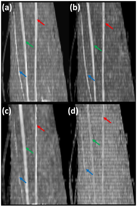
Based on the radiologist’s opinion, the FA maps with b = 1000 s/mm2provided the best results, in delineation and identification of the nerves. Therefore, all the results described below are based on this b value. Figure 1 shows oblique sagittal MIP images of FA maps of left forearm acquired with different spatial resolution, different number of diffusion gradient encoding directions and repetitions: spatial resolution (1×1 mm2), 42 DGED, and 2 repetitions (figure 1a); spatial resolution (1×1 mm2), 21 DGED, and 4 repetitions (figure 1b); spatial resolution (1.8×1.8 mm2), 42 DGED, and 2 repetitions (figure 1c); spatial resolution (1×1 mm2), 21 DGED, and 1 repetition (figure 1d). The superficial radial nerve in the low resolution images appear as a discontinued structure. The images with smaller number of repetitions even with higher spatial resolution did not clearly delineate the course of any of the nerves. In particular, the course of the superficial radial nerve appears discontinuous (Figure 1d). Visualization of the nerves was not affected by the number of DGED, provided adequate SNR was maintained by increasing the number of repetitions for scans with smaller number of DGED (Figure 1a and b). The DTI derived FA values obtained with various acquisition parameters (A, B, C, D, E, F, G, and H) are summarized in Tables 2 and 3. The p values based on the student’s t-test in which the FA values with different acquisition parameters are also included in these tables. The average FA value is highest for the lowest SNR (smaller number of DGED and averages). The FA value was observed to be smallest for the largest voxel size. In this comparison, we did not include the FA values of the superficial radial nerve since it was not visualized consistently at lower resolution and lower SNR.
Figure 1.
Oblique sagittal MIP images of FA maps of left forearm acquired with different spatial resolution, different number of diffusion gradient encoding directions (DGED) and repetitions: (a) spatial resolution (1×1 mm2), 42 DGED, and 2 repetitions; (b) spatial resolution (1×1 mm2), 21 DGED, and 4 repetitions; (c) spatial resolution (1.8×1.8 mm2), 42 DGED, and 2 repetitions; (d) spatial resolution (1×1 mm2), 21 DGED, and 1 repetition. The diffusion weighted images are acquired with 8 channel flexible small extremity coil. Median (green arrow), ulnar (red arrow) and superficial radial nerves (blue arrow).
Table 2.
Summary of FA values for the ulnar nerve acquired with different scan parameters.
| A | B | C | D | E | F | G | H | ||
|---|---|---|---|---|---|---|---|---|---|
| Spatial | 1×1 | 1×1 | 1×1 | 1×1 | 1×1 | 1×1 | 1×1 | 1.8×1.8 | |
| Resolution | |||||||||
| #DGED | 42 | 21 | 7 | 21 | 21 | 21 | 42 | 42 | |
| #repetitions | 2 | 4 | 12 | 4 | 2 | 1 | 2 | 2 | |
| FA | 0.746±0.031 | 0.762±0.037 | 0.786±0.050 | 0.762±0.037 | 0.772±0.046 | 0.797±0.062 | 0.746±0.037 | 0.699±0.045 | |
| A | p values | 0.04409 | 0.00031 | ||||||
| B | 0.02059 | ||||||||
| C | |||||||||
| D | 0.18405 | 0.00619 | |||||||
| E | 0.04650 | ||||||||
| F | |||||||||
| G | 0.00001 | ||||||||
| H |
The FA values were averaged over multiple measurements during optimization processes. The p values are based on the t-test in which the FA values with different acquisition schemes were compared.
A,B,C,D,E,F,G, and H indicate different acquisition conditions.
FA= Fractional Anisotropy
DGED= diffusion gradient encoding directions
p values=student’s t-test among different acquisition conditions, for example, p=0.04409 between A and B
Table 3.
Summary of FA values for the median nerve acquired with different scan parameters.
| A | B | C | D | E | F | G | H | ||
|---|---|---|---|---|---|---|---|---|---|
| Spatial | 1×1 | 1×1 | 1×1 | 1×1 | 1×1 | 1×1 | 1×1 | 1.8×1.8 | |
| Resolution | |||||||||
| #DGED | 42 | 21 | 7 | 21 | 21 | 21 | 42 | 42 | |
| #repetitions | 2 | 4 | 12 | 4 | 2 | 1 | 2 | 2 | |
| FA | 0.775±0.046 | 0.832±0.042 | 0.866±0.030 | 0.832±0.042 | 0.809±0.052 | 0.779±0.047 | 0.775±0.046 | 0.702±0.034 | |
| A | p values | 5.64E-06 | 1.82E-12 | ||||||
| B | 0.00039 | ||||||||
| C | |||||||||
| D | 0.03664 | 2.63E-05 | |||||||
| E | 0.01513 | ||||||||
| F | |||||||||
| G | 4.35E-09 | ||||||||
| H |
The FA values were averaged over multiple measurements during optimization processes. The p values are based on the t-test in which the FA values with different acquisition schemes were compared.
A, B, C, D, E, F, G, and H indicate different acquisition conditions.
FA= Fractional Anisotropy.
DGED= diffusion gradient encoding directions
p values=student’s t-test among different acquisition conditions, for example, p=0.04409 between A and B
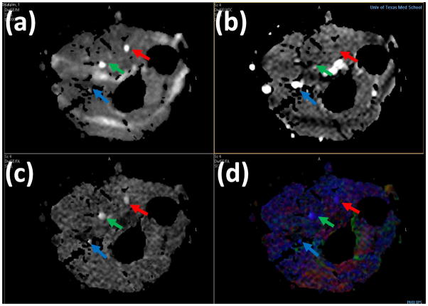
The DTI-derived maps are shown in Figure 2: (a) iso DWI (b) MD (c) gray scale FA (d) color FA of the left forearm in a control with median (green arrow), ulnar (red arrow) and superficial radial nerves (blue arrow). Blood in the MD map in Figure 2 (b) is seen as bright due to its higher MD compared to other tissues. Figure 2 (c) shows the gray scale FA map in which the median, ulnar, and superficial radial nerves can easily be identified. In the color coded FA shown in Figure 2 (d), red, green, and blue represent the directions along right-left, anterior-posterior, and superior-inferior, respectively.
Figure 2.
High resolution DTI derived maps: (a) iso DWI(b) MD (c) gray scale FA (d) color FA of the left forearm in a control. Median (green arrow), ulnar (red arrow) and superficial radial nerves (blue arrow).
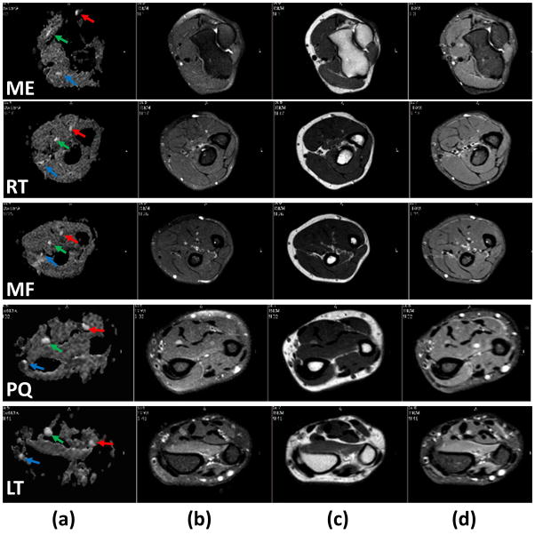
Axial T1- and T2-weighted with and without fat-suppression and STIR images at the five landmark locations are shown in Figure 3. In the axial plane, normal nerves have a smooth round or ovoid shape. In the T1-weighted MRI (Figure 3a), fat appears bright due to its short T1 and nerve appears isointense with the muscle. In the fat-suppressed T2-weighted images (Figure 3b), nerve appears with slightly higher intensity compared to the muscle. But in the non-fat suppressed T2-weighted images (Figure 3c), fat is brighter than other tissues, which can be used to measure the nerve size. In addition, a number of hyperintense structures are also visible on this image. Similar to the T2-weighted image, the STIR image (Figure 3d) shows vessels as bright, while the intensity of nerves is intermediate between vessels and muscle. In these images, the hypointense structures on the T1-weighed images and of variable signal intensity on the T2-weighed images represent vessels. As can be seen from both Figures 2 and 3, nerves are the most conspicuous structures on the FA maps.
Figure 3.
Comparison of axial grey scale FA map (first column), fat-suppressed (FS) T2-weighted (second column), T2-weighted without fat suppression (third column), and STIR (Fourth column) at the levels of medial epicondyle (first row), radial tuberosity (second row), middle forearm (third row), pronator quadratus proximal margin (fourth row), and Lister’s tubercle (fifth row) obtained from the forearm of a healthy control. The superior contrast and improved conspicuity of the FA map allows easy identification of median (green arrow), ulnar (red arrow), and superficial radial (blue arrow) nerves compared to other images.
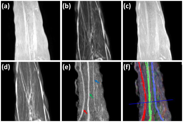
Figure 4 shows typical sagittal MIP images reconstructed from T1- and T2-weighted, STIR, and FA images, along with the fiber tracks superposed on the FA MIP images. In the STIR and T2-weighted MIP images the other structures such as vessels with hyperintensity impede clear delineation of the nerves. In the T1-and T2- weighted (without FatSat) MIP image, the background fat signal dominates and continuity of the nerve is not observed. Notably, the MIP FA image provides superior contrast for unequivocal identification of median, ulnar and superficial radial nerves. Figure 4f shows the fiber tracking of these nerves and they matched the course of the nerves on the MIP images. In this figure, the median, ulnar, and superficial radial nerves are coded in green, red, and blue, respectively.
Figure 4.
Comparison of MIP images derived from: (a) T1-weighted(b) FS T2-weighted (c) T2-weighted (d) STIR, (e) FA maps, and (f) 3D fiber tractography of median nerve (green), ulnar nerve (red) and superficial radial (blue) superposed on FA MIP, of the left forearm in a control. It is very difficult to identify the nerves on images a, b, c and d. However, the FA map provided much better delineation for easy identification of median (green arrow), ulnar (red arrow), and superficial radial nerves (blue), and fiber tracts show excellent correlation with the FA MIP images.
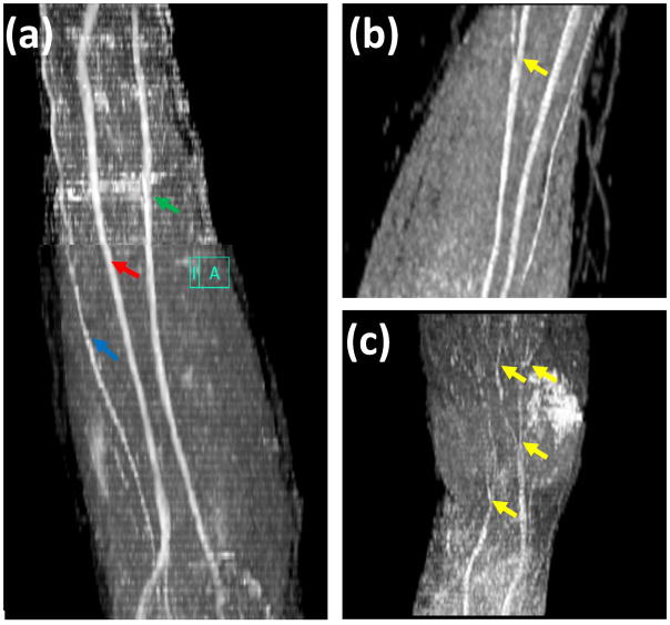
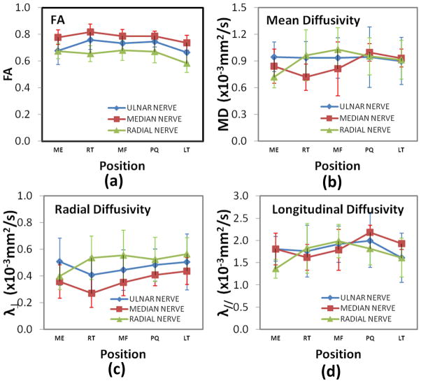
The oblique sagittal MIP FA map for the whole forearm (elbow to wrist) is shown in Figure 5a. Because of the tortuous course of nerves it is not possible to visualize the nerve branches in a single orientation or at a single level. Figures 5b (elbow to middle of the forearm) and 5c (around the wrist area) show the nerve branches clearly on the sagittal FA maps. The spatial variations of the average FA, MD, λ// and λ⊥ values from ten subjects at five landmarks are shown in Figure 6. The DTI-derived measures of all the three nerves showed significant spatial dependence except FA values based on the student’s t-test.
Figure 5.
Oblique sagittal MIP image of FA maps (a), large nerve branch (b), and small nerve branches (c), of left forearm, high spatial resolution DTI imaging with 8 channel flexible small extremity coil and 42 diffusion-encoding gradient directions. High spatial resolution DTI imaging allows improved visualization of nerves, median (green arrow), ulnar (red arrow), superficial radial nerves (blue arrow), and nerve branches (yellow).
Figure 6.
Spatial variation of (a) FA, (b) MD, (c) // and (d) ⊥ for the ulnar, median, and superficial radial nerves from left forearm in a normal volunteer at different levels.
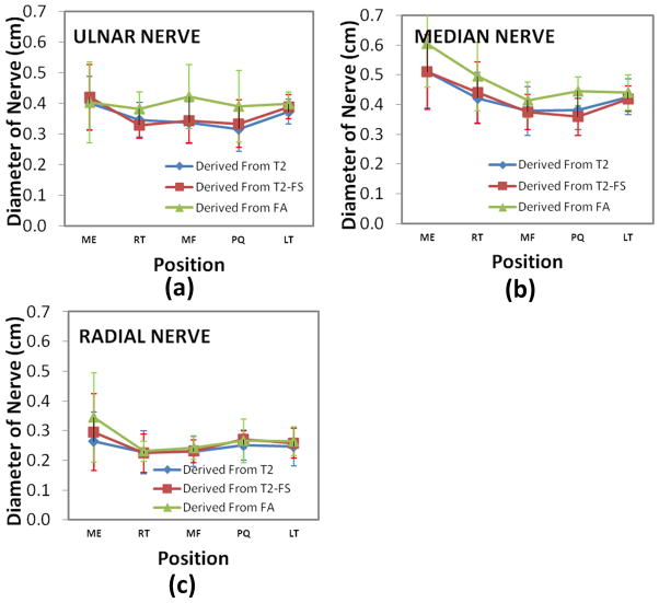
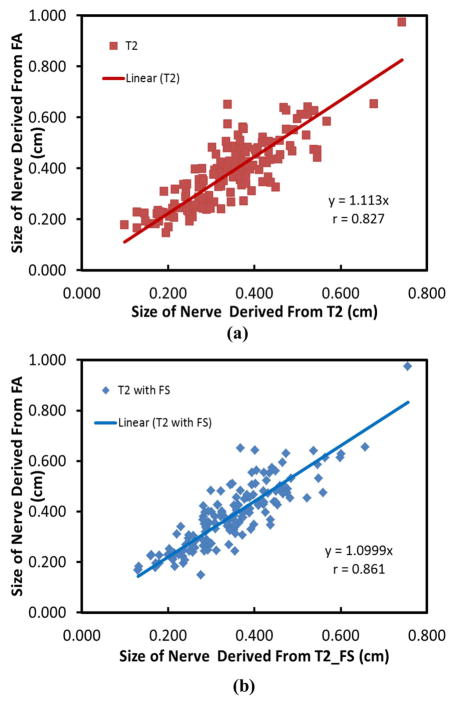
Figure 7 shows the results of the nerve diameter (average ±standard deviation) at five locations, averaged over the ten subjects. The nerve size at medial epicondyle is thickest among all the five locations. Figure 8 shows the correlation between the sizes of the three nerves measured by FA maps and those determined by T2-weighted images at different locations for all the ten subjects. The r values for these correlations are 0.827 (T2-weighted) and 0.861 (T2-weighted with FatSat) indicating a good agreement between the nerve size derived from FA and T2-weighted images.
Figure 7.
Average nerve diameter of the ulnar (a), median (b), and superficial radial nerves (c), from left forearm in ten normal volunteer at different levels.
Figure 8.
Correlation of nerve diameters between measurements from T2 and FA maps (a), and T2 with FatSat and FA maps (b). Data was collected from the ulnar, median and superficial radial nerves and five locations for each nerve.
Discussion
The DTI scanning parameters were varied systemically to obtain the best image quality as evaluated by a radiologist with significant experience in this area. We believe, for the first time all the three forearm nerves and some of their branches on the FA maps were visualized that could help in detecting and objectively monitoring the progression of PNS pathology. Our results show that FA maps are superior to other sequences in visualizing peripheral nerves without interference from vessels and other tissues (figure 3). MIP images of FA maps and fiber tractography allowed clear delineation of the course of the nerves (figure 4). Previous DTI studies on peripheral nerves have generally focused on a specific nerve at specific locations (8–10, 12, 16) or acquired at a relatively low spatial resolution (17).
Our optimization studies show that both SNR and spatial resolution play an important role in visualizing the peripheral nerves. While the protocol is developed for imaging the forearm nerves, it can be easily extended to imaging peripheral nerves in other extremities. We have also determined various MRI-derived measures of ulnar, median, and superficial radial nerves at multiple locations that have the potential to play an important role in identification, quantification, and serial assessment of nerve pathology in the human forearm.
T1-weighted, T2–weighted with and without FatSat, and STIR Imaging
As indicated earlier, combination of high resolution T1-weighted images and heavily T2-weighted images with/without fat suppressed or STIR images are currently used for MRN. T1-weighted imaging is used to define the bony structures and tissues surrounding the nerves. Smaller peripheral nerves with lower fat in the neurovascular bundle are barely discernible on standard T1-weighted images. In the fat saturated T2-weighted and STIR images, the fat signal is suppressed to enhance the nerve signal. The additional REST (REgional Saturation Technique) bands help suppress the surrounding fatty tissues. STIR generally outperforms frequency selective fat saturation with respect to homogeneity of signal suppression by maintaining the quality of fat suppression even if the arm is away from the center of the magnet. Advantages of T2-based imaging include relative simplicity of protocol design and execution, reproducibility, proven validity, and radiologists’ familiarity.
High Resolution DTI Imaging
The FA maps at higher spatial resolution, acquired with the optimized DTI scan parameters allowed visualization of the superficial radial, median, and ulnar nerves consistently on all the scans, whereas only ulnar and median nerves were clearly visualized at lower spatial resolution (17). We believe that our studies are the first to systematically evaluate the effect of various acquisition parameters on the visualization and quantification of the diffusion anisotropy in peripheral nerves. This is confirmed by both theoretical and experimental studies (20, 23, 24) that have investigated the effects of SNR, number of DGED, and spatial resolution on quantification of FA in human brain. For the protocol with larger DGED, more DW images were acquired but with less averaging for each DW image to keep the same SNR. Our results indicate the visualization of the diffusion anisotropy of forearm nerves is strongly influenced by the SNR and spatial resolution. The acquisition time can be further reduced by using less number of slices and only focusing on the injured areas in real clinical applications. Another way to reduce the scan time was to user fewer number of diffusion encoding directions. However, this will result in lower SNR and compromised angular resolution. The reduction of DGED will decrease the SNR and angular resolution. In the case of high SNR, both 21 and 42 gradient directions performed well. We did not investigate the effect of other gradient direction values. Our results also suggest that smaller number of encoding directions and low SNR bias the estimation of FA values. For example, the FA value of the nerves obtained with lowest SNR (as indicated by the smallest number of averages and DGEDs) has the highest FA value. Our results are also consistent with other reports that demonstrate the importance of acquisition parameters for improved estimation of diffusion tensor (Table 2 and 3). For example, a recent intra-subject spinal cord study indicated that the value of FA varied with the number of DGED, number of averages, and spatial resolution (25). We observed lowest FA with the largest voxel size. This may be the result of partial volume averaging where the surrounding tissue has lower FA than the nerve. A brain DTI study demonstrated that spatial resolution can directly affect the accuracy of FA (26).
Since the nerve diameter is an important measure of pathology, we compared the nerve diameter determined on the T2-weighted (with and without FatSat) images and the FA maps. It has been reported that the nerve size on the FA maps acquired at low resolution tends to be 1.5~2.0 times larger than the one observed on the T2-weighted images (17). We hypothesized that this discrepancy may be the result of partial volume averaging in the DTI data acquired at relatively low resolution. In this high resolution DTI study, strong correlation is observed between the nerve size derived from FA maps and from the T2-weighted images. These results suggest that high spatial resolution DTI protocols are more reliable in estimating the nerve size.
In conclusion, consistent visualization of median, ulnar, superficial radial nerves and their branches is possible with optimized high spatial resolution DTI. Strong correlation is observed between the nerve size derived from FA maps and the T2- weighted images; Quantitative DTI measures such as FA, MD, λ//, and λ⊥ provide normative values for comparison with the diseased/injured nerves to assess nerve integrity and repair.
Acknowledgments
This work is supported in part by the NINDS/NIH grant # NS070888-01 awarded to KAS and NCRR/NIH grant # S10 RR17205 awarded to PAN.
References
- 1.Kim SJ, Hong SH, Jun WS, et al. MR imaging mapping of skeletal muscle denervation in entrapment and compressive neuropathies. Radiographics. 2011;31:319–332. doi: 10.1148/rg.312105122. [DOI] [PubMed] [Google Scholar]
- 2.Subhawong TK, Wang KC, Thawait SK, et al. High resolution imaging of tunnels by magnetic resonance neurography. Skeletal Radiol. 2012;41:15–31. doi: 10.1007/s00256-011-1143-1. [DOI] [PMC free article] [PubMed] [Google Scholar]
- 3.Stoll G, Bendszus M, Perez J, Pham M. Magnetic resonance imaging of the peripheral nervous system. J Neurol. 2009;256:1043–1051. doi: 10.1007/s00415-009-5064-z. [DOI] [PubMed] [Google Scholar]
- 4.Andreisek G, Crook DW, Burg D, Marincek B, Weishaupt D. Peripheral neuropathies of the median, radial, and ulnar nerves: MR imaging features. Radiographics. 2006;26:1267–1287. doi: 10.1148/rg.265055712. [DOI] [PubMed] [Google Scholar]
- 5.Howe FA, Filler AG, Bell BA, Griffiths JR. Magnetic resonance neurography. Magn Reson Med. 1992;28:328–338. doi: 10.1002/mrm.1910280215. [DOI] [PubMed] [Google Scholar]
- 6.Kuntz C, Blake L, Britz G, et al. Magnetic resonance neurography of peripheral nerve lesions in the lower extremity. Neurosurgery. 1996;39:750–756. doi: 10.1097/00006123-199610000-00021. [DOI] [PubMed] [Google Scholar]
- 7.Smith AB, Gupta N, Strober J, Chin C. Magnetic resonance neurography in children with birth-related brachial plexus injury. Pediatr Radiol. 2008;38:159–163. doi: 10.1007/s00247-007-0665-0. [DOI] [PubMed] [Google Scholar]
- 8.Jambawalikar S, Baum J, Button T, Li H, Geronimo V, Gould ES. Diffusion tensor imaging of peripheral nerves. Skeletal Radiol. 2010;39:1073–1079. doi: 10.1007/s00256-010-0974-5. [DOI] [PubMed] [Google Scholar]
- 9.Meek MF, Stenekes MW, Hoogduin HM, Nicolai JP. In vivo three-dimensional reconstruction of human median nerves by diffusion tensor imaging. Exp Neurol. 2006;198:479–482. doi: 10.1016/j.expneurol.2005.12.014. [DOI] [PubMed] [Google Scholar]
- 10.Stein D, Neufeld A, Pasternak O, et al. Diffusion tensor imaging of the median nerve in healthy and carpal tunnel syndrome subjects. J Magn Reson Imaging. 2009;29:657–662. doi: 10.1002/jmri.21553. [DOI] [PubMed] [Google Scholar]
- 11.Andreisek G, White LM, Kassner A, Sussman MS. Evaluation of diffusion tensor imaging and fiber tractography of the median nerve: preliminary results on intrasubject variability and precision of measurements. AJR Am J Roentgenol. 2010;194:W65–W72. doi: 10.2214/AJR.09.2517. [DOI] [PubMed] [Google Scholar]
- 12.Kabakci N, Gurses B, Firat Z, et al. Diffusion tensor imaging and tractography of median nerve: normative diffusion values. AJR Am J Roentgenol. 2007;189:923–927. doi: 10.2214/AJR.07.2423. [DOI] [PubMed] [Google Scholar]
- 13.Lehmann HC, Zhang J, Mori S, Sheikh KA. Diffusion tensor imaging to assess axonal regeneration in peripheral nerves. Exp Neurol. 2010;223:238–244. doi: 10.1016/j.expneurol.2009.10.012. [DOI] [PMC free article] [PubMed] [Google Scholar]
- 14.Sheikh KA. Non-invasive imaging of nerve regeneration. Exp Neurol. 2010;223:72–76. doi: 10.1016/j.expneurol.2009.07.008. [DOI] [PMC free article] [PubMed] [Google Scholar]
- 15.Skorpil M, Karlsson M, Nordell A. Peripheral nerve diffusion tensor imaging. Magn Reson Imaging. 2004;22:743–745. doi: 10.1016/j.mri.2004.01.073. [DOI] [PubMed] [Google Scholar]
- 16.Kabakci NT, Kovanlikaya A, Kovanlikaya I. Tractography of the median nerve. Semin Musculoskelet Radiol. 2009;13:18–23. doi: 10.1055/s-0029-1202241. [DOI] [PubMed] [Google Scholar]
- 17.Zhou Y, Kumaravel M, Patel VS, Sheikh KA, Narayana PA. Diffusion tensor imaging of forearm nerves in humans. J Magn Reson Imaging. 2012;36:920–927. doi: 10.1002/jmri.23709. [DOI] [PMC free article] [PubMed] [Google Scholar]
- 18.Hiltunen J, Kirveskari E, Numminen J, Lindfors N, Goransson H, Hari R. Pre- and post-operative diffusion tensor imaging of the median nerve in carpal tunnel syndrome. Eur Radiol. 2012;22:1310–1319. doi: 10.1007/s00330-012-2381-x. [DOI] [PubMed] [Google Scholar]
- 19.Andreisek G, White LM, Kassner A, Tomlinson G, Sussman MS. Diffusion tensor imaging and fiber tractography of the median nerve at 1. 5T: optimization of b value. Skeletal Radiol. 2009;38:51–59. doi: 10.1007/s00256-008-0577-6. [DOI] [PubMed] [Google Scholar]
- 20.Landman BA, Farrell JA, Jones CK, Smith SA, Prince JL, Mori S. Effects of diffusion weighting schemes on the reproducibility of DTI-derived fractional anisotropy, mean diffusivity, and principal eigenvector measurements at 1. 5T. Neuroimage. 2007;36:1123–1138. doi: 10.1016/j.neuroimage.2007.02.056. [DOI] [PMC free article] [PubMed] [Google Scholar]
- 21.Santarelli X, Garbin G, Ukmar M, Longo R. Dependence of the fractional anisotropy in cervical spine from the number of diffusion gradients, repeated acquisition and voxel size. Magn Reson Imaging. 2010;28:70–76. doi: 10.1016/j.mri.2009.05.046. [DOI] [PubMed] [Google Scholar]
- 22.Basser PJ, Pierpaoli C. Microstructural and physiological features of tissues elucidated by quantitative-diffusion-tensor MRI. J Magn Reson B. 1996;111:209–219. doi: 10.1006/jmrb.1996.0086. [DOI] [PubMed] [Google Scholar]
- 23.Lagana M, Rovaris M, Ceccarelli A, Venturelli C, Marini S, Baselli G. DTI parameter optimisation for acquisition at 1.5T: SNR analysis and clinical application. Comput Intell Neurosci. 2010:254032. doi: 10.1155/2010/254032. [DOI] [PMC free article] [PubMed] [Google Scholar]
- 24.Gao W, Zhu H, Lin W. A unified optimization approach for diffusion tensor imaging technique. Neuroimage. 2009;44:729–741. doi: 10.1016/j.neuroimage.2008.10.004. [DOI] [PMC free article] [PubMed] [Google Scholar]
- 25.Santarelli X, Garbin G, Ukmar M, Longo R. Dependence of the fractional anisotropy in cervical spine from the number of diffusion gradients, repeated acquisition and voxel size. Magn Reson Imaging. 2010;28:70–76. doi: 10.1016/j.mri.2009.05.046. [DOI] [PubMed] [Google Scholar]
- 26.Kim M, Ronen I, Ugurbil K, Kim DS. Spatial resolution dependence of DTI tractography in human occipito-callosal region. Neuroimage. 2006;32:1243–1249. doi: 10.1016/j.neuroimage.2006.06.006. [DOI] [PubMed] [Google Scholar]


