

Abstract
We have designed two metal–organic frameworks (MOFs) to efficiently convert X-ray to visible-light luminescence. The MOFs are constructed from M6(μ3-O)4(μ3-OH)4(carboxylate)12 (M = Hf or Zr) secondary building units (SBUs) and anthracene-based dicarboxylate bridging ligands. The high atomic number of Zr and Hf in the SBUs serves as effective X-ray antenna by absorbing X-ray photons and converting them to fast electrons through the photoelectric effect. The generated electrons then excite multiple anthracene-based emitters in the MOF through inelastic scattering, leading to efficient generation of detectable photons in the visible spectrum. The MOF materials thus serve as efficient X-ray scintillators via synergistic X-ray absorption by the metal-cluster SBUs and optical emission by the bridging ligands.
X-ray scintillators are widely used in X-ray dosimetry and imaging. Sensitive detection of X-rays reduces the patient exposure while maintaining or improving the image quality. A number of solid-state inorganic materials with lanthanides as light emitters, such as LaOBr:Tm, Gd2O2S:Tb, and M′-YTaO4,1,2 have been developed as efficient X-ray-to-light convertors. Nanophosphors have also been employed as molecular probes for a dual modality X-ray and optical imaging, referred to as X-ray luminescence3 computed tomography (XLCT).4−6 By taking advantage of long penetration depth of X-ray and low optical autofluorescence background, XLCT promises to provide a highly sensitive molecular imaging technique. Additionally, nanoparticles based on solid-state scintillators have been attached with singlet oxygen sensitizers for X-ray induced photodynamic therapy (PDT).7−9
Organic crystals such as anthracene can also serve as radiation scintillators, particularly for detecting low-energy β-rays and neutrons due to their high scattering cross sections for electron and neutron and low rates of backscattering.10−13 Organic scintillators are however ineffective for X-ray detection (<100 keV) due to their low X-ray scattering cross sections. Metal–organic frameworks (MOFs) are a class of crystalline materials that are built from well-defined molecular bridging ligands and metal/metal cluster connecting nodes.14−28 MOFs thus provide a tunable platform for the co-assembly of organic scintillator molecules and metal cluster nodes of high atomic numbers (Z) within a highly ordered structure.29 Allendorf et al. have examined several Zn MOFs for radioluminescence induced by fast proton, neutron, electron, and γ-rays.30,31 They observed enhanced stability of MOF-based scintillators to radiation damage when compared to corresponding organic scintillators, presumably due to the spatial separation of scintillator molecules in MOFs.32−34 In a densely packed crystal, excitations can become delocalized and migrate within the crystal. As the defect sites resulted from radiation damage slowly accumulate, the delocalized excitons can travel to the defect sites via random walk and be efficiently quenched. In contrast, site separations in open frameworks reduce the mobility of excitons, making the luminescent sensing performance of the material more resilient to radiation damage. The internal cavity of MOFs is also suitable for loading therapeutic agents for the development of multifunctional theranostic systems. (35) MOFs have however not been reported to exhibit X-ray induced luminescence, due to relatively small X-ray scattering cross sections of the majority of MOFs that are built from first-row transition-metal connecting nodes.
Here, we synthesized MOFs with high Z metal clusters M6(μ3-O)4(μ3-OH)4(carboxylate)12 (M = Hf or Zr) as connecting nodes and an anthracene-based emitter as the bridging ligand (Scheme 1). With Z = 72 for Hf and Z = 40 for Zr, they serve as efficient X-ray absorbers. Upon photoelectric absorption of X-rays in the 20–200 keV range, outer-shell electrons of Hf4+ and Zr4+ ions are ejected as fast electrons which interact with the anthracene-based linkers to generate luminescence signals from their electronic excited states. The high Z metal clusters and emissive bridging ligands thus work synergistically to lead to highly efficient X-ray induced luminescence in the easily detectable visible spectrum.
Scheme 1. (a) Synthesis of Hf-MOF and Zr-MOF and (b) Scheme Showing X-ray Induced Generation of Fast Photoelectrons from Heavy Metals Followed by Scintillation of the Anthracene-Based Linkers in the Visible Spectrum.
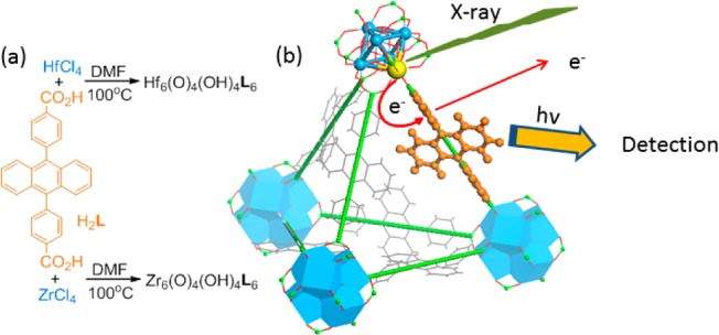
We targeted the synthesis of UiO frameworks (Hf-MOF and Zr-MOF) built from a linear dicarboxylate ligand and the M6(μ3-O)4(μ3-OH)4(carboxylate)12 SBU (M = Hf or Zr) because of their high chemical stability and structural predictability.36−39 The 9,10-anthacenyl bis(benzoic acid) (H2L) was prepared in a high yield following a literature procedure.40Hf-MOF and Zr-MOF were synthesized by treating H2L with HfCl4 or ZrCl4 in DMF at 100 °C for 2 days (Scheme 1). The resulting white crystalline solids were washed with copious amounts of DMF, methanol, and water. The crystal structures of these two MOFs were revealed by the similarities of their PXRD patterns to the simulated pattern from a UiO MOF that is built from the amino-terphenyldicarboxylate ligand of the same length as L (Figure 1).38 Both MOFs adopt the UiO framework structure of the fcu topology by connecting the M6(μ3-O)4(μ3-OH)4(carboxylate)12 SBU with the linear L linkers (Figure 1a,b). Within every SBU, M4+ was placed on the six cortexes of an octahedron. The faces of the octahedron were bridged by a μ3-O2– or a μ3-OH– alternately. The edges of the octahedron were bridged by a carboxylate group with each oxygen coordinating to one M4+, finishing an eight-coordinated environment for each M4+ ion (Figure 1c). Because of the steric bulk of the L ligand, noninterpenetrated structures were obtained based on systematic absences of the PXRD patterns (Figures 2c and S4).41 The open-framework possesses a 60.5% void space, as calculated by PLATON42 and a triangular open channel with 1.2 nm edge length. For every SBU, there are one octahedral cavity with a diameter of 0.8 nm and two tetrahedral cavities with a diameter of 0.6 nm (Figure 1d,e). TEM and SEM images of Hf-MOF and Zr-MOF showed octahedral microcrystals of ∼1 μm in dimensions (Figures 2a,b and Figure S3). Nitrogen adsorption measurements on the MOFs gave BET surface areas of 2187 and 2776 m2/g for Hf-MOF and Zr-MOF, respectively (Figure 2d). The pore-size distribution functions of both MOFs showed maxima at around 0.6, 0.8, and 1.2 nm (Figure S2), consistent with the cavity and channel sizes derived from the crystal structural models.
Figure 1.
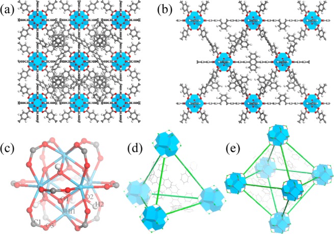
Structural models of Hf-MOF and Zr-MOF. Structures viewed from the (a) [100] and (b) [110] directions. (c) Ball–stick model of M6(μ3-O)4(μ3-OH)4(carboxylate)12 (M = Hf or Zr) SBU. (d) Tetrahedral and (e) Octahedral cavities. Blue polyhedra: Hf4+ or Zr4+ with eight coordinating oxygen atoms; red ball: oxygen; gray ball: carbon; white ball: hydrogen.
Figure 2.
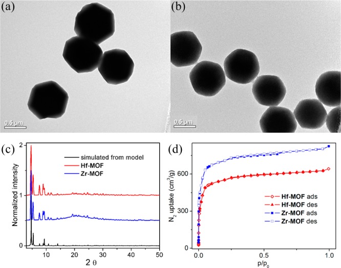
TEM images of (a) Hf-MOF and (b) Zr-MOF. (c) PXRD patterns of Hf-MOF (red) and Zr-MOF (blue) along with the simulated pattern. (d) N2 adsorption and desorption curves at 77 K for Hf-MOF (red) and Zr-MOF (blue).
Fluorescence spectra of suspensions of Hf-MOF (0.04 mM of L ligand) in water, DMF, and THF were taken with an excitation wavelength of 368.8 nm (Figures 3a, S5, and S7). The maxima of the emission spectra shift to longer wavelengths as the polarity of the solvent increases (430 nm in THF, 435 nm in DMF, and 469 nm in water, Figure S9), as predicted by the general solvent effect.43 Such an observation supports the accessibility of the anthracene sites in the MOFs to solvent molecules. The excitation spectra of the MOFs in more polar solvents also exhibit less defined vibrational fine structure due to stronger coupling of the solvent bath modes to the molecular electronic and vibrational coordinates (Figures 3a, S5, and S7). Suspensions of Zr-MOF (0.04 mM of L ligand) in water and DMF showed similar emission spectra as Hf-MOF (Figures 3a and S5). In contrast, H2L particles which are insoluble in water showed only moderate dependence of emission on solvent (Figure S10), due to the inability of solvent molecules to access the interiors of the ligand particles. Fluorescence lifetimes of Hf-MOF, Zr-MOF, and H2L suspensions in water were also examined. All of the suspended samples showed bi-exponential fluorescence decays, and the weighted lifetimes of the samples were calculated based on the fittings (Table S1). Hf-MOF and Zr-MOF possess significantly longer lifetimes (6.19 and 5.96 ns, respectively, Figure 3b) than H2L particles (2.0 ns, Figure S11). This difference probably results from a combination of a solvent effect on excited-state lifetime and the exciton migration in the densely packed H2L particles. The mobile excited state can move and be trapped and quenched at a defect site in a H2L particle, while site isolation of anthracene moieties in the MOFs reduces the excited-state mobility, leading to an enhanced lifetime of the excited state. Consistent with this, the DMF solution of H2L exhibits longer excited state lifetimes (5.34 ns) than those of DMF suspensions of Hf-MOF (4.06 ns) and Zr-MOF (3.92 ns) (Figures S6 and S11). Previous studies indicated that the free rotation of anthracene in the structure can reduce its luminescence signal. Such effect needs to be considered for a full evaluation of the luminescent properties of the MOFs.31
Figure 3.
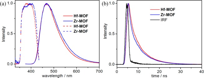
(a) Fluorescence spectra of Hf-MOF (red, solid), Zr-MOF (blue, solid), and H2L ligand (insoluble particle, black, solid) suspensions in water (0.04 mM L) excited at a wavelength of 368.8 nm. The corresponding excitation spectra monitored at 469 nm are shown in dashed lines. (b) Time-dependent fluorescence decay traces of Hf-MOF (red), Zr-MOF (blue), and H2L ligand (black) suspensions in water excited at 368.8 nm and monitored at 469 nm, together with instrument response function (IRF, gray).
We proposed that the heavy metal clusters in the MOF structure could serve as an effective X-ray antenna due to their high Z numbers. The outer-shell electrons of Hf4+ and Zr4+ ions are ejected as fast electrons upon the X-ray absorption through the photoelectric effect. The generated photoelectrons then experience inelastic scattering in a framework and transfer their energy to the L ligands, bringing them to excited states which decay and emit the visible photons for detection (Scheme 1b). X-ray luminescence of the MOF particles (200 μL suspensions in water) were tested with clinical superficial therapy system. Both Hf-MOF and Zr-MOF exhibit bright radioluminescence in the visible spectrum upon X-ray excitation (Figure 4a).
Figure 4.
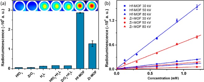
(a) Radioluminescence signals of Hf-MOF, Zr-MOF, and control samples (from left to right): HfO2 and ZrO2 colloidal nanoparticles, H2L alone, H2L + HfO2 colloid, H2L + ZrO2 colloid, Hf-MOF, and Zr-MOF. The concentrations of H2L or Hf or Zr in the samples are 1.2 mM. The X-ray dosages are 1 Gy/10 s with effective X-ray energy ∼18.9 keV (40 kV tube voltage, 0.08 mA tube current) and detection gain of 200. (b) Radioluminescence signals of Hf-MOF and Zr-MOF with different concentrations and different radiation tube voltages.
As expected, Hf-MOF exhibited higher radioluminescence signal than Zr-MOF under the same experimental conditions due to higher X-ray scattering cross section of Hf than Zr (e.g., the average energy attenuation coefficient ranges for Hf from ∼110 to 18 cm2/g and for Zr ∼ 23 to 16 cm2/g in the 15–30 keV range).44 As control experiments, neither the anthracenyl ligand H2L by itself nor metal oxide (HfO2 or ZrO2) nanoparticles produce significant amount of optical signal, indicating the important synergistic roles played by both heavy metal antenna and organic emitters in the MOF assemblies. Hf-MOF (1.2 mM L or Hf) produced a signal that is ∼24 times of the signal generated by H2L alone, while the Zr-MOF produced as signal of ∼11 times the amount. For comparison, the widely used inorganic scintillator NaI(Tl) has a light output of 2.3 times of that of the anthracene crystal, while practical organic liquid and plastic scintillators all have lower light outputs than the anthracene crystal.45 In contrast, a physical mixture of colloidal metal oxide (HfO2 or ZrO2) and ligand H2L only generates luminescence slightly higher than that of H2L (∼1.3 times for HfO2 + H2L and ∼1.2 times for ZrO2 + H2L). Additional control experiments with HfOCl2 and ZrOCl2 solutions and Me2L (methyl ester of the L ligand) were also performed (Figure S14). Again negligible luminescence was generated by the solution samples as compared to that of the MOF samples.
Radioluminescence of MOF suspensions in ethanol was also measured with slightly lower luminescence as compared to that obtained in aqueous solution under the same experimental condition (Figure S15). Such solvent dependence indicates the importance of interactions between solvent molecules and the generated fast electrons which determine the overall X-ray-to-photon conversion efficiency. To eliminate the solvent effect, we measured the radioluminescence of dry MOF samples in the absence of any solvent molecules (Figure S16). We have to use ∼15 times more MOFs than those used in suspension measurements, to get sufficient volumes of the materials for the measurements. The resulting luminescence signals of the MOFs are ∼1200 times more intense for the Hf-MOF and ∼2400 times more intense for the Zr-MOF than those signals obtained from aqueous suspensions. Note that we need to decrease the integration time (or dosage) of the measurement from 10 to 0.01 s and reduce the detection gain from 200 to 50 to avoid saturating the detector. Although it is difficult to quantitatively compare the results from solid samples and those from suspensions, we can at least qualitatively conclude that the solid samples can generate much more (80 to 160 times) radioluminescence in the absence of solvent molecules, consistent with a secondary fast electron induced luminescence as the major mechanism of X-ray to visible light conversion.
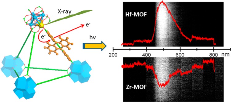
Different concentrations of Hf-MOF and Zr-MOF samples in aqueous suspensions were exposed to X-rays with effective energies of 14.8, 16.2, and 29.8 keV (with the delivered dose of ∼0.025, 0.25, and 0.05 Gy per 10 s based on the tube voltage of 30, 50, and 80 kV and the tube current 7.6, 30, and 8 mA) for a further systematic study. As shown in Figure 4b, the observed radioluminescence signals of MOFs vary linearly with the nanoparticle concentrations for all the three X-ray energies. It was also confirmed that increase of dose leads to the increase of signal from MOFs; the more X-ray photons absorbed, the more visible photons generated. The spectrum of X-ray induced luminescence from these MOF samples was measured with a custom-made system (SI). Samples showed radioluminesecnce peaks ranging between 400 and 600 nm (Figure 5), similar to the optical fluorescence spectrum shown in Figure 3. Optical stability of the radioluminescence against X-ray damage was also examined (SI). The cumulative dose of up to 300 Gy was delivered to Zr-MOF and Hf-MOF samples, and X-ray luminescence was examined by very low-dose X-ray irradiation (∼0.25 μGy) before and after ultrahigh-dose delivery. No substantial decrease of the X-ray induced luminescence was observed (Figure S17).
Figure 5.
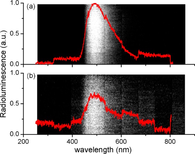
Optical spectra of (a) Hf-MOF and (b) Zr-MOF induced by X-ray irradiation at a dose of 6 Gy/min. Spectra were recorded using an EM-CCD with the Lightfield software.
In summary, two X-ray scintillating MOFs based on Hf and Zr clusters and anthracene-based bridging ligands as emitters have been designed and synthesized. The resultant MOF materials exhibit superior X-ray-to-light converting capabilities compared to the components themselves, thanks to a synergistic function of heavy SBUs as X-ray antenna and of bridging ligands as light emitters. This work highlights the opportunity of designing highly efficient sensory materials by taking advantage of the ability to synergistically integrate multiple functionalities into MOFs.
Acknowledgments
We thank NIH (UO1-CA151455 to W.L. and 1R01-EB016618 to L.X.) for funding support. We would like to acknowledge Dr. Benjamin Fahimian from Stanford Cancer Center for his help with the use of True Beam System (linear accelerator).
Supporting Information Available
Experimental details and data. This material is available free of charge via the Internet at http://pubs.acs.org.
Author Contributions
§ C.W. and O.V. contributed equally.
The authors declare no competing financial interest.
Funding Statement
National Institutes of Health, United States
Supplementary Material
References
- Nikl M. Measurement Sci. Technol. 2006, 17, R37. [Google Scholar]
- Issler S. L.; Torardi C. C. J. Alloy. Comp. 1995, 229, 54. [Google Scholar]
- Here X-ray luminescence refers to generation of photons with visible optical frequency upon X-ray excitation. It is distinct from the X-ray fluorescence, in which a secondary X-ray photon of lower energy is generated and detected upon excitation of X-ray with higher energy.
- Pratx G.; Carpenter C. M.; Sun C.; Rao R. P.; Xing L. Opt. Lett. 2010, 35, 3345. [DOI] [PMC free article] [PubMed] [Google Scholar]
- Ale A.; Ermolayev V.; Herzog E.; Cohrs C.; de Angelis M. H.; Ntziachristos V. Nat. Meth. 2012, 9, 615. [DOI] [PubMed] [Google Scholar]
- Sun C.; Pratx G.; Carpenter C. M.; Liu H.; Cheng Z.; Gambhir S. S.; Xing L. Adv. Mater. 2011, 23, H195. [DOI] [PMC free article] [PubMed] [Google Scholar]
- Chen W.; Zhang J. J. Nanosci. Nanotechnol. 2006, 6, 1159. [DOI] [PubMed] [Google Scholar]
- Scaffidi J. P.; Gregas M. K.; Lauly B.; Zhang Y.; Vo-Dinh T. ACS Nano 2011, 5, 4679. [DOI] [PubMed] [Google Scholar]
- Liu Y. F.; Chen W.; Wang S. P.; Joly A. G. Appl. Phys. Lett. 2008, 92, 043901. [Google Scholar]
- Clarke H. B.; Northrop D. C.; Simpson O. Proc. Phys. Soc. 1962, 79, 366. [Google Scholar]
- Gibbons P. E.; Northrop D. C.; Simpson O. Proc. Phys. Soc. 1962, 79, 373. [Google Scholar]
- Im H. J.; Saengkerdsub S.; Stephan A. C.; Pawel M. D.; Holcomb D. E.; Dai S. Adv. Mater. 2004, 16, 1757. [Google Scholar]
- Kesanli B.; Hong K.; Meyer K.; Im H. J.; Dai S. Appl. Phys. Lett. 2006, 89, 214104. [Google Scholar]
- Kitagawa S.; Kitaura R.; Noro S. Angew. Chem., Int. Ed. Engl. 2004, 43, 2334. [DOI] [PubMed] [Google Scholar]
- Ferey G.; Mellot-Draznieks C.; Serre C.; Millange F. Acc. Chem. Res. 2005, 38, 217. [DOI] [PubMed] [Google Scholar]
- Long J. R.; Yaghi O. M. Chem. Soc. Rev. 2009, 38, 1213. [DOI] [PubMed] [Google Scholar]
- Farha O. K.; Hupp J. T. Acc. Chem. Res. 2010, 43, 1166. [DOI] [PubMed] [Google Scholar]
- Tanabe K. K.; Cohen S. M. Chem. Soc. Rev. 2011, 40, 498. [DOI] [PubMed] [Google Scholar]
- Eddaoudi M.; Kim J.; Rosi N.; Vodak D.; Wachter J.; O’Keeffe M.; Yaghi O. M. Science 2002, 295, 469. [DOI] [PubMed] [Google Scholar]
- Zhao D.; Yuan D. Q.; Zhou H. C. Energy Environ. Sci. 2008, 1, 222. [Google Scholar]
- Lan A.; Li K.; Wu H.; Olson D. H.; Emge T. J.; Ki W.; Hong M.; Li J. Angew. Chem., Int. Ed. Engl. 2009, 48, 2334. [DOI] [PubMed] [Google Scholar]
- Ma L.; Abney C.; Lin W. Chem. Soc. Rev. 2009, 38, 1248. [DOI] [PubMed] [Google Scholar]
- deKrafft K. E.; Xie Z.; Cao G.; Tran S.; Ma L.; Zhou O. Z.; Lin W. Angew. Chem., Int. Ed. Engl. 2009, 48, 9901. [DOI] [PubMed] [Google Scholar]
- Liu D.; Huxford R. C.; Lin W. Angew. Chem., Int. Ed. Engl. 2011, 50, 3696. [DOI] [PMC free article] [PubMed] [Google Scholar]
- Rieter W. J.; Pott K. M.; Taylor K. M.; Lin W. J. Am. Chem. Soc. 2008, 130, 11584. [DOI] [PubMed] [Google Scholar]
- Bertrand G. H.; Michaelis V. K.; Ong T. C.; Griffin R. G.; Dinca M. Proc. Natl. Acad. Sci. U.S.A. 2013, 110, 4923. [DOI] [PMC free article] [PubMed] [Google Scholar]
- Narayan T. C.; Miyakai T.; Seki S.; Dinca M. J. Am. Chem. Soc. 2012, 134, 12932. [DOI] [PubMed] [Google Scholar]
- Li T.; Kozlowski M. T.; Doud E. A.; Blakely M. N.; Rosi N. L. J. Am. Chem. Soc. 2013, 135, 11688. [DOI] [PubMed] [Google Scholar]
- deKrafft K. E.; Boyle W. S.; Burk L. M.; Zhou O. Z.; Lin W. J. Mater. Chem. 2012, 22, 18139. [DOI] [PMC free article] [PubMed] [Google Scholar]
- Doty F. P.; Bauer C. A.; Skulan A. J.; Grant P. G.; Allendorf M. D. Adv. Mater. 2009, 21, 95. [Google Scholar]
- Perry J. J. IV; Feng P. L.; Meek S. T.; Leong K.; Doty F. P.; Allendorf M. D. J. Mater. Chem. 2012, 22, 10235. [Google Scholar]
- Helfrich W.; Lipsett F. R. J. Chem. Phys. 1965, 43, 4368. [Google Scholar]
- Lipsett F. R.; Dekker A. J. Can. J. Phys. 1952, 30, 165. [Google Scholar]
- Alexander P. W.; Lacey A. R.; Lyons L. E. J. Chem. Phys. 1961, 34, 2200. [Google Scholar]
- He C.; Lu K.; Liu D.; Lin W. J. Am. Chem. Soc. 2014, 136, 5181. [DOI] [PMC free article] [PubMed] [Google Scholar]
- Cavka J. H.; Jakobsen S.; Olsbye U.; Guillou N.; Lamberti C.; Bordiga S.; Lillerud K. P. J. Am. Chem. Soc. 2008, 130, 13850. [DOI] [PubMed] [Google Scholar]
- Guillerm V.; Gross S.; Serre C.; Devic T.; Bauer M.; Ferey G. Chem. Commun. 2010, 46, 767. [DOI] [PubMed] [Google Scholar]
- Schaate A.; Roy P.; Godt A.; Lippke J.; Waltz F.; Wiebcke M.; Behrens P. Chem.—Eur. J. 2011, 17, 6643. [DOI] [PubMed] [Google Scholar]
- Wang C.; Xie Z. G.; deKrafft K. E.; Lin W. L. J. Am. Chem. Soc. 2011, 133, 13445. [DOI] [PubMed] [Google Scholar]
- Hauptvogel I. M.; Biedermann R.; Klein N.; Senkovska I.; Cadiau A.; Wallacher D.; Feyerherm R.; Kaskel S. Inorg. Chem. 2011, 50, 8367. [DOI] [PubMed] [Google Scholar]
- Wang C.; Wang J.-L.; Lin W. J. Am. Chem. Soc. 2012, 134, 19895. [DOI] [PubMed] [Google Scholar]
- Spek A. L. J. Appl. Crystallogr. 2003, 36, 7. [Google Scholar]
- Lakowicz J. R.Principles of Fluorescence Spectroscopy; 3rd ed.; Springer Science+Business Media, LLC: Berlin, 2006. [Google Scholar]
- Hubbell J. H.; Seltzer S. M.. NIST Standard Reference Database 126; NIST: Gaithersburg, MD, 1996.
- Knoll G. F.Radiation Detection and Measurements; John Wiley and Sons, Inc.: Hoboken, NJ: 1999. [Google Scholar]
Associated Data
This section collects any data citations, data availability statements, or supplementary materials included in this article.
Data Citations
- Hubbell J. H.; Seltzer S. M.. NIST Standard Reference Database 126; NIST: Gaithersburg, MD, 1996.