Abstract
High performance limiters are described in this paper for applications in high frequency ultrasound imaging systems. Limiters protect the ultrasound receiver from the high voltage (HV) spikes produced by the transmitter. We present a new bipolar power transistor (BPT) configuration and compare its design and performance to a diode limiter used in traditional ultrasound research and one commercially available limiter. Limiter performance depends greatly on the insertion loss (IL), total harmonic distortion (THD) and response time (RT), each of which will be evaluated in all the limiters. The results indicated that, compared with commercial limiter, BPT-based limiter had less IL (–7.7 dB), THD (–74.6 dB) and lower RT (43 ns) at 100MHz. To evaluate the capability of these limiters, they were connected to a 100 MHz single element transducer and a two-way pulse-echo test was performed. It was found that the -6 dB bandwidth and sensitivity of the transducer using BPT-based limiter were better than those of the commercial limiter by 22 % and 140 %, respectively. Compared to the commercial limiter, BPT-based limiter is shown to be capable of minimizing signal attenuation, RT and THD at high frequencies and is thus suited for high frequency ultrasound applications.
Keywords: Ultrasonic Transducer, Limiter, Bipolar Power Transistor
1. Introduction
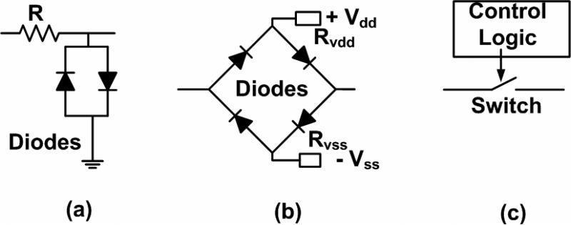
High frequency (HF) ultrasound (>15 MHz) imaging is widely used for many biomedical applications such as small animal or intravascular ultrasound imaging due to its superior resolution over conventional, lower frequency ultrasound [1]. The performance of ultrasound systems depends on the transducer and electronics including the expanders and limiters [2]. The limiters are used to protect the ultrasound receiver from the HV signals produced by the transmitter. As the frequency of the transducer increases, the performance of the receiver, including the limiter degrades [2]. This is because the parasitic impedance of the devices becomes more significant at high frequencies [3]. Therefore, the limiter design needs to be improved for HF ultrasound systems. For ultrasonic transducers and systems, several limiter topologies have been developed. There are both passive- and active-type limiters. Passive-type limiters can include diode configurations while active-type limiters require biasing or control circuits like bridge-based or switch-based designs. The limiter structures are shown in Fig.1.
Fig. 1.
Block diagram of the limiter architectures for (a) the diode, (b) bridge-based and (c) switch-based limiters.
Passive-type limiters typically have a resistor with two single diodes [4]. In the diode limiter (Fig. 1 a), the diodes are supposed to work as an open switch for low voltage and as a short switch for HV operations. Therefore, the diode limiter protects the receiver because the discharged HV signals goes into the ground through the diodes and the low voltage echo signals can pass through the resistor into the receiver. The diode limiter has been widely used in ultrasound systems because they are easy to integrate into the ultrasound electronics. However, the limiter attenuates the signal and causes ring-down at higher frequencies [4]. To eliminate the undesired characteristic, active-type limiters have been proposed. In the bridge-based limiter (Fig. 1 b), the diodes are forward biased in low voltage so the echo signals are transmitted into the receiver. In the HV operation, the diodes are reverse biased so these HV signals are isolated from the receiver [5]. The bridge-based limiter enables wideband operation but requires biasing circuits and a reliable DC power supply due to poor noise rejection [4]. In the switch-based limiter (Fig. 1 c), the switch is closed for the low voltage and it is open when the HV signals goes into the receiver. The switch-based limiter may reduce ring-down since the switch can block the ring down. However, this design still causes the signal attenuation due to the transistor equivalent resistances and requires the use of control logic [4]. These significant drawbacks make it an unattractive solution for a multi-channel ultrasound system [6].
For HF ultrasound system, there are desirable limiter characteristics. In a typical pulse-echo measurement, the HV pulses are sent through the limiter and it may mask lower echo signals. Therefore, in order not to interfere with the echo signals, a limiter with less distortion is desired. At high frequencies, if the distance between the transducer and target is short, the transmitted pulses may interfere with the echo signals. Therefore, the limiter needs a quick response time. To implement multi-channel ultrasound system, it is desirable to minimize the number of the connection of the protection circuits so the limiters without control logic may be preferable [6].
2. The limiter architectures
In this paper, we propose new passive-type limiter utilizing BPTs in order to improve the THD and RT for ultrasound imaging systems. For ultrasound applications, limiters should have high breakdown voltages and low impedances. The BPT devices are NPN and PNP BPTs that can provide lower impedances and higher breakdown voltages than low-voltage transistors. The working mechanisms of the diode-based and BPT-based limiters are both similar; for positive HV signals, the unwanted current goes through NPN BPTs to ground. For negative HV signal, the current goes through PNP BPTs to ground. A similar scheme has been used to protect the chip from the electrostatic discharge phenomenon [7]. Fig. 2 shows the limiter architectures.
Fig. 2.
The architectures of the diode, commercial and BPT-based limiters.
The diode limiter consists of one power resistor (Rin), two single diodes (1N4148, NXP Semiconductors, Eindhoven) and transmission lines. These diodes have a high breakdown voltage (100 V). The transmission lines were used to discharge pulse rapidly into the ground [8]. The commercial limiter (DL-1, Matec Instruments, Northborough, MA) has two resistors and several diodes. The BPT-based limiter has one power resistor, NPN and PNP BPT (ZTX 453 and 553, Diodes Inc., Dallas, Texas) and transmission lines.
3. The small and large signal models of the BPT-based limiter scheme
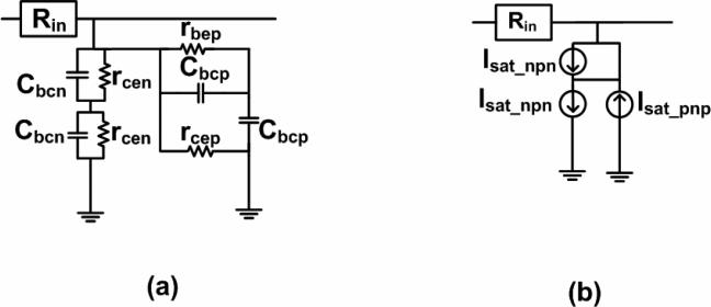
The returned echo signals as well as discharged HV signals pass through the limiter. Therefore, the small and large signal models need to be used in order to predict the limiter behavior. As the frequency increases, the parasitic impedance of the BPTs deteriorates their performances. Therefore, a high frequency small signal (HFSS) model is used to implement the HFSS model for BPT-based limiter (Fig. 3 a) to estimate limiter bandwidth [3]. The bandwidth is limited by the two different kinds of collector-emitter resistances (rcen and rcep) and base-collector capacitances (Cbcn and Cbcp) with the input resistance (Rin). We used the large signal (LS) model of the BPT-based limiter (Fig. 3 b) to approximate the THD of the limiter [3]. The BPT-based limiter was designed to minimize voltage drop by inserting one extra NPN BPT into the set of the NPN and PNP BPTs because of the different saturation currents of the NPN and PNP BPTs (Isat_npn and Isat_pnp). Since the diode and BPT may produce harmonic signals, we calculated the THD to evaluate their nonlinear performances.
Fig. 3.
The (a) HFSS model and (b) LS model for BPT-based limiter.
4. Limiter evaluation methods, results and discussion
At high frequencies, the transducer attenuation caused by the receiver is increased. To minimize attenuation, the cable length should be a quarter wavelength [9]. Therefore, the length should be kept at 52.5 cm for 100MHz transducer. Methods which were used to evaluate the limiter performances are described. Both the low voltage echo signals and discharged HV pulses pass through the limiters so different signal amplitude were evaluated during testing. Since the diode forward voltage is about 1 Vp-p and BPT threshold voltage is about 0.5 Vp-p, the low and high voltage signals should be selected to be less than 0.5 Vp-p and higher than 1 Vp-p, respectively. The BPT-based limiter was evaluated and compared against the diode and commercial limiters to determine which the optimal design was.
4.1. IL, THD and TNF
The IL was obtained by dividing the output signal of the limiter by its original magnitude without a limiter. To calculate the THDs, the 1st–5th harmonics were chosen because of the 1 GHz sampling rate of the oscilloscope (LC534, LeCroy, Chestnut Ridge, NY). Since the noise of the limiter may affect the total noise performances of the limiter followed by the preamplifier [10], the total noise figure (TNF) was measured by a spectrum analyzer (EE4401B, Agilent Technologies, Santa Clara, CA).
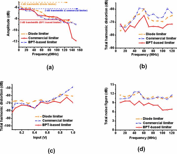
In Fig. 4 a, using 50 mVp-p 100 MHz signals, the BPT-based limiter had a lower IL (–7.7 dB) than those of the diode and commercial limiters (–8.0 dB). However, above 130 MHz, the IL of the BPT-based limiter abruptly decreased because of the limited BPT bandwidth (135 MHz). Fig. 4 b shows how the THD of BPT-based limiter changes over the frequency range. The BPT-based limiter had lower THD (–74.6 dB) than did the commercial limiter (–66.3 dB) at 100 MHz. Fig 4 c shows the THD of the limiters vs the test signals. As the input voltage increased, the THD of the BPT-based limiter was generally lower than that of the commercial limiter. Fig. 4 d shows the TNF of the limiters and the preamplifiers. The TNF was affected by the NF of the limiter and the impedance of the preamplifier because the NF of the preamplifier was about 1 dB up to 200 MHz [11]. In Fig. 4 d, the TNF with the BPT-based limiter (6.6 dB) was found to be lower than those of the diode and commercial limiter (10.4 and 10.7 dB) at 100 MHz.
Fig. 4.
(a) The IL and (b) THD of limiters using 50 mVp-p input signals and (c) THD of the limiters vs. test signals, and (d) TNFs of limiters and a preamplifier.
Table 1 shows the simulated and measured IL, THD and TNF of the limiters. The IL and THD simulated data were obtained using PSpice software (Cadence Design Systems, San Jose, CA) and are included in Table 1 for reference. However, the simulated TNF, RT, electrical impedance and pulse-echo test data was not shown because there are no available PSpice libraries for commercial preamplifier, expander, limiter and monocycle generator.
Table 1.
The IL, THD and TNF of the limiters at 100 MHz.
| IL (dB) | THD (dB) | TNF (dB) | |||
|---|---|---|---|---|---|
| Simulated | Measured | Simulated | Measured | Measured | |
| Diode limiter | –8.3 | –8.0 | –73.3 | –69.5 | 10.4 |
| Commercial limiter | ------- | –8.0 | ------- | –66.3 | 10.7 |
| BPT-based limiter | –7.5 | –7.7 | –76.3 | –74.6 | 6.6 |
4.2. RT, electrical impedance and pulse-echo responses
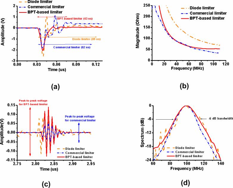
The limiter should protect the preamplifier from the discharged pulses and should recover quickly from the pulses in order to reduce the interference with echo signals. To evaluate the transient response of the limiter, its RT was measured. The RT was the elapsed time from when the suppressed output signal first responded to the input signal until the output fell within +/– 1% of the final output. A pulse from the function generator was used to drive an amplifier (325LA, E&I, Rochester, NY). Next, a 100 MHz 50 Vp-p negative pulse from the amplifier was sent through the limiter and attenuator. In Fig. 5 a, the results indicate that the BPT-based limiter has a faster RT (43 ns) than the diode and commercial limiters (89 and 82 ns).
Fig. 5.
(a) The output suppressed signals of the limiters, (b) magnitudes of the limiter impedances, (c) the sensitivity and (d) spectrum of the echo responses with limiters and preamplifier for a 100MHz LiNbO3 transducer.
The electrical impedances of the limiters were measured with an impedance analyzer (HP4294A, Agilent Technologies, Santa Clara, CA) because impedance matching is more crucial for HF ultrasound systems [2]. The preamplifier was added after the limiter and the 50 Ω load was also connected following the preamplifier because the weak echo signal from the transducer is supposed to pass through the limiter and preamplifier. In Fig. 5 b, the magnitude value (52.7 Ω) of BPT-based limiter is closer to 50 Ω rather than those of the diode and commercial limiters (73.8 and 36.1 Ω) at 100 MHz. Therefore, for BPT-based limiter, the input impedance mismatch for the preamplifiers is smaller.
The pulse-echo responses of the transducers were measured to estimate the limiter capability. Each limiter was connected with a 100 MHz LiNbO3 transducer (1.3 mm aperture size and 2 mm focus) fabricated by our group. The transducer was positioned in a de-ionized water bath opposite a quartz reflector about 2 mm distance. A pulser (AVB2-TE-C, Avtech Electorsystems, Ottawa) was used to excite the transducer with a expander (DEX-3, Matec Instrument, Northborough, MA). The echoes from the transducer were sent through the limiters and 36 dB gain preamplifier (AU-1114). In Fig. 5 c and d, the results showed that using BPT-based limiter, the measured −6 dB bandwidth and peak-to-peak voltage of the transducer were improved by 22 % and 140 % compared with that of the transducer using the commercial limiter. This improvement is possible because the magnitude of the BPT-based limiter (52.7 Ω) is closer to 50 Ω than that of the commercial limiter (36.1 Ω) at 100 MHz. Furthermore, the bandwidth of the BPT-based limiter was still wide enough to cover up to 135 MHz; consequently using BPT-based limiter for the transducers did not appear to compromise its performance.
5. Conclusion
In traditional ultrasound imaging systems, the bridge-based limiter has been used to reduce ring down. Therefore, the BPT-based limiter may replace the diode-bridge components because of its quicker RT and lower ring down without the need for any additional control logic and DC power supply. However, the price of the BPTs is much higher than the diodes. Therefore, chip fabrication processes may be utilized to build the limiter economically. With the chip process, the undesired effects caused by the unmatched BPT impedances would be further reduced since the unbalanced amplitudes of the parasitic impedances of the BPT affect the performances. Lastly, the BPT specifications such as the size and parasitic impedances need to be optimized and the limiter performances should be simulated.
The measured performances of the limiters were summarized in Table 2. Among the limiters, BPT-based limiter exhibited the best performance at 100 MHz because of its lowest IL (–7.7 dB), THD (–74.6 dB) and TNF (6.6 dB) and fastest RT (43 ns) at the price of the limited bandwidth (135 MHz). The measured bandwidth and sensitivity of a high frequency transducer with BPT-based limiter were found to be improved compared with the commercial limiter. These results demonstrate that this BPT-based limiter may be a good choice for high-frequency ultrasound systems.
TABLE 2.
The summary of the limiters’ performances.
| Performances | Diode limiter | Commercial limiter | BPT-based limiter | |
|---|---|---|---|---|
| IL (dB) | 20 MHz | –6.0 | –6.6 | –6.3 |
| 60 MHz | –6.8 | –7.7 | –7.4 | |
| 100 MHz | –8.0 | –8.0 | –7.7 | |
| THD (dB) | 20 MHz | –72.4 | –74.1 | –77.3 |
| 60 MHz | –59.9 | –59.9 | –64.9 | |
| 100 MHz | –69.5 | –66.3 | –74.6 | |
| TNF (dB) | 20 MHz | 11 | 10.4 | 9.6 |
| 60 MHz | 10.7 | 10.3 | 8.2 | |
| 100 MHz | 10.4 | 10.7 | 6.6 | |
| Bandwidth (MHz) | 131 | 147 | 135 | |
| RT (ns) | 89 | 82 | 43 | |
* The IL, THD, and TNF values were measured at 50 mVp-p. RT is the time caused by negative pulse.
Highlights.
A bipolar-power-transistor-(BPT)-based limiter is presented.
BPT-based limiter exhibit relatively good performances at high frequency operation.
The BPT-based limiter is good choice for high frequency ultrasound systems.
Acknowledgment
The authors thank Mr. Thomas Cummins and for his editing contribution. This research was supported by National Institutes of Health Grant # P41-EB002182.
Footnotes
Publisher's Disclaimer: This is a PDF file of an unedited manuscript that has been accepted for publication. As a service to our customers we are providing this early version of the manuscript. The manuscript will undergo copyediting, typesetting, and review of the resulting proof before it is published in its final citable form. Please note that during the production process errors may be discovered which could affect the content, and all legal disclaimers that apply to the journal pertain.
References
- 1.Shung KK. Diagnostic Ultrasound: Imaging and Blood Flow Measurements. Taylor & Francis Group; 2005. [Google Scholar]
- 2.Choi H, Li X, Lau S-T, Hu C, Zhou Q, Shung KK. Development of integrated preamplifier for high-frequency ultrasonic transducers and low-power handheld receiver. IEEE Trans. Ultrason. Ferroelectr. Freq. Control. 2011;58:2646–2658. doi: 10.1109/TUFFC.2011.2127. [DOI] [PMC free article] [PubMed] [Google Scholar]
- 3.Lee TH. The Design of CMOS Radio-Frequency Integrated Circuits. University Press; Cambridge: 2004. [Google Scholar]
- 4.Fuller MI, Blalock TN, Hossack JA, Walker WF. Novel transmit protection scheme for ultrasound systems. IEEE Trans. Ultrason., Ferroelect., Freq. Contr. 2007;54:79–86. doi: 10.1109/tuffc.2007.213. [DOI] [PubMed] [Google Scholar]
- 5.Vogt M, Paul B, Scharenberg S, Scharenberg R, Ermert H. Development of a high frequency ultrasound skin imaging system: optimization utilizing time domain reflectometry and network analysis in. IEEE Ultrason Symp. 2003:744–747. [Google Scholar]
- 6.Hu CH, Snook KA, Cao PJ, Shung KK. High-frequency ultrasound annular array imaging. Part II: digital beamformer design and imaging. IEEE Trans. Ultrason., Ferroelect., Freq. Contr. 2006;53:309–316. doi: 10.1109/tuffc.2006.1593369. [DOI] [PubMed] [Google Scholar]
- 7.Voldman SH, Gerosa G, Gross VP, Dickson N, Furkay S, Slinkman J. Analysis of snubber-clamped diode-string mixed voltage interface ESD protection network for advanced microprocessors. Proc. IEEE EOS/ESD Symp. 1995:43–61. [Google Scholar]
- 8.Gundersen M, Kuthi A, Behrend M, Vernier T. Bipolar Nanosecond Pulse generation using transmission lines for cell electromanipulation. Proc. IEEE Power Modulator Symp. 2004:224–227. [Google Scholar]
- 9.Cannata JM, Williams JA, Qifa Z, Ritter TA, Shung KK. Development of a 35-MHz piezo-composite ultrasound array for medical imaging. IEEE Trans. Ultrason., Ferroelect., Freq. Contr. 2006;53:224–236. doi: 10.1109/tuffc.2006.1588408. [DOI] [PubMed] [Google Scholar]
- 10.Friis HT. Noise Figures of Radio Receivers. Proceedings of the IRE. 1944;32:419–422. [Google Scholar]
- 11.AU-1114 datasheet, MITEQ. 2010 [Online]. Available: www.miteq.com/products/viewmodel.php?model=AU-1114.


