With global demand rising faster than availability, fresh water is quickly becoming a limited resource. In fact, the United Nations estimates one-third of the world's population is living in water stressed regions, and by 2025 this number is expected to double.[1] Seawater desalination is an attractive solution to this problem, because seawater accounts for more than 97% of the world's water supply.[2] Currently, the primary limitation preventing the widespread use of seawater desalination as a fresh water supply is the immense amount of energy required to drive the process.[3] Here, we describe a new, electrochemically-mediated desalination (EMD) method for membraneless seawater desalination.
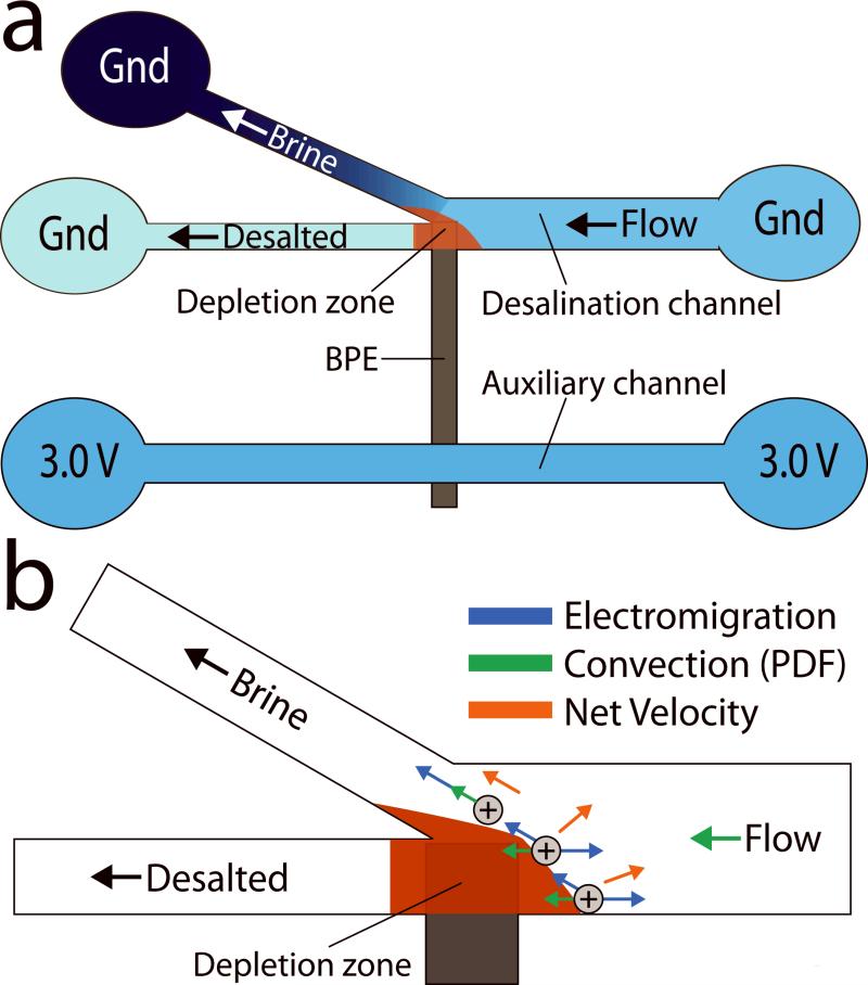
Our approach for desalination is illustrated in Scheme 1a. A seawater feed is separated into brine and desalted water streams at the junction of a branched microchannel where a bipolar electrode (BPE)[4] is present. The anodic pole of the BPE generates an ion depletion zone,[5] and hence a local electric field gradient that redirects ions present in seawater to the brine channel. Importantly, this device operates with an energy efficiency of 25 mWh/L (25±5% salt rejection, 50% recovery), which is near the theoretical minimum amount of energy required for this process (~17 mWh/L).[6] In addition to this energy efficiency, the approach provides three other important benefits relative to currently available desalination methods. First, EMD does not require a membrane, thereby eliminating a major drawback of reverse osmosis (RO), currently the most widespread method for desalination.[7] Second, EMD requires only a simple 3.0 V power supply to operate and therefore, in the future, may be employed in resource-limited settings using a battery or low-power, renewable energy source. Third, the EMD platform may be prepared with little capital investment and could be implemented in a massively parallel format.[8]
Scheme 1.
Our group has developed microfluidic technologies using BPEs for the enrichment,[9] separation,[10] depletion,[11] and controlled delivery[12] of charged analytes. In all cases, the approach relies on the formation of a locally generated electric field gradient and control over convection. The basic operating principles of BPEs[13] and how they are able to generate electric field gradients have been previously described.[14] Briefly, if a sufficiently high potential bias (Etot) is applied across a microfluidic channel in which a BPE is present, faradaic reactions will occur at the BPE poles. In seawater, these faradaic reactions result in the formation of an ion depletion zone (region of high solution resistivity), thus producing a local electric field gradient and providing a means for controlling the movement of ions.[15]
Several other techniques, including dynamic field gradient focusing[16] and electric field gradient focusing,[17] also rely on a gradient in the electric field to control the transport of charged analytes. Most relevant to this work is a phenomenon called ion concentration polarization (ICP),[18] which generates an ion depletion zone when a potential bias applied across two fluidic channels causes a large proportion of ionic current to be carried by either anions or cations through a perm-selective material or a nanochannel exhibiting overlap of the electrical double layer. In fact, Han and coworkers have recently shown that ICP can be adapted to seawater desalination with a reported energy efficiency of 3750 mWh/L (~99% salt rejection, 50% recovery) for a small-scale system.[19] A number of other electrochemical approaches, including capacitive deionization,[20] a desalination battery,[21] and electrodialysis,[22] have also been implemented for seawater desalination, although these techniques are more commonly used to desalinate brackish water because their power consumption scales with the extent of salt removal.[23]
The EMD experiments reported here were carried out using a PDMS/quartz hybrid microfluidic device (22 μm-tall channels with a 100 μm-wide inlet and two 50 μm-wide outlets) outfitted with a pyrolyzed photoresist carbon (PPC)[24] BPE. Additional details regarding the device design, fabrication, and characterization can be found in the supporting information (SI). Both channels were filled with seawater collected near Port Aransas, Texas, USA. To prevent obstruction of the microfluidic channel, sand and debris present in the seawater sample were removed via sedimentation before use. Importantly, no other pre-treatment was required. This is in contrast to membrane-based desalination where further pre-treatment, such as disinfection and the addition of anti-scaling chemicals, is required to prevent fouling and maintain the structural integrity of the membrane.[25]
The experimental arrangement is shown in Scheme 1a. In the desalination channel, seawater is spiked with a fluorescent cationic tracer, tris (2,2'-bipyridyl) ruthenium (II) chloride ([Ru(bpy)3]2+),representative of ionic motion. A total pressure driven flow (PDF) of ~0.08 μL/min is initiated between the inlet and outlets by creating a solution height differential between them. Next, using Pt driving electrodes dipped into each of the five reservoirs, Etot = 3.0 V is applied. This creates a sufficiently large potential difference between the BPE poles to drive chloride oxidation and water reduction at the BPE anode and cathode, eqs 1 and 2, respectively. Importantly, chloride oxidation results in the neutralization of Cland hence an ion depletion zone and local electric field gradient near the BPE anode.
| (1) |
| (2) |
| (3) |
Although chloride oxidation is known to be the dominant anodic process occurring in seawater,[26] water oxidation also occurs by eq 3. Electrogenerated H+ arising from water oxidation may neutralize anions present in seawater, such as bicarbonate and borate, thus further contributing to ion depletion and the electric field gradient.
The electrophoretic velocity (uep) of an ion is governed by eq 4, where μep is its electrophoretic mobility and Vl is the local electric field strength.
| (4) |
In all regions of the desalination channel depicted in Scheme 1b, except near the ion depletion zone, ionic transport is dominated by PDF, which results in a net movement toward the outlets. However, as ions approach the local electric field gradient, they experience an increasing uep. At some point on this gradient, uep will exceed the convective velocity, and therefore cations will be directed toward the grounded reservoir in the brine stream. To maintain electroneutrality within the microchannel, anions are also redirected into the brine stream.
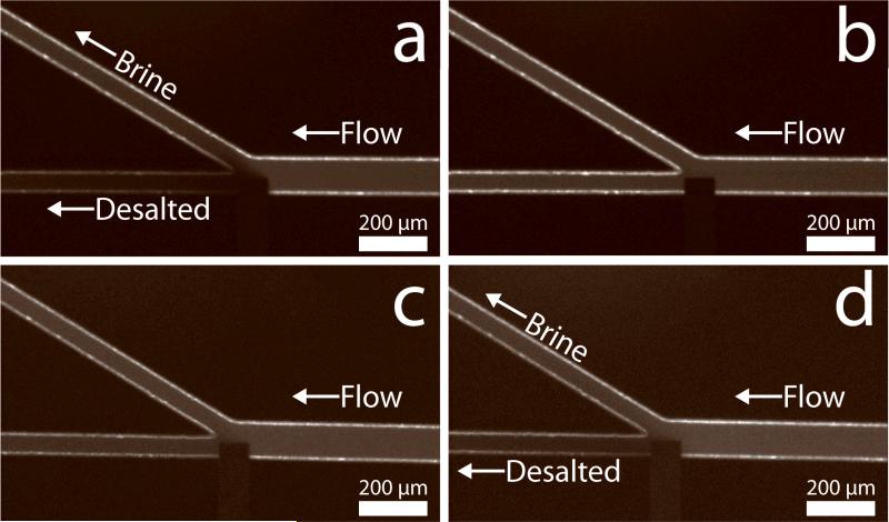
Figure 1 provides fluorescence micrographs confirming the electrochemically driven redirection of ions. In Figure 1a, the [Ru(bpy)3]2+ tracer, which represents the ions in seawater, is selectively directed into the brine stream. Conversely, water flowing into the lower channel is depleted of tracer. During this desalination process, in-situ conductivity measurements were performed using a procedure described in the SI. The average conductivity in the desalted stream from five individual trials was 37.5±2.5 mS/cm, indicating a ~25±5% salt rejection from the feed seawater (50 mS/cm). The power source was then turned off (Figure 1b, Etot = 0.0 V), whereupon the fluorescent tracer flowed into the desalted stream and the conductivity returned to 50 mS/cm. Although the salt rejection is lower than mature desalination technologies, the EMD process is far from optimized.
Figure 1.
Fluorescence micrographs showing the location of [Ru(bpy)3]2+ tracer, which is representative of the ions present in seawater. (a) The tracer in seawater is redirected into the brine stream with Etot = 3.0 V. (b) Same as (a) except Etot = 0.0 V. In this case, the tracer flows into both outlets. (c) In 50 mS/cm Na2SO4, the tracer flows into both outlets with Etot = 3.0 V. (d) In 50 mS/cm NaCl, the tracer is redirected into the brine stream with Etot = 3.0 V. In all cases, the total PDF was ~0.08 μL/min.
The experiment represented in Figure 1c was carried out exactly like that described for Figure 1a, but using 50 mS/cm Na2SO4 instead of seawater. The purpose of this experiment is to demonstrate that the formation of a local electric field gradient is essential for driving desalination. The Na2SO4 eliminates the possibility of an ion depletion zone forming due to eq 1 or by the neutralization of weak bases present in seawater with electrogenerated H+. In this case, there is no selective redirection of [Ru(bpy)3]2+, which emphasizes the importance of Cl- for desalting.The slight decrease in fluorescence intensity in the desalted stream occurs as a result of O2, generated by water oxidation, quenching the [Ru(bpy)3]2+ fluorescence.[27] Importantly, electric field measurements presented in the SI demonstrate that no local electric field gradient is observed in the presence of Na2SO4. Experiments were also carried out exactly like that described for Figure 1a, except with 50 mS/cm NaCl. In this case (Figure 1d), [Ru(bpy)3]2+ is redirected into the brine stream, clearly implicating Cl- as a critical factor in the desalination process. Electric field measurements (SI) confirm the formation of a local electric field gradient in the presence of NaCl. The key point is that the formation of a local electric field gradient is necessary to induce EMD.
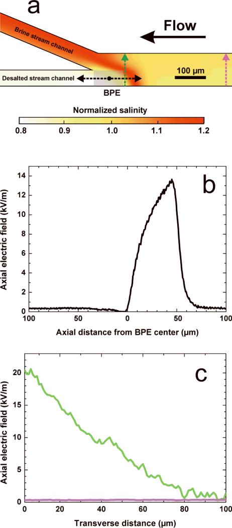
Numerical simulations were used to confirm our proposed mechanism for desalination. The simulations mirror the experiment corresponding to Figure 1d: desalination of a 50 mS/cm NaCl solution with the assumption of Cl– oxidation at the BPE anode. Details regarding the theoretical background and numerical methods can be found in the SI. Figure 2a shows the simulated distribution of salinity in the region of interest close to the BPE anode, normalized by its value in the desalination channel inlet. The developed electric field gradient, illustrated by Figures 2b and 2c, redirects ions toward the brine stream, resulting in a 20% reduction of salinity in the desalted stream. This result is in excellent agreement with the experimental findings (~25±5% salt rejection).
Figure 2.
(a) Local salinity distribution simulated for a 50 mS/cm NaCl solution with Etot = 3.0 V and a total PDF rate of 0.08 μL/min from inlet to outlets; the current through the BPE is 50 nA. (b) Simulated profile of the axial electric field strength along the centerline of the desalted stream (as indicated by the black arrows in panel a). (c) Simulated profiles of the axial electric field strength along the transverse direction of the desalination channel (as indicated by the green and purple arrows in the corresponding color in panel a).
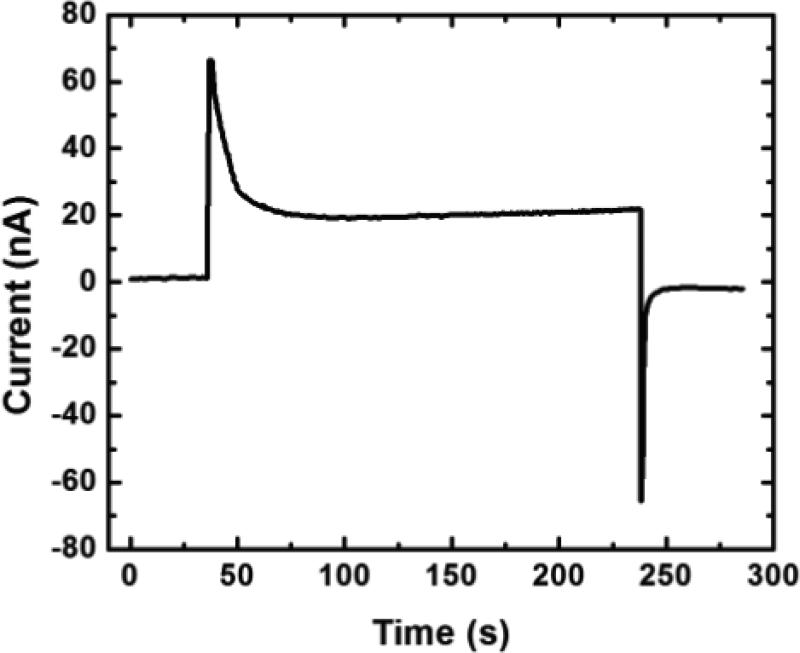
Figure 3 shows a representative plot of total current through the device vs. time. The steady-state operating current was 20 nA (device-to-device variation was 10-80 nA) with Etot = 3.0 V driving the desalination process, hence yielding a power consumption of 60 nW. The average flow rate of desalted water was ~0.04 μL/min, resulting in an energy efficiency of just 25 mWh/L for 25±5% salt rejection at a 50% recovery. Thus, this device compares competitively with efficient, state-of-the-art seawater desalination technologies, such as RO, which typically operate at ~2000 mWh/L (~99% salt rejection, 50% recovery) for a process that requires a theoretical minimum energy of ~1000 mWh/L.[28] Note that these RO efficiencies do not include the energy associated with seawater intake, pre-treatment required to maintain membrane performance, or post-treatment. Importantly, RO efficiency improves as the scale of the process is increased to incorporate energy recovery systems,[2a] and therefore the energy required to run small-scale RO desalination is higher than 2000 mWh/L. This suggests that EMD, powered by a 3.0 V battery pack (SI), could be competitive for small-scale applications and have utility in resource-limited settings.
Figure 3.
A plot of total current vs. time during a seawater desalination experiment showing the steady-state operating current of 20 nA required to drive desalination. Both microchannels were filled with seawater. Etot = 3.0 V was applied and the total PDF was ~0.08 μL/min.
The fundamental operating principles of EMD are different than those of membrane and thermal desalination technologies. For example, membrane-based desalination requires an applied pressure greater than the high osmotic pressure of seawater (~30 atm) to desalt. With regard to thermal desalination, sufficient energy must be provided to vaporize water. In both cases, there are clearly defined minimum energy requirements. EMD requires only enough energy to oxidize a sufficient percentage of the total Cl- present in seawater to generate the local electric field gradient. In the present configuration this amounts to ~0.01% (SI). EMD does require PDF, but the power required for this gravity driven flow is negligible (112 pW, SI).
In summary, we have demonstrated a membraneless and energy efficient technique for seawater desalination. EMD relies on the oxidation of Cl-, which generates an ion depletion zone and local electric field gradient to redirect sea salts into a brine stream. This result is important for a number of reasons. First, the technique is membraneless, and therefore does not suffer from membrane fouling or damage and does not require extensive pre-treatment prior to desalination. Second, EMD achieves energy efficiencies of 25 mWh/L for 25±5% salt rejection at a 50% recovery of desalted water (theoretical minimum energy efficiency is ~17 mWh/L). Lastly, the simple design, operation, and equipment required to perform EMD greatly reduces the capital costs associated with desalination. In the future, it may be possible to use arrays of channels and BPEs to increase the production of desalted water. Moreover, we believe there is considerable room for optimization of the channel and electrode designs.
Supplementary Material
Footnotes
We gratefully acknowledge the Chemical Sciences, Geosciences, and Biosciences Division, Office of Basic Energy Sciences, Office of Science, U.S. Department of Energy (contract no. DE-FG02-06ER15758) for supporting the basic research that led to the development of this technology. We acknowledge financial support from Okeanos Technologies, LLC, for supporting certain aspects of the technological implementation. The Robert A. Welch Foundation provides sustained support for our research (Grant F-0032). We also thank Prof. Don Paul (UT-Austin) for helpful discussions about desalination and Mr. Tim Hooper (UT-Austin) for providing technical assistance with the conductivity measurements. R.K.A. receives support from NIH training grant (NIH T32 CA138312). Finally, we thank the Deutsche Forschungsgemeinschaft (grant TA 268/5-1, DFG, Bonn, Germany) for support of the simulations described in this article.
Supporting information for this article is available on the WWW under http://www.angewandte.org or from the author.
Contributor Information
Kyle N. Knust, Department of Chemistry and the Center for Nano- and Molecular Science and Technology, The University of Texas at Austin, 105 E. 24th St., Stop A5300 Austin, Texas 78712-0165, U.S.A.
Dzmitry Hlushkou, Department of Chemistry, Philipps-Universität Marburg, Hans-Meerwein-Strasse, 35032 Marburg, Germany.
Robbyn K. Anand, Department of Chemistry and the Center for Nano- and Molecular Science and Technology, The University of Texas at Austin, 105 E. 24th St., Stop A5300 Austin, Texas 78712-0165, U.S.A.
Ulrich Tallarek, Department of Chemistry, Philipps-Universität Marburg, Hans-Meerwein-Strasse, 35032 Marburg, Germany tallarek@staff.uni-marburg.de.
Richard M. Crooks, Department of Chemistry and the Center for Nano- and Molecular Science and Technology, The University of Texas at Austin, 105 E. 24th St., Stop A5300 Austin, Texas 78712-0165, U.S.A..
References
- 1.United Nations World Water Development Report 2. 2006 [Google Scholar]
- 2.a Shannon MA, Bohn PW, Elimelech M, Georgiadis JG, Marinas BJ, Mayes AM. Nature. 2008;452:301–310. doi: 10.1038/nature06599. [DOI] [PubMed] [Google Scholar]; b Service RF. Science. 2006;313:1088–1090. doi: 10.1126/science.313.5790.1088. [DOI] [PubMed] [Google Scholar]
- 3.Hightower M, Pierce SA. Nature. 2008;452:285–286. doi: 10.1038/452285a. [DOI] [PubMed] [Google Scholar]
- 4.Fosdick SE, Knust KN, Scida K, Crooks RM. Angew. Chem. Int. Ed. 2013 doi: 10.1002/anie.201300947. DOI: 10.1002/anie.201300947. [DOI] [PubMed] [Google Scholar]
- 5.Anand RK, Sheridan E, Knust KN, Crooks RM. Anal. Chem. 2011;83:2351–2358. doi: 10.1021/ac103302j. [DOI] [PubMed] [Google Scholar]
- 6.a Cengel YA, Cerci Y, Wood B. Proceedings of the ASME Advanced Energy Systems Division. 1999;39:537–543. [Google Scholar]; b Cerci Y, Cengel YA, Wood B. Proceedings of the ASME Advanced Energy Systems Division. 1999;39:545–552. [Google Scholar]
- 7.Penate B, Garcia-Rodriguez L. Desalination. 2012;284:1–8. [Google Scholar]
- 8.Bard AJ. Integrated chemical systems: a chemical approach to nanotechnology. John Wiley & Sons, Inc.; New York, NY: 1994. [Google Scholar]
- 9.Dhopeshwarkar R, Hlushkou D, Nguyen M, Tallarek U, Crooks RM. J. Am. Chem. Soc. 2008;130:10480–10481. doi: 10.1021/ja8036405. [DOI] [PubMed] [Google Scholar]
- 10.Laws DR, Hlushkou D, Perdue RK, Tallarek U, Crooks RM. Anal. Chem. 2009;81:8923–8929. doi: 10.1021/ac901545y. [DOI] [PubMed] [Google Scholar]
- 11.Sheridan E, Knust KN, Crooks RM. Analyst. 2011;136:4134–4137. doi: 10.1039/c1an15510e. [DOI] [PubMed] [Google Scholar]
- 12.Scida K, Sheridan E, Crooks RM. Lab Chip. 2013 doi: 10.1039/c3lc50321f. Submitted. [DOI] [PubMed] [Google Scholar]
- 13.Mavré F, Anand RK, Laws DR, Chow K-F, Chang B-Y, Crooks JA, Crooks RM. Anal. Chem. 2010;82:8766–8774. doi: 10.1021/ac101262v. [DOI] [PubMed] [Google Scholar]
- 14.a Hlushkou D, Perdue RK, Dhopeshwarkar R, Crooks RM, Tallarek U. Lab Chip. 2009;9:1903–1913. doi: 10.1039/b822404h. [DOI] [PubMed] [Google Scholar]; b Perdue RK, Laws DR, Hlushkou D, Tallarek U, Crooks RM. Anal. Chem. 2009;81:10149–10155. doi: 10.1021/ac901913r. [DOI] [PubMed] [Google Scholar]; c Anand RK, Sheridan E, Hlushkou D, Tallarek U, Crooks RM. Lab Chip. 2011;11:518–527. doi: 10.1039/c0lc00351d. [DOI] [PubMed] [Google Scholar]
- 15.Knust KN, Sheridan E, Anand RK, Crooks RM. Lab Chip. 2012;12:4107–4114. doi: 10.1039/c2lc40660h. [DOI] [PubMed] [Google Scholar]
- 16.Huang Z, Ivory CF. Anal. Chem. 1999;71:1628–1632. [Google Scholar]
- 17.Humble PH, Kelly RT, Woolley AT, Tolley HD, Lee ML. Anal. Chem. 2004;76:5641–5648. doi: 10.1021/ac040055+. [DOI] [PubMed] [Google Scholar]
- 18.Kim SJ, Song Y-A, Han J. Chem. Soc. Rev. 2010;39:912–922. doi: 10.1039/b822556g. [DOI] [PMC free article] [PubMed] [Google Scholar]
- 19.Kim SJ, Ko SH, Kang KH, Han J. Nat. Nanotechnol. 2010;5:297–301. doi: 10.1038/nnano.2010.34. [DOI] [PubMed] [Google Scholar]
- 20.Suss ME, Baumann TF, Bourcier WL, Spadaccini CM, Rose KA, Santiago JG, Stadermann M. Energy Environ. Sci. 2012;5:9511–9519. [Google Scholar]
- 21.Pasta M, Wessells CD, Cui Y, La Mantia F. Nano Lett. 2012;12:839–843. doi: 10.1021/nl203889e. [DOI] [PubMed] [Google Scholar]
- 22.Sadrzadeh M, Mohammadi T. Desalination. 2008;221:440–447. [Google Scholar]
- 23.Oren Y. Desalination. 2008;228:10–29. [Google Scholar]
- 24.Ranganathan S, McCreery R, Majji SM, Madou M. J. Electrochem. Soc. 2000;147:277–282. [Google Scholar]
- 25.Geise GM, Lee H-S, Miller DJ, Freeman BD, McGrath JE, Paul DR, Polym J. Sci., Part B Polym. Phys. 2010;48:1685–1718. [Google Scholar]
- 26.Bennett JE. Int. J. Hydrogen Energy. 1980;5:401–408. [Google Scholar]
- 27.Carraway ER, Demas JN, DeGraff BA, Bacon JR. Anal. Chem. 1991;63:337–342. [Google Scholar]
- 28.Elimelech M, Phillip WA. Science. 2011;333:712–717. doi: 10.1126/science.1200488. [DOI] [PubMed] [Google Scholar]
Associated Data
This section collects any data citations, data availability statements, or supplementary materials included in this article.


