Abstract
In vivo fluorescent cellular imaging of deep internal organs is highly challenging, because the excitation needs to penetrate through strong scattering tissue and the emission signal is degraded significantly by photon diffusion induced by tissue-scattering. We report that by combining two-photon Bessel light-sheet microscopy with nonlinear structured illumination microscopy (SIM), live samples up to 600 microns wide can be imaged by light-sheet microscopy with 500 microns penetration depth, and diffused background in deep tissue light-sheet imaging can be reduced to obtain clear images at cellular resolution in depth beyond 200 microns. We demonstrate in vivo two-color imaging of pronephric glomeruli and vasculature of zebrafish kidney, whose cellular structures located at the center of the fish body are revealed in high clarity by two-color two-photon Bessel light-sheet SIM.
OCIS codes: (170.2520) Fluorescence microscopy, (170.6900) Three-dimensional microscopy
Introduction
In vivo cellular imaging of organs in live animals is highly challenging because it requires a technique that penetrates thick surrounding tissue layers while still maintaining cellular resolution. Light-sheet or selected plane illumination microscopy [1, 2] allows selective illumination of tissue layers and fast cellular 3D imaging of live organisms compared to conventional confocal or multi-photon imaging. However, the field-of-view of light-sheet microscopy is limited by the depth of focus of the sheet and the penetration depth of the illumination through the tissue. Two-side sheet illumination can double the field-of-view by illuminating the sample from opposite sides, but adds complexity and cost to the imaging system [3, 4]. Two-photon light-sheet microscopy can extend the penetration of illumination by using longer wavelength of light, but is still limited by the depth-of-focus and requires two-side illumination to reach a 250-μm-wide field-of-view [5]. Furthermore, images from light-sheet microscopy are affected by tissue scattering of emitted fluorescence photons, which degrades the lateral image resolution in deep layers. As the result, light-sheet images often are strongly blurred in areas where tissue layer above the sheet is thick. Multi-view imaging capture [3, 5], can improve imaging performance and achieve cellular resolution images in the 100-μm-thick tissue layer near the surface of a sample, but offers little help on resolving deep structures at the center.
The above limitations make light-sheet imaging of large or deep organs in live animals a challenging task, because: first, it is difficult to effectively illuminate deep structures; second, the emission image contrast and resolution are degraded by photon diffusion; finally, a limited field-of-view may not be enough for imaging large organs.
In this paper we address these limitations by combining two-photon Bessel light-sheet imaging with nonlinear structured illumination microscopy. The approach enhances the imaging performance in both the excitation and the emission paths:
(1) In the excitation path, two-photon excitation increases the excitation penetration compared to one-photon excitation [5], and the Bessel light-sheet has better penetration in scattering tissue compared to Gaussian beam [6]. The Bessel beam has an extended focal depth which also supports a larger light-sheet, making it possible to image a larger field-of-view than Gaussian two-photon light-sheet while maintaining high axial resolution [7].
Two-photon Bessel light-sheet imaging had been previously demonstrated in stained tissue samples [7]. Its effectiveness is not yet tested in vivo. Our system achieves an extended field-of-view of 600 μm, twice of the previously reported two-photon Bessel light-sheet system [7] and the two-side illuminated two-photon Gaussian light-sheet system [5]. At a lateral resolution of 0.5 μm and an axis resolution of 2 μm, the wide field-of-view system can image 3D structures of the entire vasculature in the larvae head of a live transgenic zebrafish, proving that the Bessel beam can effectively illuminate 600 μm into animal tissue with single-side illumination. In zebrafish, the system is able to image more than 500 μm deep from the top surface of the fish, demonstrating an imaging depth deeper than any previously reported light-sheet microscopes.
The photo-toxicity of Bessel light-sheet could potentially be higher than Gaussian light-sheet, because the light is tightly focused over a longer distance. Our results show that, similar to two-photon Gaussian light-sheet, two-photon Bessel light-sheet does not cause trauma or long-term photo-toxicity in live embryos and larvae.
(2) In the emission path, incoherent nonlinear structured-illumination microscopy (SIM) is used to reject diffused photons due to tissue scattering. Previously a three-phase optical sectioning method [8] had been used in light-sheet microscopy to reject diffused photons and improve image quality in deeper layers [9]. It had been proven that nonlinear SIM [10] has superior signal-to-noise ratio than the three-phase optical sectioning method in removing out-of-focal-plane photons due to side-bands of one-photon Bessel light-sheet imaging [11]. As tissue scattering and out-of-focal-plane photons both impose diffused background over the ballistic image, nonlinear SIM should provide more effective diffusion-rejection than the three-phase optical sectioning method in deep tissue light-sheet imaging.
However, we found that the standard nonlinear SIM image reconstruction algorithm, which can effectively remove weak out-of-focus photons, fails to completely remove strong diffused photon background. Residual diffused photons, in either confocal line-detection [7] or the standard nonlinear SIM algorithm, will introduce artifacts in reconstructed images. A critical modification of the nonlinear SIM algorithm is necessary to improve the diffusion reduction and remove diffusion-induced artifacts.
We demonstrate diffusion-reduced two-color in vivo imaging of pronephric glomeruli in live double transgenic zebrafish larva. The zebrafish kidney locates at the center of the larva and is beyond 200 μm in depth from all sides of the surface. Because it does not reach full developmental stage until the larva becomes pigmented and opaque, images of pronephric glomeruli are severely blurred by tissue scattering when a uniform light-sheet illumination is used. With the improved SIM method and two-photon Bessel light-sheet microscopy, 3D organization of two cell types in the kidney is revealed with high clarity.
Two-photon Bessel light-sheet microscope
Optical setup
Figure 1(a) shows the schematic of the Bessel light-sheet two-photon microscope. Output from a femtosecond Ti:Sapphire laser (Newport Tsunami) is first expanded to a FWHM of 8 mm, so that the full aperture of the phase spatial light modulator (SLM) (Hamamatsu X10468-07, 800-by-600, 20 μm pitch) is used and the pixilation effect from the SLM is minimal. First order reflection from the SLM is delivered to an objective lens (Mitutoyo 20x long working distance, NA = 0.42) through a series of 4f relay lenses. When a uniform phase is imposed on the SLM, a narrow collimated beam is formed on the sample [Fig. 1(a)]. When a spherical lens phase pattern was imposed on the SLM, a focused Gaussian shaped beam was generated, and a typical localized two-photon signal was observed [Fig. 1(b)]. When the SLM was switched to an axicon phase pattern, a line-shaped two-photon excitation was generated, showing extended focal depth [Fig. 1(c)]. Typically an SLM phase pattern of 5 lp/mm (equivalent to a BK7 axicon lens with an apex angle of 179°) is used.
Fig. 1.
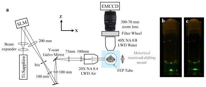
Schematic of the Bessel two-photon light-sheet microscope. (a) Optical setup. The beam path illustrated in the figure is for the case of a uniform phase pattern on the SLM. (b) Two-photon emission from a cuvette of fluorescein solution under a focused Gaussian beam, and (c) under a Bessel beam.
The laser power is typically 100~200 mW on live samples. The beam is translated in Y-axis (perpendicular to the paper in Fig. 1(a)) direction by a galvanometer mirror (Thorlabs). Emission images are collected at 90° to the Bessel beam axis, through a water immersion long working distance objective lens (40X, NA 0.8, Olympus), a zooming tube lens (Sigma Photo, 300-70 mm) and is projected onto an EMCCD (Rolera Thunder, 512-by-512, 16 μm pitch). The sample is mounted in a 0.8-mm ID vertical FEP tube, whose refractive index matches with water. The tube position is controlled by a motorized linear stage, which shifts the sample tube in the z-axis during 3D imaging. Images can be captured at a maximum lateral resolution of 0.5 μm when the tube lens is zoomed to 300 mm, or at 1.1 μm pixel size when the tube lens is zoomed to 70 mm. A high-speed motorized filter wheel is placed in the emission path in order to perform dual-color imaging.
Sample mounting method
Following the standard procedure of preparing live zebrafish embryo for imaging, embryos and larvae were maintained in embryo medium with 0.003% 1-Phenyl-2-thiourea. Animals between 1 to 5 days post fertilization (dpf) were mounted in 0.8-mm ID FEP tubes with embryo medium containing 0.1% low melting point agarose (for increasing the viscosity of the solution) and 200 mg/L tricaine. The tube is plugged with a solid 1% agarose gel plug. The mounting method was proved to be suitable for long time imaging of zebrafish development [12].
A previously reported live animal study with one-photon light-sheet imaging showed that the refractive index of the FEP tube matches well with water in the visible spectrum, and mounting with the FEP tube is suitable for high resolution imaging [12]. We found that the optical property of the FEP tube in the IR range also matches with water well at wavelengths around 800 nm. The Bessel beam maintains a strong and long two-photon excitation line in FEP tubes filled with dye solution [Fig. 2(a) ], showing no degradation caused by astigmatism, which would be the case if the FEP tube does not index-match with water. No measurable two-photon excitation was observed in the walls of the FEP plastic.
Fig. 2.
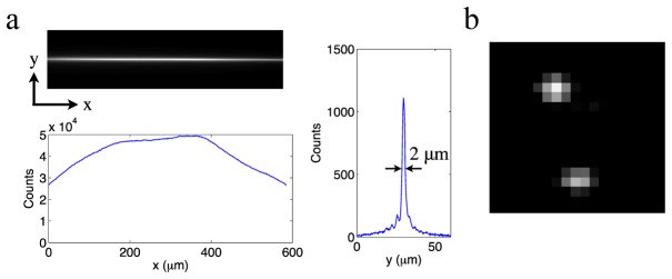
Experimental resolution calibration. (a) Field uniformity over a 600-μm span and 2 μm axial resolution, measured by imaging a fluorescein-filled FEP tube under a stationary Bessel beam. (b) Diffraction limited 0.5 μm lateral resolution, measured by imaging 20-nm diameter beads at 0.27 μm per pixel.
Resolution characterization
The z-axial resolution of the system was measured by imaging a fluorescein-filled FEP tube under a stationary Bessel beam. The two-photon emission has over 50% uniformity over a 600-μm span [Fig. 2(a)], which matches the field-of-view of the camera with a zoomed-out tube lens. The width of the main-band signal is 2 μm, indicating the light sheet will have an excitation thickness of 2 μm (z-axial resolution) when the beam scans in the y direction (vertical direction). The x-y lateral resolution of the system was measured by imaging 20-nm diameter green fluorescent beads (Invitrogen) embedded in 1% agarose gel with scanning light-sheet illumination. The image of single beads shows a diffraction-limited 0.5 μm point spread function [Fig. 2(b)]. Axial and lateral resolutions of our system and an earlier two-photon Bessel light-sheet system are similar [7], because both systems use the same illumination and image capturing NAs. The achieved field-of-view is twice of the earlier system. The doubled field-width was achieved by filling the aperture of an SLM that is twice as wide as what was used in the previous report. The wider field-of-view allows imaging across the entire body of live zebrafish embryos.
Deep penetrating large field-of-view light-sheet imaging in live zebrafish
Large volume 3D image with single-side illumination and emission view
Benefitted from its long depth-of-focus and self-healing property, the Bessel beam penetrates tissue as thick as the entire 600-μm-wide field-of-view. Single-side illumination is sufficient for visualizing GFP-labeled vasculatures across the entire zebrafish larva head. Figure 3 shows selected slices of the 3D image stack (Media 1 (9.6MB, MP4) ) from a transgenic (kdrl:GFP) zebrafish. The image stack was taken with the dorsal surface parallel and closer to the imaging objective lens. The illumination was projected from the right lateral side of the fish (left side of Figs. 3(a)-3(e)). Vessel structures are seen with high clarity from the lateral surface to more than 300 μm deep. The zebrafish heart, which is located on the ventral side of the fish, is visible through more than 500-μm thick tissue.
Fig. 3.
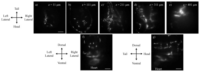
3D two-photon imaging of the entire vasculature of a transgenic Tg(kdrl:GFP) zebrafish head at 3 days post fertilization (dpf). The fish vasculature is labeled with GFP. (a-e) Selected x-y plane slices of two-photon Bessel light-sheet images. (f) x-z plane cross section of the 3D image stacks (g) y-z plane cross section of the 3D image stack. The full image set (512 × 512 × 577) can be viewed in Media 1 (9.6MB, MP4) . 3D images were acquired by moving the sample tube at a Nyquist sampling density of 1-μm per z step, with the imaging plane moving deeper into the fish as z increases (tube moves toward camera). The tube lens focal length was set to 70 mm, resulting in a lateral pixel size of 1.1 μm. The expose time was 1s per step. Scale bar: 100 μm.
The two-photon image is dimmer in the side opposite to the illumination, indicating that the two-photon excitation strength decays as the Bessel beam travels in the tissue. The decay of two-photon excitation are caused by tissue absorption and scattering [7]. Tissue absorption could be dramatically reduced in genetically modified transparent animals, for example the Casper zebrafish [13]. Tissue scattering potentially could be compensated for by adaptive optics [14].
3D cellular imaging
The maximum lateral resolution of the microscope is 0.5 μm, enough for resolving cellular structures. Figure 4(a) and Media 2 (7.8MB, MP4) are 3D rendered images of vasculatures in the tail, showing individual endothelial cells and their organization in 3D. Selected cross sections in the y-z and x-z plane are shown in Figs. 4(b) and 4(c).
Fig. 4.
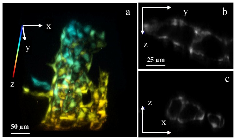
Cellular 3D imaging by two-photon Bessel light-sheet microscope. (a) 3D rendered image of epithelial cells forming vasculature in a Tg(kdrl:GFP) zebrafish tail. The 3D image is color-coded in z-axis. (b) Cross section in the y-z plane and (c) in the x-z plane, showing vessel structures. Full 3D image (512 × 512 × 88) can be viewed in Media 2 (7.8MB, MP4) . 3D images were acquired in 1-μm z-steps by moving the sample tube, with the imaging plane moving deeper into the fish as z increases. The tube lens focal length was set to 300 mm, resulting in a lateral pixel size of 0.27 μm. The exposure time was 1s per step.
Video rate two-photon imaging of heartbeat and blood cell circulation
Bright two-photon emission excited by the Bessel light-sheet makes it possible to image transgenic markers at video rate. Figure 5 shows video frames of one heartbeat cycle of a transgenic Tg(kdrl:GFP) zebrafish (Media 3 (3.7MB, MP4) ), taken from the lateral view at 25 frames per second. The heartbeat was measured at a normal rate of 167 beats per minute. The normal heartbeat indicates that neither the Bessel light-sheet nor the liquid mounting method cause immediate stress to the animal. Because a small fraction of blood cells in the transgenic zebrafish express GFP, occasionally, fluorescent blood cells can be seen passing through the heart chamber (green arrows in Fig. 5).
Fig. 5.
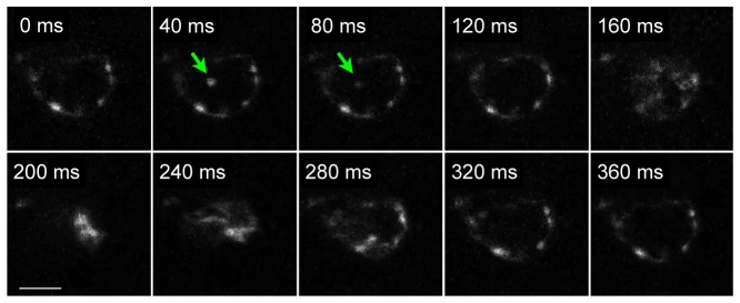
Video rate two-photon images of heartbeat and blood cell (green arrows) circulation in live Tg(kdrl:GFP) zebrafish at 2-3dpf. The video was taken with the tube lens at f = 70mm and a lateral pixel size of 1.1 μm. Areas outside of the heart were chopped in the figure. Full size video (512 × 512) is provided as Media 3 (3.7MB, MP4) . Scale bar: 50 μm.
Long time 3D imaging
The two-photon light sheet microscope imaging causes no observable photon toxicity to embryos and early larvae up to 5dpf. Figure 6 plots a series of 3D rendered images of tail vasculature, taken during a 17-hour time lapse imaging at room temperature. The full 17-hour series can be viewed in Media 4 (422.6KB, MP4) . 3D image volumes were taken every 30 minutes. The image series show normal vasculature development in the tail, proving that long-time imaging did not cause abnormal development of the vasculature system.
Fig. 6.
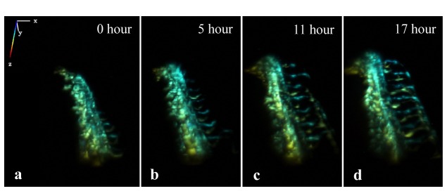
Long time time-lapse images of vasculature development in fish tail, starting at 1 dfp. The 3D image is color-coded in z-axis. The full image series are shown in Media 4 (422.6KB, MP4) .
Diffusion reduction in deep tissue images
The wide and deep-penetrating light-sheet excitation makes it possible to illuminate deep organs surrounded by tissue thicker than 200 μm. At such depth, acquired images are strongly blurred by tissue scattering of emission photons. As seen in Fig. 3, light-sheet images beyond 200 μm depth gradually lose image contrast and effective resolution, indicating that the emission light propagation is reaching the ballistic transport limit. The blurring significantly affects the observation of deep organs with dense structures, for example the zebrafish kidney.
The zebrafish kidney is located in the center of the fish body and its renal glomeruli structures are not fully developed until about 4 dpf, by which time the outer layer of the kidney is 200 μm or more beneath the fish skin from all sides. 1-Phenyl-2-thiourea treatment, a standard practice for delaying pigmentation in zebrafish imaging study, starts losing its effect at 3 dpf. At 4 dpf, strong tissue scattering due to the thickness of the tissue and the increasing amount of pigmentation makes it extremely challenging to observe the cellular structures of the kidney in live intact larvae.
We thus applied nonlinear structured illumination microscopy in the two-photon Bessel light-sheet system in order to reduce diffused photons and retain cellular resolution in images of deep dense tissue.
Nonlinear structured illumination microscopy
A stripe-pattern light-sheet is generated by hopping the Bessel beam in uniform steps during sheet scan in y (vertical) direction. Due to the narrowness of the Bessel beam and two-photon excitation, the effective excitation pattern is highly nonlinear and can be written as
| (1) |
where is the spatial frequency vector of the hopping step, and is the complex harmonics order coefficient, which depends on the contrast, profile and phase of the illumination pattern and can be obtained by imaging a homogeneous sample. The image under the excitation pattern is therefore
| (2) |
where is the emission signal and is the point spread function of the imaging system.
When the photon emission is subjected to tissue scattering, the emission signal is split into a ballistic signal and a diffused signal, and the acquired image becomes
| (3) |
where is the point spread function induced by scattering. In the Fourier space, the acquired image is
| (4) |
where OTF is the optical transfer function of the imaging system, and OTFs is the optical transfer function of tissue scattering. By the principle of nonlinear SIM, if 2N + 1 frames of images are taken with the illumination pattern phase shifted by between each exposure, all orders of the underlined term in Eq. (4) can be reconstructed [10, 15, 16]. Each order represents a frequency-shifted Fourier image of the emission image.
In non-zero orders of these Fourier images, the emission signal is shifted to higher spatial frequencies by nk 0, as illustrated in Fig. 7(a) . The scatter OTFs, also illustrated in Fig. 7(a), is a low-pass filter and remains at near zero frequency. The diffused signal is therefore filtered out by OTFs. However, when the diffused signal is strong, a residue may still exist in the reconstructed Fourier image [Fig. 7(b)]. The next step of the standard SIM reconstruction algorithm shifts the frequency center of the Fourier image back to zero [Fig. 7(c)], followed by inverse Fourier transform to obtain the reconstructed image, which should be mostly free of diffused photons.
Fig. 7.
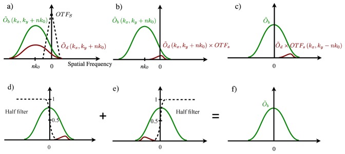
Nonlinear SIM Imaging processing steps to remove strong diffused background in light-sheet imaging of deep tissue structures. Matlab script for the non-linear SIM reconstruction algorithm is provided in Media 5 (15.6KB, PDF) .
When diffused photon signal is strong, residue diffusion signal on one side of the spatial spectrum may be above the noise floor [Fig. 7(c)]. The asymmetrical spectral residue creates two artifacts: first, the spatial image obtained by inverse Fourier transform is no longer real valued; and second, the absolute value of the spatial image can have stripe-shape artifact due to the residue peak at the spatial frequency of -nk 0. These diffusion-induced artifacts may not be visible when the diffusion background comes from weak side-band excitation of the Bessel light-sheet [11]. When performing light-sheet imaging at extreme depth, diffused signal can be stronger than the ballistic signal and these artifacts can be severe.
The diffusion-induced SIM artifacts can be removed by an improved SIM algorithm. Instead of using the complete Fourier image set to reconstruct the final image, the algorithm merges two diffusion-free halves of two Fourier images together, reconstructed from –n [Fig. 7(d)] and + n orders [Fig. 7(e)] respectively. Because images and PSF are both real-valued functions, left and right halves of Fourier images from –n and + n orders are naturally conjugated:
| (5) |
Thus, a real-value filter function ramping from 0 to 1 can seamlessly merge two halves together. The resulting Fourier image [Fig. 7(f)] is diffusion-free and artifact-free. Typically a half Hann ramping curve with a 100% cut-off at ± nk 0/2 is used to avoid ringing artifacts.
With the improved nonlinear SIM method, each of the + n and –n Fourier pair produces a fully reconstructed diffusion-free image. The 0th order Fourier image data is discarded, as its diffused photon background signal is impossible to remove. After optimization of the nonlinear SIM described in the following section, a 5-step phase shift SIM scan was chosen for our experiments. The imaging processing produces two diffusion-free images from 1st and 2nd order pairs respectively. The image merged from 2nd order Fourier images has better diffusion rejection but with a lower SNR due to a weaker harmonic coefficient a 2. A final image is produced by a weighted overlay of images from the 1st and 2nd order reconstruction, with the 1st order result weighted more heavily. The weighting ratio is chosen based on SNR of the two orders in order to achieve a balance between diffusion reduction and SNR.
Like all nonlinear SIM reconstructed images, the final image has a Fourier bandwidth extended by Nk 0 in the y-axis direction, which increases the imaging resolution in the y-axis beyond the diffraction limit. In our case, the pattern period is typically 11.2 μm and the pattern spatial vector k 0 is much smaller than the diffraction limit. The effect of superresolution is not significant.
It is worth noting that confocal line-detection [7] will cause stripe-shaped artifacts in deep light-sheet images due to incomplete filtering of diffused background photons. Because confocal line-detection applies a one-dimensional spatial filter in the light-sheet image, diffusion along the laser line direction is not filtered. In contrast, nonlinear SIM reconstructed images can be artifact-free if the modified algorithm is used, because in SIM the filter that removes diffusion is the optical transfer function of tissue scattering OTFs, which is isotropic in all directions.
The Matlab script for the modified non-linear SIM image reconstruction algorithm is provided in Media 5 (15.6KB, PDF) .
Optimizing structured illumination parameters
Under the two-photon excitation, a highly nonlinear periodic excitation pattern [Fig. 8(a) ] is generated by hopping the laser beam scanner in fixed steps. The phase of the pattern can be adjusted by changing the initial position of the laser beam scanner, and the pattern period is controlled by the hopping step size. Figure 8(b) plots the spatial power spectra of an excitation pattern, taken from a fluorescein solution sample. High order harmonics of the excitation pattern are prominent.
Fig. 8.
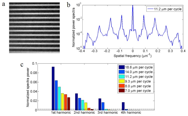
Optimizing structured illumination. (a) two-photon image from a fluorescein solution sample, showing a typical structured excitation pattern. (b) Normalized spatial power spectrum of two-photon excitation patterns showing high order harmonics of the pattern. (c) Normalized spectra powers at different harmonic orders of the excitation pattern with different pattern period. The dashed line is the typical noise level of light-sheet images deep inside zebrafish.
The pattern period was chosen based on three constrains:
-
(1)
Uniform effective illumination: In non-linear SIM, the pattern’s phase shift step has to be small enough, so that the sample gets effectively a uniform illumination after a complete exposure sequence. Otherwise the reconstructed image will suffer from artifacts. The Fourier domain explanation to this requirement is that a wide and highly nonlinear pattern will have strong harmonic signal to the (N + M) order. If only (2N + 1) phase steps are taken, the reconstruction process will mistakenly ignore higher orders harmonics from N + 1 to N + M. The resulting image will therefore be incorrect. The noise level plays an important role in determining the maximum order to be solved and the number of phase-shift steps needed. The structured excitation pattern in Fig. 8(a) was acquired with a bright fluorescence solution sample, which shows multiple orders of harmonics in its power spectrum [Fig. 8(b)]. Under practical imaging noise level (dashed line in Fig. 8(c)), all harmonic orders above the noise level need to be considered for artifact free image reconstruction. If the illumination pattern has a period less than 14 μm, harmonic orders above the 3rd can be ignored. Similarly pattern periods need to be less than 11.2 μm and 7.0 μm in order to ignore harmonics above the 2nd and 1st order respectively.
-
(2)
High pattern contrast: The pattern period of incoherent SIM needs to be reasonably large in order to achieve a high pattern contrast. Shorter pattern period leads to a reduction in pattern contrast, which results in lower strengths of the harmonic orders [Fig. 8(c)] and a loss of SNR in the reconstructed image. Incoherent SIM, unlike interference SIM, cannot reach 100% pattern contrast. The structured illumination pattern period in incoherent SIM will need to be much wider than the width of the point spread function to maximize contrast.
-
(3)
Image acquisition time. In theory, a wider pattern with higher order harmonics will not only improve diffusion reduction and pattern contrast, but also produce a more significant superresolution effect. However, because higher-order SIM requires more frames and longer acquisition time, there is a practical limit on the highest harmonics orders that can be measured.
Considering image acquisition time constraint, 2nd order non-linear SIM with 5 phase steps was chosen for in vivo two-photon imaging of developing embryos and larvae in our system. Linear SIM, although only needs 3-phase acquisition, requires a 7.0 μm period pattern with significantly weaker signal strength at the 1st harmonic order, whereas 3rd order nonlinear SIM requires 7 exposures per sequence. Among pattern periods (8~11.2 μm) that are suitable for 5-phase acquisition, the 11.2-μm pattern period provide the strongest pattern harmonic orders. Under such condition, the two-photon excitation pattern has a 60% contrast; meaning 60% of photons is utilized in the SIM reconstruction algorithm, whereas 40% of photons are discarded in the form of 0th order image. Merging of 5 phase-shifted two-photon excitation patterns yields an effective illumination with <2% residue periodic contrast, confirming that the 11.2-μm pattern 5-phase illumination can uniformly illuminate the light-sheet plane.
Restoring cellular resolution in deep tissue light-sheet images
Figure 9 demonstrates the diffusion reduction process in deep tissue two-photon Bessel light-sheet imaging. Figure 9(a) is an in vivo light-sheet image of glomerulus structures, taken from a 4 day-post-fertilization (dpf) live transgenic Tg(pod:NTR-mCherry) zebrafish larva at about 250-μm deep from the fish skin. Under uniform light-sheet illumination [Fig. 9(a)], the image, although has decent fluorescence signal, is severely blurred by tissue scatter.
Fig. 9.
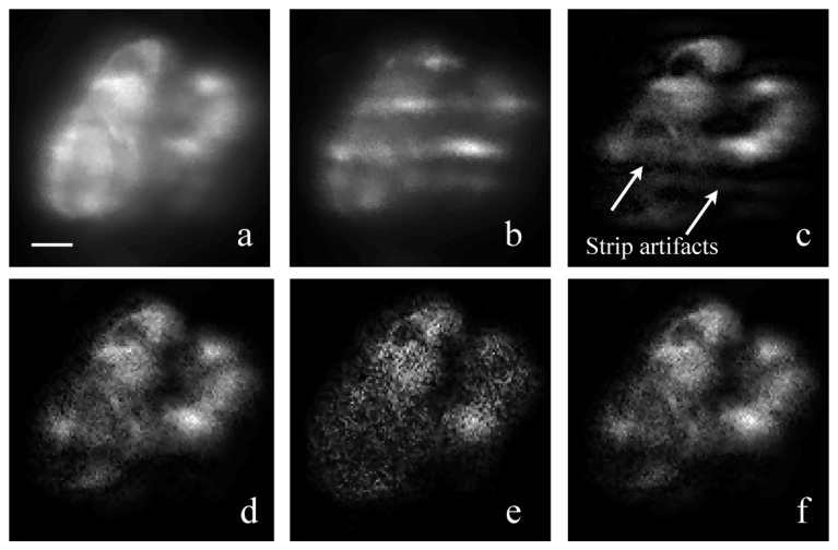
Diffusion reduction with a modified SIM reconstruction algorithm. (a) Merged image of 5 SIM raw frames with phase-shifted patterns. The merged image is equivalent to a 10-seconds-exposure image under uniform light-sheet. (b) Raw image frame under structured light-sheet illumination; the expose time was 2s; (c) Reconstructed image by the standard SIM algorithm, showing stripe-shaped artifacts due to residual diffusion background; (d) Reconstructed image from ± 1 order harmonics by the improved SIM algorithm. Stripe-shape artifacts were removed; (e) Reconstructed image from ± 2 order harmonics by the improved SIM algorithm; (f) Weighted merge of ± 1 and ± 2 order reconstructed image. All images were taken from the kidney of a live transgenic Tg(pod:NTR-mCherry) zebrafish at 4 dpf. Podocytes in the fish kidney is labeled with mCherry. Images was taken with the tube lens at f = 135mm and a lateral pixel size of 0.6 μm. The scale bar is 10 μm.
With a 5-phase structured illumination pattern and the standard nonlinear SIM reconstruction algorithm, the blurry background due to diffusion is removed from the raw structured illumination images [Fig. 9(b)] and the clarity of the reconstructed image [Fig. 9(c)] is greatly improved. However, strong stripe-shaped artifacts are also seen in the reconstructed image. The improved non-linear SIM reconstruction algorithm removes these artifacts [Figs. 9(d) and 9(e)]. Of the two reconstructed images, the result from ± 1 orders has better SNR. The final image [Fig. 9(f)] is a weighed merge of the two orders, with the 1st order result weighed twice more than the 2nd order.
The final image exhibits lower SNR than the equivalent uniform-illumination image. The reason of the low SNR is due to two factors: (1) At lease 40% of photons are discarded due to the 60% pattern contrast, however 100% of the shot noise remains. (2) SIM filters out diffused photon signals through spatial spectra manipulation, but the white-spectrum shot-noise associated with diffused photons remains. In other words, SIM filters out the unwanted signal, but not the photon shot-noise associated with the unwanted signal.
Mathematically, the SIM image is reconstructed by linear mixing of raw images taken under phase-shifted illumination [10, 15, 16], thus the noise level in a SIM image has
| (6) |
where T is the total exposure time, and ntotal is the total photon flux. The ballistic signal of a SIM image has
| (7) |
where nb is the ballistic photon flux, and an is the harmonic strength. Since an is linear to the pattern contrast, the SNR of SIM reconstructed image follows
| (8) |
where m is the illumination pattern contrast. nb and ntotal are not necessarily correlated in space, because in dense structures the ballistic photon signal at one location can be overwhelmed by diffused photons from adjacent locations. In the final SIM image, the visibility of one structure can be affected by the noise of the diffused photon signal originated from adjacent structures, which needs to be reduced with longer exposures. The SIM image in Fig. 9(f) was reconstructed with an exposure time twice of the typical time used to acquire images from surface layers using the uniform light-sheet.
3D two-color cellular image of deep organ
The two-photon Bessel light-sheet SIM microscope and the improved nonlinear SIM algorithm were applied to imaging cellular structures of zebrafish kidney at 4 dpf in double transgenic fish Tg (pod:NTR-mCherry; kdrl:GFP) [17]. The double transgenic fish has GFP-expressing endothelial cells and mCherry-expressing renal podocytes. Under uniform light-sheet, 3D images show highly blurred structures, especially in densely structured glomeruli [Figs. 10(a) , 10(c) and 10(e)]. With SIM, individual podocytes are visible [Fig. 10(b)], and cross section images clearly show podocytes wrapping around endothelial cells in vasculature [Figs. 10(d) and 10(f)]. The full 3D data sets are shown in Media 6 (3.1MB, MP4) for uniform illumination and Media 7 (2.9MB, MP4) for SIM.
Fig. 10.
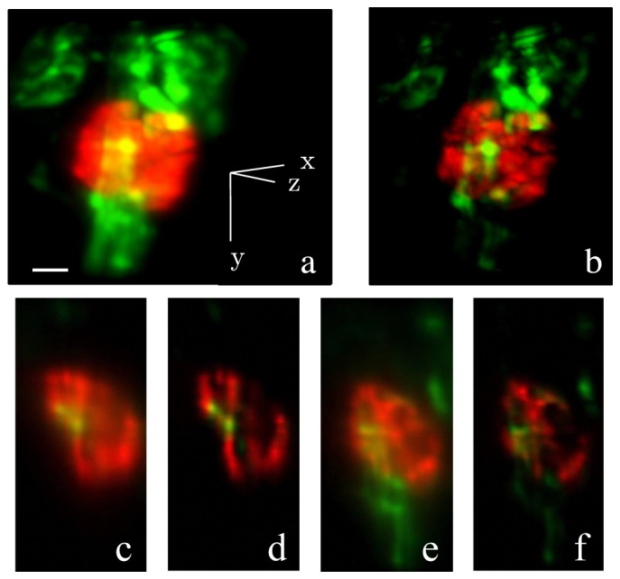
3D two-color images of kidney cellular structure of a live double transgenic zebrafish larva at 4dpf. GFP (green) labels endothelial cells in the vasculature. mCherry (red) labels podocytes. (a) Maximum intensity projection of 3D image set taken with a uniform light-sheet (full image set (256 × 256 × 68) in Media 6 (3.1MB, MP4) ); (b) Maximum intensity projection of diffusion-free 3D image set obtained with structured light-sheet (full image set (256 × 256 × 68) in Media 7 (2.9MB, MP4) ); (c) A x-z plane cross section (anterior view) of the 3D image taken with a uniform light-sheet (d) Same cross section as (c), taken with structured light-sheet; (e) A y-z plane cross section (lateral view) of the 3D image taken with a uniform light-sheet; (f) Same cross section as (e), taken with structured light-sheet. The scale bar is 20 μm.
Summary
Challenges in deep tissue fluorescence light-sheet imaging are two-fold. In order to obtain a clear image in deep layers of biological samples, one needs to effectively deliver excitation deep into a sample, and at the same time filter out diffused fluorescence emission photon signals. In the two-photon Bessel light-sheet nonlinear SIM, the delivery of excitation is enhanced by two-photon excitation and the non-diffractive Bessel beam. A wide field-of-view and superior excitation penetration allows effective illumination of large and deep organs in live embryos and larvae. Diffused photon emission is then filtered out by a structured light-sheet illumination and an improved nonlinear SIM algorithm. By addressing the deep tissue imaging challenges in both excitation and emission paths, two-photon Bessel light-sheet SIM provides a noninvasive tool for deep organ imaging at cellular level resolution in live animals.
Acknowledgments
This research was supported by NIH grants to L. P. (R00EB008737, R01EB015481 and R21EB012646). W.Z. was supported by grants from NIH (R00DK091405, P30DK081943) and American Society of Nephrology (Carl W. Gottschalk Research Scholar Grant).
References and links
- 1.Huisken J., Swoger J., Del Bene F., Wittbrodt J., Stelzer E. H., “Optical sectioning deep inside live embryos by selective plane illumination microscopy,” Science 305(5686), 1007–1009 (2004). 10.1126/science.1100035 [DOI] [PubMed] [Google Scholar]
- 2.Keller P. J., Schmidt A. D., Wittbrodt J., Stelzer E. H. K., “Reconstruction of zebrafish early embryonic development by scanned light sheet microscopy,” Science 322(5904), 1065–1069 (2008). 10.1126/science.1162493 [DOI] [PubMed] [Google Scholar]
- 3.Krzic U., Gunther S., Saunders T. E., Streichan S. J., Hufnagel L., “Multiview light-sheet microscope for rapid in toto imaging,” Nat. Methods 9(7), 730–733 (2012). 10.1038/nmeth.2064 [DOI] [PubMed] [Google Scholar]
- 4.Tomer R., Khairy K., Amat F., Keller P. J., “Quantitative high-speed imaging of entire developing embryos with simultaneous multiview light-sheet microscopy,” Nat. Methods 9(7), 755–763 (2012). 10.1038/nmeth.2062 [DOI] [PubMed] [Google Scholar]
- 5.Truong T. V., Supatto W., Koos D. S., Choi J. M., Fraser S. E., “Deep and fast live imaging with two-photon scanned light-sheet microscopy,” Nat. Methods 8(9), 757–760 (2011). 10.1038/nmeth.1652 [DOI] [PubMed] [Google Scholar]
- 6.Fahrbach F. O., Simon P., Rohrbach A., “Microscopy with self-reconstructing beams,” Nat. Photonics 4(11), 780–785 (2010). 10.1038/nphoton.2010.204 [DOI] [Google Scholar]
- 7.Fahrbach F. O., Gurchenkov V., Alessandri K., Nassoy P., Rohrbach A., “Light-sheet microscopy in thick media using scanned Bessel beams and two-photon fluorescence excitation,” Opt. Express 21(11), 13824–13839 (2013). 10.1364/OE.21.013824 [DOI] [PubMed] [Google Scholar]
- 8.Neil M. A., Juskaitis R., Wilson T., “Method of obtaining optical sectioning by using structured light in a conventional microscope,” Opt. Lett. 22(24), 1905–1907 (1997). 10.1364/OL.22.001905 [DOI] [PubMed] [Google Scholar]
- 9.Keller P. J., Schmidt A. D., Santella A., Khairy K., Bao Z., Wittbrodt J., Stelzer E. H. K., “Fast, high-contrast imaging of animal development with scanned light sheet-based structured-illumination microscopy,” Nat. Methods 7(8), 637–642 (2010). 10.1038/nmeth.1476 [DOI] [PMC free article] [PubMed] [Google Scholar]
- 10.Gustafsson M. G., “Nonlinear structured-illumination microscopy: Wide-field fluorescence imaging with theoretically unlimited resolution,” Proc. Natl. Acad. Sci. U.S.A. 102(37), 13081–13086 (2005). 10.1073/pnas.0406877102 [DOI] [PMC free article] [PubMed] [Google Scholar]
- 11.Gao L., Shao L., Higgins C. D., Poulton J. S., Peifer M., Davidson M. W., Wu X., Goldstein B., Betzig E., “Noninvasive imaging beyond the diffraction limit of 3D dynamics in thickly fluorescent specimens,” Cell 151(6), 1370–1385 (2012). 10.1016/j.cell.2012.10.008 [DOI] [PMC free article] [PubMed] [Google Scholar]
- 12.Kaufmann A., Mickoleit M., Weber M., Huisken J., “Multilayer mounting enables long-term imaging of zebrafish development in a light sheet microscope,” Development 139(17), 3242–3247 (2012). 10.1242/dev.082586 [DOI] [PubMed] [Google Scholar]
- 13.White R. M., Sessa A., Burke C., Bowman T., LeBlanc J., Ceol C., Bourque C., Dovey M., Goessling W., Burns C. E., Zon L. I., “Transparent adult zebrafish as a tool for in vivo transplantation analysis,” Cell Stem Cell 2(2), 183–189 (2008). 10.1016/j.stem.2007.11.002 [DOI] [PMC free article] [PubMed] [Google Scholar]
- 14.Débarre D., Botcherby E. J., Watanabe T., Srinivas S., Booth M. J., Wilson T., “Image-based adaptive optics for two-photon microscopy,” Opt. Lett. 34(16), 2495–2497 (2009). 10.1364/OL.34.002495 [DOI] [PMC free article] [PubMed] [Google Scholar]
- 15.Heintzmann R., “Saturated patterned excitation microscopy with two-dimensional excitation patterns,” Micron 34(6-7), 283–291 (2003). 10.1016/S0968-4328(03)00053-2 [DOI] [PubMed] [Google Scholar]
- 16.Zhang H., Zhao M., Peng L., “Nonlinear structured illumination microscopy by surface plasmon enhanced stimulated emission depletion,” Opt. Express 19(24), 24783–24794 (2011). 10.1364/OE.19.024783 [DOI] [PMC free article] [PubMed] [Google Scholar]
- 17.Zhou W., Hildebrandt F., “Inducible podocyte injury and proteinuria in transgenic zebrafish,” J. Am. Soc. Nephrol. 23(6), 1039–1047 (2012). 10.1681/ASN.2011080776 [DOI] [PMC free article] [PubMed] [Google Scholar]


