Abstract
We present the theoretical basis and experimental verification for cardiac output measurements using noninvasively measured hemodilution curves afforded with an indicator dilution technique and the emerging photoacoustic technology. A photoacoustic system noninvasively tracks a transient hemodilution effect induced by a bolus of isotonic saline as an indicator. As a result, a photoacoustic indicator dilution curve is obtained, which allows to estimate cardiac output from the developed algorithm. The experiments with a porcine blood circulatory phantom system demonstrated the feasibility of this technology towards the development of a noninvasive cardiac output measurement system for patient monitoring.
OCIS codes: (170.0170) Medical optics and biotechnology, (170.3890) Medical optics instrumentation, (170.5120) Photoacoustic imaging, (170.4580) Optical diagnostics for medicine, (170.3880) Medical and biological imaging
1. Introduction
Cardiac output (CO) is an established important physiological parameter that enables physicians to optimize fluid status in hemodynamically instable and critically ill patients, such as to improve the patient outcomes [1, 2]. Conventional technologies for measuring CO involve using indicator dilution techniques [3–6]. In these techniques, a bolus of indicator, such as cold saline, is typically introduced into a patient’s central circulation through a central venous catheter or pulmonary arterial catheter (PAC). An indicator dilution curve is measured downstream with a highly invasive femoral arterial catheter [7] or the distal port of the PAC [8] as the indicator is washed out in the patient’s circulation system, which is used to calculate the patient’s CO [3, 4, 6]. However, since the established indicator dilution methods for the estimation of CO are highly invasive and potentially cause medical complications, there is an increasing need for developing noninvasive devices [9, 10] to assess CO in critically ill patients. In this paper, we report breakthroughs of developing a noninvasive cardiac output measurement technology by combining the indicator dilution technique with the emerging noninvasive photoacoustic technology [11–14].
In this proposed technology, a small bolus of room temperature isotonic saline is injected quickly into the central circulation of a patient as the indicator, which induces a transient hemodilution effect. A photoacoustic sensor equipped with a single ultrasound sensor is placed downstream over a tissue bed with a superficial artery. The sensor noninvasively measures the transient hemodilution effect from an artery as the indicator travels across the sensor site. As the indicator is washed out in the circulation system, a hemodilution (indicator dilution) curve is noninvasively measured, which is used to derive hemodynamic parameters, such as CO.
2. Theory
A photoacoustic signal is a linear function of a hemoglobin concentration in the blood when a tissue bed containing a superficial blood vessel is illuminated by a light source with a wavelength within the range of 600-1000 nm [15], where the product of the blood absorption coefficient and the vessel diameter is much less than 1 [16]. As a result, when a bolus of isotonic saline is injected into the blood stream, the hemoglobin concentration of the blood will be diluted, which induces photoacoustic signal variation, consequently resulting in an indicator dilution curve. When a bolus of an isotonic saline with amount of is instantaneously injected at t = 0 (i.e., the time of starting the injection is set to zero for convenience without losing the generality) into a circulation system, as the indicator is being washed out of the circulation system, CO can be calculated from the resultant indicator dilution curve by [3],
| (1) |
where and are blood and isotonic saline volumes passing through the measurement point of the blood vessel during the unit time interval, , respectively. Note that during is always constant for constant CO, which contains for the case of indicator dilution. Equation (1) indicates that the whole isotonic saline injectate is completely washed out of the circulation system as time goes to infinity assuming that no isotonic molecules interact with tissues outside the cardiovascular system.
As above mentioned, for a fixed amount of incident beam onto the measurement site, the photoacoustic signal is proportional to the total hemoglobin concentration in the unit blood volume . Therefore, for the stationary state before indicator injection, the photoacoustic signal measured from the targeted arterial vessel could be described by
| (2) |
where indicates the total hemoglobin in the blood volume associated with . The subscribe b indicates the background that means before the indicator injection. The termΚ is the conversion factor from to the photoacoustic signal, which is assumed to be a constant during the measurement of photoacoustic indicator dilution curves. The conversion factor accommodates systematic effects, such as a sensitivity of an ultrasound transducer and/or unknown blood vessel wall effect. If this measurement happens in a clinical situation, the factor might also include an effect of an unknown optical property of a background tissue bed. The term represents the photoacoustic signal from all other photoacoustic sources insensitive to hemoglobin concentration variation induced by the injected indicator. At the measurement site after the injection, the amount of hemoglobin in is decreased due to the added portion of the isotonic solution. Therefore, the PA signal variation due to injected isotonic solution can be described as
| (3) |
where andis the volume of the blood not diluted by any portion of an injected isotonic solution. Because the hemoglobin concentration in pure blood is not changed before and after the indicator injection, it is valid to write
| (4) |
Although the amount of volume of is the same as that of for the same blood vessel and constant CO, they contain different amount of hemoglobin. By substituting Eq. (4) to Eq. (3), the photoacoustic signal variation during the dilution process, is
| (5) |
Considering Eq. (2), Eq. (5) is further developed to
| (6) |
where
| (7) |
Integrating both sides of Eq. (6) in time with the consideration of Eq. (1) derives the blood flow rate as
| (8) |
In the derivations from Eqs. (5) to (8), it is assumed that and are stationary in time during photoacoustic indicator dilution measurements. In Eq. (8), both and are measurable and the amount of isotonic injection is also known. The term αis the only unknown factor on the estimation of CO since it is very difficult to measure , especially in a clinical situation. However, it is reasonable to assume that typically, the from the targeted blood vessel is negligible compared to the main photoacoustic signal with an optical wavelength (600-1000nm) where the dominant absorber is the hemoglobin. Therefore, it would be generally accepted that, which means α ~1. Therefore, we set αto 1 for the estimation of CO from ex-vivo experimental data in this paper.
3. Experimental setup
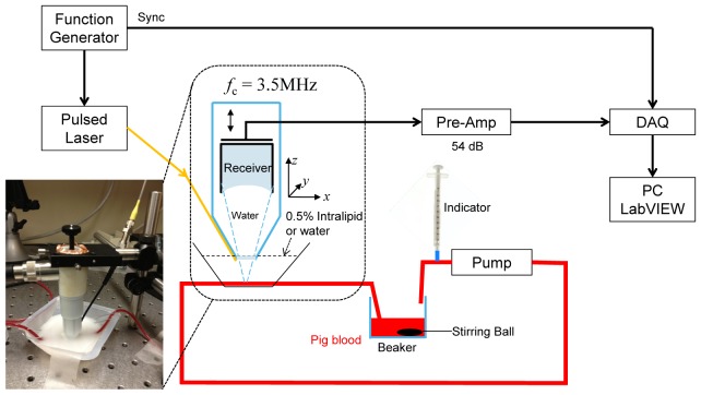
Ex-vivo experiments were performed to demonstrate the concept described in the previous section. Figure 1 shows the schematic of the experimental setup for the measurement of a flow rate (i.e., cardiac output in a human cardiovascular circulatory system).
Fig. 1.
Schematic of the experimental setup for the photoacoustic system to measure the flow rate.
In these experiments, a high power pulsed laser diode at 905 nm (OSI Laser Diode Inc.: CVN 5S63) was used as the light source. The laser diode was driven with a pulse laser diode driver (Laser Component: LSP-40), running at the repetition rate of 3.2 KHz and the pulse width of 100 ns, which delivers a pulse energy of about 6.5uJ to the pig blood in a tube. A function generator (Agilent: 33522A) was used to generate 100 ns pulses to trigger the laser as well as to synchronize the data acquisition system. A photoacoustic sensor equipped with a commercial ultrasound transducer (Olympus Panametrics: NDT C382, 3.5 MHz) and fiber optics was integrated with a home-made spring loaded plastic sensor holder as shown in Fig. 1. In this sensor design, the transducer was resting on a spring, and its focus can be adjusted by turning the screw at the top of the sensor holder. A thin Rexolite disk with low ultrasound attenuation was used to seal the bottom of the plastic sensor holder. This special sensor design not only allows the sensor holder to be filled with water as an ultrasound coupling medium, but also provides a solid ultrasound interface, which makes the sensor portable and easy to use for in-vivo testing with an ultrasound gel. A short plastic fiber was inserted through a hole in the wall of the plastic housing to deliver light to the phantom. A picture of the PA sensor for the bench-top experiment is shown in the inset of Fig. 1. Once the photoacoustic signal was detected by the PA detector, the signal was amplified with a pre-amplifier (Olympus: 5662) and digitized with a high speed digitizer (Gage: CS1642-128M), and acquired into a laptop with the LabVIEW program developed in-house. The acquired PA signals were averaged 800 times in real-time, and digitally band-pass filtered (0.5-5MHz) with the Labview program. The peak-to-peak voltages of the photoacoustic signals were calculated to derive the hemodilution curve.
In order to generate a reliable reference to validate the algorithm, the pump speed was calibrated for the selected flow rates of the pig blood. To obtain the calibration coefficient, the pig blood was first weighted with a digital scale (METTLER PM2000, resolution = 0.01 g) from 1.00 ml to 8.00 ml with an increment of 1.00 ml to obtain its density of (1.036 ± 0.003 g/ml) from the linear regression with the Pearson's correlation coefficient of 0.99998. The same blood was then pumped at discrete pump speed settings (12 to 28 with an increment of 4) to a beaker on the digital scale for 60 seconds and its whole weight was measured. The weight was converted to the volume with the previously measured blood density. Figure 2 shows the calibrated flow rates of the pig blood for the pump with pump speeds setting from 12 to 28.
Fig. 2.
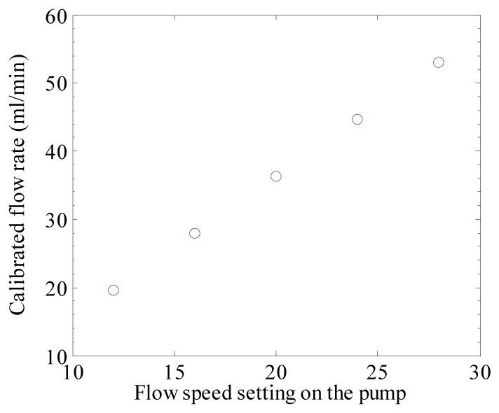
Calibrated flow rates of the pumped circulating pig blood in the bench-top experimental system.
In the experiment, the total volume of the pig blood was 27 ml (10 ml in the beaker plus 17 ml in the tubing). An indicator of 1.00 ml isotonic saline was rapidly injected into the beaker through the blood injection port. In clinical indicator dilution measurements for an adult, the amount of indicator injection could be up to 15ml and the blood volume contained in a heart is 250~300ml. Therefore, the indicator injection ratio in this ex-vivo experiment is similar with that in the clinical situation. When the 1.00 ml isotonic saline indicator was washing through the detecting site at the downstream tube, a photoacoustic hemodilution curve was obtained, which was used to estimate the flow rate. A 0.5% Intralipid solution (Liposym III 20%) was used to mimic skin tissue bed scattering and the tube was positioned about 3 mm below the surface of the Intralipid solution.
4. Results
Figure 3(a) shows an example of a photoacoustic signal measured by the ultrasound transducer focusing on the pig blood tube in the experimental setup of Fig. 1. Temporal variation of the amount of the signal becomes a photoacoustic indicator dilution curve. We averaged 400 photoacoustic signals for a single data point of indicator dilution curves, which means the acquisition rate for measuring the dilution curve is 8Hz for the 3.2kHz pulsed diode laser. For measuring the photoacoustic signal variation, both peak-to-peak and the area under the signal were considered, the results of which are shown in Fig. 3(b). These dilution curves are normalized to 1.0 as the baseline for a comparison. As shown in Fig. 3(b), there is no much difference between two methods of peak-to-peak and area under the signal, so we consider peak-to-peak photoacoustic dilution curves for the estimation of CO.
Fig. 3.
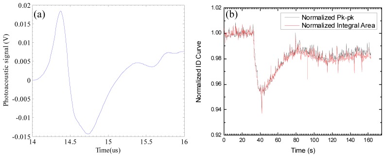
(a) one example of photoacoustic signals from the pig blood tube in the experimental setup. (b) A normalized indicator dilution curves extracted from consecutively measured photoacoustic signals.
In the measured indicator dilution curves, photoacoustic signals are decreased when the diluted blood passes at the measurement site. The second valleys in Fig. 3(b) are caused by the recirculation of the injected isotonic saline indicator, as typically shown in a clinical situation Because of the recirculation, it is impossible to completely measure the tail of the photoacoustic dilution curve for the first circulation. A typical approach for finding the complete dilution curve is to remove the recirculation portion of the curve, and curve-fit the first circulation curve using an exponential model [17], where it is assumed that the tail of dilution curves exponentially changes based on an appropriate model of vascular structures. For the exponential model to estimate CO in this paper, we considered a single blood container mimicking a heart chamber in a cardiovascular structure. Since an indicator dilution decreases the measured photoacoustic signals, the denominator of Eq. (8) indicates the area between the scaled photoacoustic dilution curve, and the normalized baseline 0, as shown in Fig. 4 . Different from other previously known indicator dilution methods [6] for estimating CO, the normalization factor in the integration of Eq. (8) is naturally obtained during the indicator dilution measurement process.
Fig. 4.
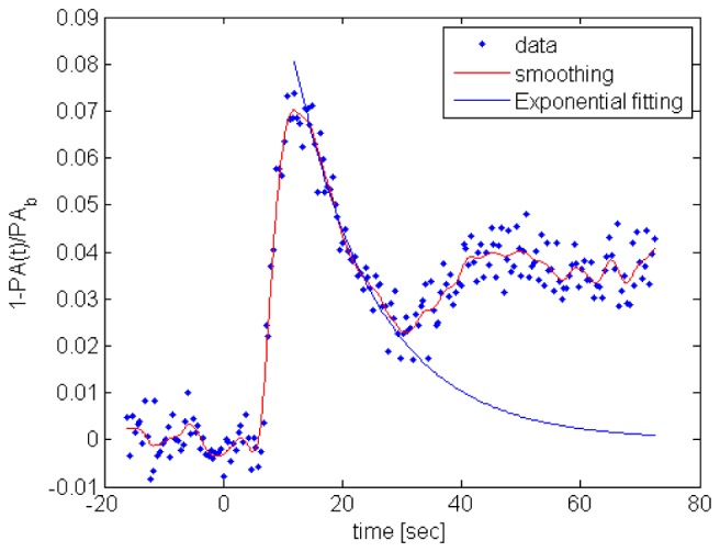
The red curve indicates the smoothed dilution signal after applying an averaging filter. The exponential method estimates the tail of the dilution curve that is shown as the blue curve. The integration in the denominator of Eq. (8) indicates the area under the scaled dilution curve.
Figure 5 shows the estimated flow rates calculated using Eq. (8), where 5 different flow rates were tested. As mentioned before, we performed experiments with water and 0.5% Intralipid as the intermediate medium between the photoacoustic sensor and the pig blood tube, which imitate an ideal no-scattering medium and photon-scattering tissue bed, respectively. Although the experiment with Intralipid is more realistic, we conducted the experiment with water to validate the algorithm of Eq. (8) because the photoacoustic signal is greatly increased with almost no absorption in the water tissue bed, which minimizes the effect of α. As indicated in Fig. 5, the mean and standard deviation for differences between the estimated and actual values are −0.61ml/min and 2.54ml/min for water, and 5.63ml/min and 3.87ml/min for Intralipid. The estimated flow rates for water are highly consistent with the actual values, but the results for 0.5% Intralipid are slightly over estimated. It is conjectured that the over-estimation may be caused by the Intralipid absorption, as observed during the experiments, that indicates α<1 for the actual situation, but we assumed α = 1 in Eq. (8) for the estimation of flow rates. Because there is no clear boundary between and in Eq. (7) and the overall photoacoustic signal is the mixed one, as shown in Fig. 3(a), the contribution of to could be either negative or positive, which means α could be more or less than 1, especially, in a clinical measurement.
Fig. 5.
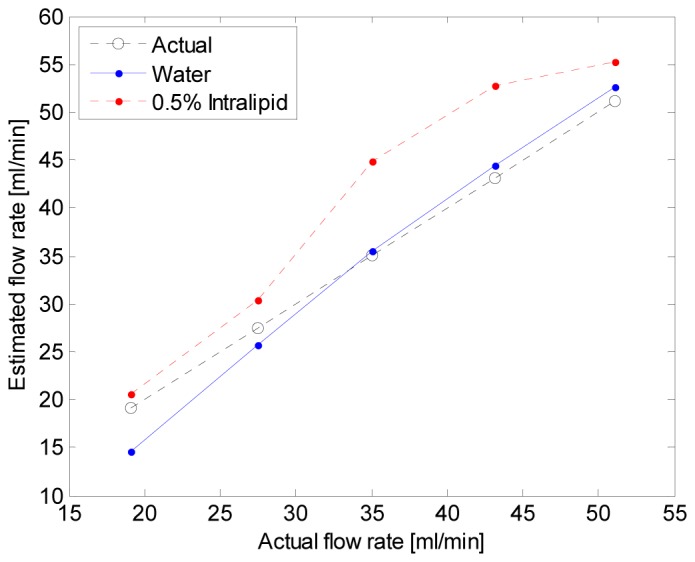
Estimated flow rates from the theory of photoacoustic indicator dilution.
5. Conclusion and discussion
We presented a new concept to noninvasively measure cardiac output by combining a photoacoustic technique and indicator dilution method. The theory was developed to calculate cardiac output from the indicator dilution curves measured by the photoacoustic system. The estimated flow rates from the ex-vivo bench-top experimental data are consistent with actual values with acceptable errors, which validates the feasibility of this technology.
The measurement accuracy of this method and the impact of α have also been studied with in-vivo swine model, and compared with transitional transpulmonary thermo-dilution technique. The results, which will be published elsewhere, demonstrated that this new technology is capable of achieving comparable accuracy with those of the traditional invasive methods.
To further improve the measurement accuracy, different indicators, such as an ICG dye, may be used to strengthen the dilution signal, reducing the adverse effect of the background noise signals. Alternatively, the system imaging resolution may be optimized to minimize the interference of the background signals. In addition, advanced methods for actively reducing or quantifying the amount of α, thus improving the overall measurement performance could be developed in terms of hardware and software. Our future study will be focused on the pre-clinical experiments for this photoacoustic indicator dilution method considering the improvement of clinical measurement accuracy.
Acknowledgment
The authors thank Mr. Charles Haisley for his help on designing the PA sensor holder.
References and links
- 1.Hamilton M. A., Cecconi M., Rhodes A., “A systematic review and meta-analysis on the use of preemptive hemodynamic intervention to improve postoperative outcomes in moderate and high-risk surgical patients,” Anesth. Analg. 112(6), 1392–1402 (2011). 10.1213/ANE.0b013e3181eeaae5 [DOI] [PubMed] [Google Scholar]
- 2.Pearse R., Dawson D., Fawcett J., Rhodes A., Grounds R. M., Bennett E. D., “Early goal-directed therapy after major surgery reduces complications and duration of hospital stay. A randomised, controlled trial [ISRCTN38797445],” Crit. Care 9(6), R687–R693 (2005). 10.1186/cc3887 [DOI] [PMC free article] [PubMed] [Google Scholar]
- 3.Meier P., Zierler K. L., “On the theory of the indicator dilution method for measurment of blood flow and volume,” J. Appl. Phys. 6, 731–744 (1954). [DOI] [PubMed] [Google Scholar]
- 4.Weisel R. D., Berger R. L., Hechtman H. B., “Current concepts measurement of cardiac output by thermodilution,” N. Engl. J. Med. 292(13), 682–684 (1975). 10.1056/NEJM197503272921307 [DOI] [PubMed] [Google Scholar]
- 5.Zierler K., “Indicator dilution methods for measuring blood flow, volume, and other properties of biological systems: a brief history and memoir,” Ann. Biomed. Eng. 28(8), 836–848 (2000). 10.1114/1.1308496 [DOI] [PubMed] [Google Scholar]
- 6.Reuter D. A., Huang C., Edrich T., Shernan S. K., Eltzschig H. K., “Cardiac output monitoring using indicator-dilution techniques: basics, limits, and perspectives,” Anesth. Analg. 110(3), 799–811 (2010). 10.1213/ANE.0b013e3181cc885a [DOI] [PubMed] [Google Scholar]
- 7.A. Genahr, and A. McLuckie, “Tramspulmonary thermodilution in the critically ill,” Brit. J. Inten. Care Spring, 6-10 (2004).
- 8.Chatterjee K., “The Swan-Ganz catheters: past, present, and future. A viewpoint,” Circulation 119(1), 147–152 (2009). 10.1161/CIRCULATIONAHA.108.811141 [DOI] [PubMed] [Google Scholar]
- 9.Benington S., Ferris P., Nirmalan M., “Emerging trends in minimally invasive haemodynamic monitoring and optimization of fluid therapy,” Eur. J. Anaesthesiol. 26(11), 893–905 (2009). 10.1097/EJA.0b013e3283308e50 [DOI] [PubMed] [Google Scholar]
- 10.Marik P. E., “Noninvasive cardiac output monitors: a state-of the-art review,” J. Cardiothorac. Vasc. Anesth. 27(1), 121–134 (2013). 10.1053/j.jvca.2012.03.022 [DOI] [PubMed] [Google Scholar]
- 11.Esenaliev R. O., Petrov Y. Y., Hartrumpf O., Deyo D. J., Prough D. S., “Continuous, noninvasive monitoring of total hemoglobin concentration by an optoacoustic technique,” Appl. Opt. 43(17), 3401–3407 (2004). 10.1364/AO.43.003401 [DOI] [PubMed] [Google Scholar]
- 12.Graham-Rowe D., “Sounding out photons,” Nat. Photonics 3(3), 123–125 (2009). 10.1038/nphoton.2009.7 [DOI] [Google Scholar]
- 13.Pramanik M., Wang L. V., “Thermoacoustic and photoacoustic sensing of temperature,” J. Biomed. Opt. 14(5), 054024 (2009). 10.1117/1.3247155 [DOI] [PMC free article] [PubMed] [Google Scholar]
- 14.Allen T. J., Cox B. T., Beard P. C., “Generating photoacoustic signals using high-peak power pulsed laser diodes,” Proc. SPIE 5696, 233–242 (2005). 10.1117/12.597321 [DOI] [Google Scholar]
- 15.Jacques S. L., “Optical properties of biological tissues: a review,” Phys. Med. Biol. 58(11), R37–R61 (2013). 10.1088/0031-9155/58/11/R37 [DOI] [PubMed] [Google Scholar]
- 16.Banerjee B., Bagchi S., Vasu R. M., Roy D., “Quantitative photoacoustic tomography from boundary pressure measurements: noniterative recovery of optical absorption coefficient from the reconstructed absorbed energy map,” J. Opt. Soc. Am. A 25(9), 2347–2356 (2008). 10.1364/JOSAA.25.002347 [DOI] [PubMed] [Google Scholar]
- 17.Newman E. V., Merrell M., Genecin A., Monge C., Milnor W. R., McKEEVER W. P., “The dye dilution method for describing the central circulation. an analysis of factors shaping the time-concentration curves,” Circulation 4(5), 735–746 (1951). 10.1161/01.CIR.4.5.735 [DOI] [PubMed] [Google Scholar]


