

Summary
Polypropylene fumarate (PPF) scaffolds fabricated by rapid prototyping technique were surface modified by solution deposition of electrically conductive polypyrrole coatings with or without hydroxyapatite. Scaffolds were electrically conductive with resistivity as low as 2Ω. Scaffold characterization by Fourier transform infrared spectroscopy, X-ray photoelectron spectroscopy and thermo gravimetric analysis shows both polypyrrole and hydroxyapatite are present. Cell viability, attachment, proliferation, and differentiation were analyzed using human fetal osteoblast cells. These studies show that surface modification using hydroxyapatite improved cell attachment and proliferation of osteoblasts onto the PPF scaffolds. Alkaline phosphatase activity as a marker for osteogenic differentiation of cell to mature osteoblasts was analyzed. Our data reveal that osteoblasts maintained their phenotype on PPF scaffolds with and without coatings. Thus, these scaffolds could be appropriate candidates for our future in vivo studies.
INTRODUCTION
Segmental bone defects require scaffolds that provide structural support in addition to stimulating bone regeneration. Resorbable, three-dimensional polymeric scaffolds are attractive materials for stabilization of these bone defects because they can be manufactured in highly defined dimensions with controlled porosities, compositions, and material properties. Polypropylene fumarate (PPF) is a versatile biodegradable polyester that possesses excellent mechanical properties after cross-linking, and is a suitable alternative to PMMA for applications in bone regeneration. PPF is a photo-cross-linkable or chemical cross-linkable polymeric resin that has been studied extensively for use as an injectable in situ curing or preformed scaffold(1–4). Preformed scaffolds with high porosity allow bone ingrowth while providing structural support required for treatment of segmental bone defects. PPF is particularly suited for these applications because of its high compressive modulus and previous optimization for rapid prototyping by UV laser stereolithography (5). Scaffolds produced by rapid prototyping methodologies are advantageous because they can be produced in very complex three-dimensional architectures of predetermined size, shape, and porosity through computer aided design (CAD). These highly porous scaffolds have advantages over other scaffolds because of increased rates of cell migration, in vivo vascularization, and bone ingrowth.
Hydroxyapatite (HA) is often used as a synthetic bone substitute in the form of a coating on orthopedic implants because it is osteoconductive. However, the use of hydroxyapatite as a bulk material is limited due to its low shear and fatigues strengths(6). HA surface coatings have good potential as they can exploit the biocompatible and bone bonding properties of the ceramic, while utilizing the mechanical properties of substrates such as titanium and other biocompatible alloys. Many reports suggest that HA coatings precipitate faster bone fixation and a reduction of pain and recovery time for implant patients. Electrical stimulation is another approach to enhancing bone formation and has been used clinically for many years to increase rate of healing for non union or delayed union bone defects. The types of electrical stimulation include the use of electrical fields, magnetic fields, or direct electrical stimulation and have been shown to increase bone regeneration (7). Because of the potential impact that electrical stimulation may have on promoting regeneration across especially difficult bone defects, we are interested in developing electrically conductive scaffolds that could be used for increasing the regeneration of large & problematic bone defects.
To improve osteoconductivity PPF scaffolds were surface modified with electrically conductive polypyrrole coatings with or with our hydroxyapatite. Here we describe the synthesis and characterization of PPF-PPy composite materials, and the techniques used for human fetal osteoblast (hFOB) cell seeding onto three-dimensional porous scaffolds via a rotary wall vessel bioreactor. Furthermore, we evaluate the effect of different surface modifications on scaffold toxicity, osteoblast cell attachment, proliferation, and expression of the bone specific alkaline phosphatase activity. Providing electrical stimulation in the regeneration site of bone defects with these materials is a future goal.
MATERIALS AND METHODS
Scaffold synthesis and characterization
All reagents were purchased from Aldrich and used as received unless otherwise noted. PPF (Mn: 1900, PDI: 1.96) was synthesized from diethyl fumarate and 1,2 propane diol catalyzed by ZnCl2 following previously published procedures(8, 9). UV curable resins of PPF:diethyl fumarate (DEF) 60:40 by weight were prepared by heating at 50°C until completely dissolved, then 1.5% by weight bisphenyl(2,4,6-trimethylbenzyol)phosphine oxide photoinitiator was added to the resin. Scaffolds of 1 cm in diameter by 1 cm in height were fabricated on a Viper si2 stereolithography system (3D Systems, Valencia, CA) with parameters determined in previously published procedures(10). Post fabrication, scaffolds were washed with 3 mL acetone and extensively with ethanol to remove excess resin from the pores before post curing in a UV chamber. PPF scaffolds were either used as is or extracted by soxhlet extraction with THF for 48 h followed by extensive water dialysis.
Surface coating
Surface modification of PPF scaffolds with electrically conductive coatings were prepared by dipping PPF scaffolds in benzoyl peroxide (2 g, 8mmol) in THF (20 mL), followed by THF evaporation. The scaffolds were submerged in an aqueous solution (20 mL) of pyrrole (0.56 g, 8 mmol) and naphthalene sulfonic acid sodium salt (.4 g, 1.7 mmol) or naphthalene sulfonic acid sodium salt (0.1 g, 0.4 mmol) and 100 nm particles of hydroxyl apatite (HA) (0.6 g) and stirred overnight. The scaffolds were washed extensively with deionized distilled water and acetone and dried under vacuum.
Scaffold characterization
X-ray photoelectron spectroscopy (XPS)
The surface elemental composition was characterized on a custom-designed Kratos Axis Ultra XPS system. A complete description of the instrument is given elsewhere (11). Briefly, the surface analysis chamber is equipped with a monochromated 1486.6 eV aluminum K source having a 500 mm Rowland circle silicon single crystal monochromator. The typical X-ray gun settings were 15 mA emission current at an accelerating voltage of 15 kV. Low energy electrons were used for charge compensation to neutralize the sample. Survey scans were collected using the following instrument parameters: energy scan range of 1200 to −5 eV; pass energy of 160 eV; step size of 1 eV; dwell time of 200 ms and an X-ray spot size of 700x300μm. High resolution spectra were acquired in the region of interest using the following experimental parameters: 20 to 40 eV energy window; pass energy of 20 eV, step size of 0.1 eV and dwell time of 1000 ms. The absolute energy scale was calibrated to the Cu 2p2/3 peak binding energy of 932.6 eV using an etched copper plate. A magnetic lens, mounted below the sample, combined with the electrostatic lenses are used to focus the scattered electron beam from the surface. A hemispherical sector analyzer (HSA) was used to analyze the electron kinetic energy, while a delay-line detector measured the electron count. All spectra were calibrated using the adventitious carbon 1s peak at 285.0 eV. A Shirley-type background was subtracted from each spectrum to account for inelastically scattered electrons that contribute to the broad background. Commercially available CasaXPS software was used to process the XPS data (12). Transmission corrected relative sensitivity factor (RSF) values from the Kratos library were used for elemental quantification, as implemented into CasaXPS. The components of the peaks contain a Gaussian/Lorentzian product with 30% Lorentzian and 70% Gaussian character. An error of ±0.2 eV is reported for all the peak binding energies.
Attentuated total reflectance fourier transform infrared spectroscopy (ATR-FTIR)
ATR-FTIR spectra were collected on a Nicolet 8700 FTIR fitted with a germanium crystal. Spectra were recorded at a resolution of 4 cm−1 at 1000 cm−1 with a minimum of 64 scans.
Thermo gravimetric analysis (TGA)
TGA was performed on a TA Q500 thermal analyzer at a heating rate of 1 °C min−1 from 5 to 800 °C under flowing nitrogen.
Scanning electron microscopy (SEM)
Scanning electron micrographs were recorded on a Hitachi 4700 field emission spectrometer. Polymeric scaffolds were sputter coated with Au/Pd and imaged at an accelerating voltage of 5 kV.
Electrical resistivity
The electrical resistance of the polymeric scaffolds was measured by attaching electrodes to the cylinders top and bottom and recording the resistance measured using a Fluke 73 multimeter.
Osteoblast cell attachment and proliferation
A human osteoblastic cell line (hFOB) was used for investigating the cell attachment on scaffolds with different coating materials. hFOB cells were cultured in Dulbecco’s modified eagle medium with 10% fetal bovine serum, 1% penicillin/streptomycin and 0.5% geneticin at a pH of 7.2. Media was changed every two days over the course of every experiment. In order to improve the efficiency of cell seeding on 3D scaffolds, a Syntheron Inc. rotary wall vessel (RWV) bioreactor was applied. Seven polymeric scaffolds were placed in the RWV bioreactor with 50 mL of media for human fetal Osteoblast (hFOB) cells at a concentration of 400,000 cells per mL. The bioreactor was set to 12 rpm and the scaffolds rotated for 16 h. Scaffolds were then transferred to cell culture plates with fresh media and incubated at 34 °C. The scaffolds were analyzed at 1, 3, and 7 days for cell attachment and proliferation with MTS assay (Promega). Cell viability and morphology were visualized with the use of an Invitrogen LIVE/DEAD kit. The stain was prepared by adding component B, ethidium homodimer 2 mM (3 μL), and component A, calcein 4 mM (5 μL) to 10 mL of phosphate buffered saline (PBS) solution and vortexing. Scaffolds were transferred to clean cell culture plates, washed once with PBS and then enough stain was added to cover the scaffold. The scaffolds were stained for twenty minutes in the dark. The fluorescence of the living and dead cells were imaged on a confocal microscope.
Alkaline phosphatase (ALP) activity
ALP activity of attached cells at desired time points was measured according to manufacture’s instruction (Sigma). ALP activity was normalized to protein content of the cells measured by Bradford Protein Assay.
Statistical analysis
The data are reported as means ± standard deviations (SD) for triplicate samples, unless otherwise described in the experimental section. Single factor analysis of variance (ANOVA) was performed (StatView, version 5.0.1.0, SAS Institute, Inc, Cary, NC) to assess the statistical significance of the results.
RESULTS
PPy was coated on PPF scaffolds by polymerizing pyrrole directly onto the scaffold surface. Chemical structures of PPF and PPy are shown in Figure 1. To activate the PPF scaffold surfaces, scaffolds were first dipped in benzoyl peroxide solution. Pyyrole was subsequently polymerized when scaffolds were submerged in aqueous solutions of pyrrole containing naphthalene sulfonic acid with or without hydroxyapatite. The resulting scaffolds are referred to as PPF-PPyNSA or PPF-PPyNSA-HA, respectively. Figure 2 shows the resulting scaffolds have a homogenous black coating of polypyrrole and all scaffold pores remain open.
Figure 1.
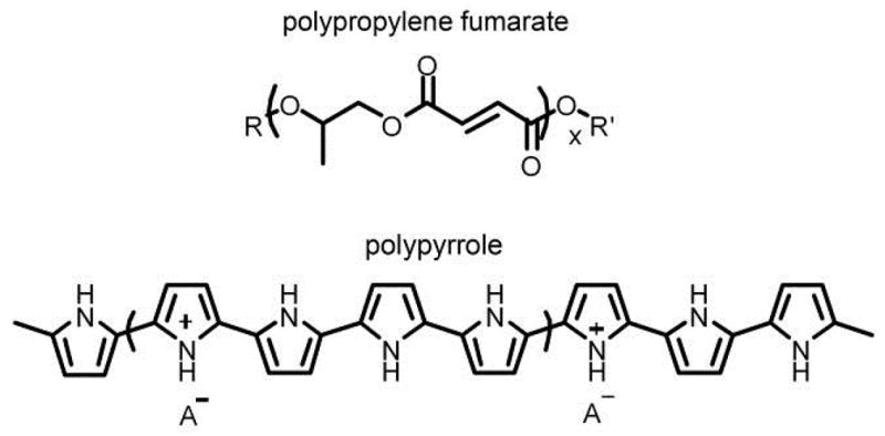
The chemical structures of polypropylene fumarate and polypyrrole.
Figure 2.

Images showing 3-dimensional scaffolds of PPF (left) and after polymerizing pyrrole on the surface of the scaffold resulting in PPF-PPy (right).
ATR-FTIR
ATR-FTIR was used to characterize the presence of PPy on the scaffold surface. Figure 3 shows the appearance of a strong absorption band at 1560 cm−1 for both PPF-PPyNSA and PPF-PPyNSA-HA. This absorption band corresponds to skeletal C-C stretches of the pyrrole ring(13).
Figure 3.

ATR-FTIR of PPF and PPF-PPy scaffolds. The absorbance band at 1560 cm−1 in PPF-PPy scaffolds and not present in the PPF spectrum from pyrrole ring C-C stretches.
XPS
XPS scans of PPF scaffolds show the absence of Ca, P, S, and N. Surface modification treatments successfully incorporated up to 2.3 atomic percent phosphorus and up to 2.5 atomic percent nitrogen which corresponds to approximately 11 percent PPy on the surface of the scaffolds shown in Table 1. PPF-PPyNSA had the lowest resistivity on the order of 2.5 kOhms. PPF-PPyNSA-HA scaffolds had significantly higher resistivity of 2,000 kOhms because the hydroxyapatite anion can displace the naphthalene sulfonic acid that stabilizes polypyrroles positive charge and influences the resulting polymers electrical conductivity.
Table 1.
XPS characterization of PPF scaffolds with conductive and non-conductive coatings.
| XPS Characterization | Resistance (kOhms) | ||||||
|---|---|---|---|---|---|---|---|
| C 1s | Ca 2p | O 1s | P 2p | N | S | ||
| PPF | 63.7 | 0.00 | 36.3 | 0.00 | 0.00 | 0.00 | - |
| PPF-PPyNSA | 71.62 | 0.00 | 28.31 | 0.00 | 0.00 | 0.07 | 2.5 |
| PPF-PPyNSA-HA | 62.71 | 2.19 | 31.12 | 1.32 | 2.48 | 0.18 | 2,000 |
TGA
The scaffold bulk composition was characterized by thermo gravimetric analysis and the results are shown in Figure 4. Polypyrrole degrades to half the original sample weight, and therefore bulk composition could be determined by increases in residual sample weight after heating compared to PPF. TGA shows a 1% increase in residual material after degradation of PPF-PPyNSA that indicates 2% of the scaffold bulk material is PPy.
Figure 4.
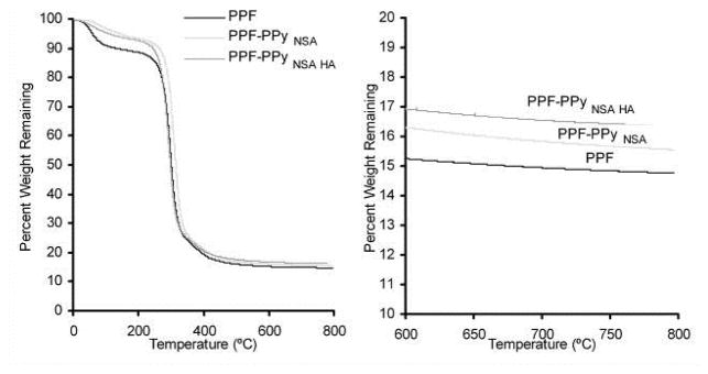
Thermogravimetric analysis (TGA) of PPF and PPF-PPy scaffolds.
Cytotoxicity of leaching materials
Cytotoxicity evaluations of all scaffolds were performed with the human fetal osteoblast (hFOB) cell line. The hFOB cells were plated 24 h before addition of the polymeric materials via suspension of the polymeric material above the cells via transwells. Cells were exposed to leaching materials from the scaffolds without being in direct contact with the polymeric material for 1, 3, and 7 days. Viable cells were quantified with MTS reagents and compared to cells cultured in the absence of the polymeric materials. Figure 5 shows that cell viability decreased at days 1 and 3 in the presence of leaching materials released from PPF scaffolds when the scaffolds were not purified by soxhlet extraction. However, after 7days, cells maintained their viability in the presence of these scaffold. No toxicity was observed when cells were exposed to the leaching materials released from PPF scaffolds after extraction or after coating with PPy at days 1, 3 and 7.
Figure 5.

Cytotoxicity of PPF scaffolds showing the importance of extracting residual starting materials from PPF scaffolds.
Attaching cell viability and morphology
A rotating wall vessel reactor bioreactor with cell suspension was used for cell seeding on 3-dimentional PPF scaffolds (Figure 6). After 16 h in the bioreactor, scaffolds with cells attached were transferred to tissue culture plates for 1, 3, and 7 days. Viability of attaching osteoblasts and their morphology were imaged by fluorescence microscopy after staining with Live/Dead kit and are shown in Figure 7. Microscopy reveals that hFOB cells attached preferentially to PPF-PPyNSA-HA and PPF over PPF-PPyNSA after 16 h in the bioreactor. PPF and PPF-PPyNSA-HA scaffolds were covered in cells at all time points. The cell morphologies were elongated, the typical osteoblast morphology. Initially, cells on PPF-PPyNSA appeared to be round. However, the majority of cells remained viable with a few dead cells on the surface. The red surface observed at Day 3 on the PPF scaffold is believed to be auto fluorescence of the PPF scaffold. Both analyses showed trends favoring attachment and proliferation of hFOB cells on PPFNSA-HA and PPF. SEM also shows a fibroblastic morphology for the osteoblasts attached to the surface of PPF scaffolds coated with PPy (Figure 8). This morphology is typical of differentiating osteoblasts.
Figure 6.

Image of rotary wall vessel bioreactor
Figure 7.

Confocal microscopy images of hFOB cells cultured on PPF scaffolds purified by soxhlet extraction subsequently coated after 1 day (top), 3 days (middle), and 7 days (bottom). All scale bars are 200 μm.
Figure 8.
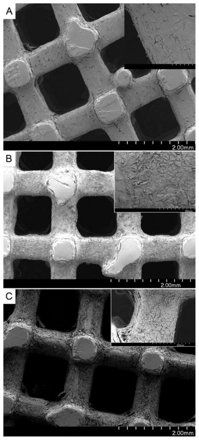
Scanning electron microscopy scaffolds after hFOB cells were cultured for 7 days. Top) PPFPLGA-HA scaffold, upper right corner is blow up of outlined square. A) shows hFOB cells attached to the scaffold B) indicates areas of PLGA-HA coating, and C) shows areas where the PLGA-HA coating has delaminated from the PPF scaffold. Middle) PPF-PPyNSA and bottom, is PPF-PPyNSA-HA.
Cell attachment and proliferation
After seeding the cells in bioreactor, scaffolds were incubated in a static condition in tissue culture plate for 1, 3 and 7 days. Cell attachment and proliferation on different scaffolds are compared in Figure 9. At day 1, initial cell attachment on the PPF scaffolds coated with PPy and PPy-HA were significantly less than that on PPF without the coating (p<0.005). However, cell attachment significantly increased on PPF coated scaffolds at day 3 and 7 (p<0.05). After 7 days, cell number on all scaffolds was greater than those at days 1 and 3 (p<0.05). The number of attached cells on PPF-PPyNSA-HA was significantly higher than that on PPF-PPyNSA at days 3 and 7(p<0.05).
Figure 9.
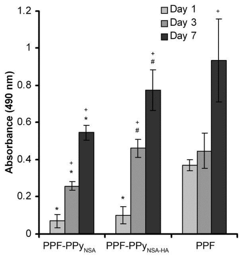
MTS assays of hFOB cells on PPF based scaffolds. Error bars represent standard deviation. *denotes significant differences (p<0.05) between scaffolds compared to PPF. #denotes significant differences (p<0.05) between PCLF-PPy groups at the same time point. +denotes significant differences (p<0.05) compared to day 1 of the same scaffolds.
Alkaline phosphatase activity
ALP activity is characteristic of osteoblast differentiation and is often used as early marker of osteogenesis. An ALP assay was used to determine whether hFOB cells maintain their osteogenic phenotype when cultured on the PPF scaffolds with different surface treatments. Figure 10 shows that ALP activity of hFOB cells increased on all scaffolds at day 3 and then decreased by day 7. ALP activity of osteoblasts on PPF scaffolds coated with PPy-HA was significantly higher than that at days 1 and 7 (p<0.0003). In addition, ALP activity of hFOB cells on these scaffolds at day 3 was significantly higher than that on PPF-PPy scaffolds without HA (p<0.05). At day 7, ALP activity was similar on all scaffolds.
Figure 10.

Alkaline phosphatase activity of hFOB cells on different scaffolds at 1, 3 & 7 days. # denotes significant differences (p<0.05) between PPF-PPy groups at the same time point. *denotes significant differences within groups between days compared to day 1.
DISCUSSION
Porous three-dimensional PPF scaffolds with 1000 μm pore size and 500 μm walls were fabricated by UV laser stereolithography. Channels were orthogonal running in vertical and horizontal directions. In order to increase cellular attachment to scaffolds intended for orthopedic applications, it is common for hydroxyapatite or β-tricalcium phosphate to be incorporated into the scaffolds(14). However, requirements of the stereolithography resin often limits the modifications to the resin that may increase the cellular compatibility of the resulting scaffold. An example is the incorporation of hydroxyapatite which is used to promote attachment of osteoblasts and bone regeneration. Hydroxyapatite is an insoluble particle that when mixed with PPF resins rapidly settles out. Therefore surface modification by coating PPF scaffolds is necessary when using UV stereolithography.
The use of electrical stimulation to increase the successful healing rate of nonunions, delayed unions and fracture healing is promising therapy for promoting bone regeneration(7). Initial report shows that direct stimulation of fracture sites is effective treatments in promoting fusion of difficult cases in combination with bone grafts(15–19). Polymeric scaffolds such as PPF can potentially replace bone grafts often used for large bone defects. By further extending these scaffolds to be electrically conductive for potential treatments involving electrical stimulation may increase the scaffold osteoconductivity. This initial work evaluates the effect of electrically conductive coatings using polypyrrole, and polypyrrole containing hydroxyapatite on osteoblast behavior. The electrically conductive PPy coating was chosen because of its well know biocompatibility, and high electrical conductivity, and environmental stability. A solution deposition method was used for polymerizing pyrrole on the PPF scaffolds because it allows a homogenous coating of the polymer onto the three dimensional scaffold. Hydroxyapatite a commonly used calcium phosphate for orthopedic applications was chosen to evaluate the effect of its inclusion in the PPy on the scaffold electrical conductivity and biocompatibility.
PPF scaffolds were successfully coated with PPy. The homogenous PPy coatings were electrically conductive. The differences in resistivity between PPF-PPyNSA (2.5 kΩ) and PPF-PPyNSA-HA (2,000 kΩ) can be attributed to the incorporation of the hydroxyapatite. Because hydroxyapatite is a calcium phosphate anion, it can potentially displace the naphthalene sulfonic acid anion that typically stabilizes polypyrrole positive charge and influences the resulting polymers electrical conductivity. The XPS data show that there is significantly more phosphate than sulfur in PPF-PPyNSA-HA, indicating that the anion interacting with PPy is mainly from the calcium phosphate. This agrees with previous reports that have shown calcium phosphates can be co-precipitated with PPy on the surface of titanium implants (20, 21). XPS also show that surface modification treatments successfully incorporated up to 2.3 atomic percent phosphorus and up to 2.5 atomic percent nitrogen onto the scaffold surface. This corresponds to approximately 11 percent PPy on the surface of the scaffolds. Data from TGA demonstrate that polypyrrole degrades to half the original sample weight, and the increase in residual sample weight was used to determine bulk composition. TGA shows a 1% increase in residual material after thermal degradation PPF-PPyNSA indicating 2% PPy by weight was incorporated into the bulk material. This low percentage of polypyrrole incorporated into the bulk material will help maintain the overall biodegradability of the final scaffold. For PPF-PPyNSA-HA 2% residual material remains. The additional 1% is from the incorporation of hydroxyapatite on to the scaffold surface.
Cytotoxicity from leaching materials was observed for PPF materials at days 1 and 3 when the scaffolds were not purified by soxhlet extraction. The cause of toxicity was shown to be the residual diethyl fumarate leaching from the cross-linked scaffolds. Diethyl fumarate is used as a comonomer and solvent to give PPF the required viscosity and cross-linking properties for use in the Viper UV stereolithography machine(5). Removal of residual diethyl fumarate from the scaffolds was performed by soxhlet extraction using THF. This step is the key to removing unreacted materials from the PPF based scaffolds. THF was used because it does not destroy the scaffold, and can be removed by extensive dialysis in water before use or further surface modification. The highly porous, three dimensional scaffolds were seeded using a rotating wall vessel reactor to keep the hFOB cells suspended in cell media allowing ample time for cell attachment to the scaffolds. Microscopy shows that hFOB cells preferentially attach to the PPF and PPF-PPyNSA-HA scaffolds over PPF-PPyNSA. The cells exhibit an elongated morphology on PPF and PPF-PPyNSA-HA. Some of the cells on PPF-PPyNSA appear round, but they are stained green indicating their viability. Dead cells also appear on the scaffold surface indicating a less favorable cell-scaffold interaction for PPF-PPyNSA. The MTS assays corroborate the images of PPF but conflict with the microscopy image PPF-PPyNSA-HA. This disagreement is attributed to the interaction of the MTS reagent with PPy. At day 1 the MTS assay was performed without trypsinizing the cells from the scaffolds, and therefore reagent was in direct contact with the scaffolds. It is likely that the reagent was absorbed onto the scaffold surface, effectively removing it from the media resulting in artificially low readings. At days 3 and 7, the cells were trypsinized from the scaffold before the MTS assay and the results were in better agreement with the microscopy images. Cells proliferated well over the course of 7 days cells on all scaffolds, however the large differences in cell numbers after the initial cell attachment was insurmountable between groups. Both analyses showed trend favoring attachment and proliferation of hFOB cells on PPFNSA-HA and PPF. It appears that incorporation of the HA in PPF coating makes significant difference in cell proliferation. We also demonstrated that hFOB cells maintained their osteogenic phenotype and expressed ALP activity in all time points on scaffolds.
CONCLUSIONS
We demonstrated that PPy was successfully coated on the surface PPF scaffolds fabricated by rapid prototyping, and the polypyrrole coated scaffolds exhibited electrical conductivity. There was no cytotoxicity of residual materials after further extraction of scaffolds. Incorporation of HA into the PPy coating improved cell attachment and proliferation of osteoblasts onto the PPF scaffolds. Osteoblasts maintained their phenotype on all PPF scaffolds. Thus, these scaffolds could be appropriate candidate for our future in vivo studies.
Acknowledgments
This work was funded by NIH training grant 1T32AR056950-01, the NIH Loan Repayment Program, NIBIB PAR56212, NIAMS R01 AR056212, and the Armed Forces Institute of Regenerative Medicine by DOD activity contract # W81XWH-08-2-0034.
References
- 1.Yan J, Li J, Runge MB, Dadsetan M, Chen Q, Lu L, Yaszemski MJ. Cross-linking characteristics and mechanical properties of an injectable biomaterial composed of polypropylene fumarate and polycaprolactone co-polymer. J Biomater Sci Polym Ed. 2011;22:489–504. doi: 10.1163/092050610X487765. [DOI] [PMC free article] [PubMed] [Google Scholar]
- 2.Wang K, Cai L, Hao F, Xu X, Cui M, Wang S. Distinct cell responses to substrates consisting of Poly(Iμ-caprolactone) and poly(propylene fumarate) in the presence or absence of cross-links. Biomacromolecules. 2010;11:2748–59. doi: 10.1021/bm1008102. [DOI] [PubMed] [Google Scholar]
- 3.Chang CH, Liao TC, Hsu YM, Fang HW, Chen CC, Lin FH. A poly(propylene fumarate) - Calcium phosphate based angiogenic injectable bone cement for femoral head osteonecrosis. Biomaterials. 2010;31:4048–55. doi: 10.1016/j.biomaterials.2010.01.124. [DOI] [PubMed] [Google Scholar]
- 4.Lee KW, Wang S, Dadsetan M, Yaszemski MJ, Lu L. Enhanced cell ingrowth and proliferation through three-dimensional nanocomposite scaffolds with controlled pore structures. Biomacromolecules. 2010;11:682–89. doi: 10.1021/bm901260y. [DOI] [PMC free article] [PubMed] [Google Scholar]
- 5.Lee K, Wang S, Fox B, Ritman E, Yaszemski M, Lu L. Poly(propylene fumarate) bone tissue engineering scaffold fabrication using stereolithography: Effects of resin formulations and laser parameters. Biomacromolecules. 2007;8:1077–84. doi: 10.1021/bm060834v. [DOI] [PubMed] [Google Scholar]
- 6.Lemons JE. Hydroxyapatite coatings. Clin Orthop Relat Res. 1988:220–3. [PubMed] [Google Scholar]
- 7.Goldstein C, Sprague S, Petrisor BA. Electrical stimulation for fracture healing: current evidence. J Orthop Trauma. 2010;24 (Suppl 1):S62–5. doi: 10.1097/BOT.0b013e3181cdde1b. [DOI] [PubMed] [Google Scholar]
- 8.Wang S, Lu L, Yaszemski MJ. Biomacromolecules. 2006;7:1976–82. doi: 10.1021/bm060096a. [DOI] [PMC free article] [PubMed] [Google Scholar]
- 9.Wang S, Kempen DH, Simha NK, Lewis JL, Windebank AJ, Yaszemski MJ, Lu L. Biomacromolecules. 2008;9:1229–41. doi: 10.1021/bm7012313. [DOI] [PMC free article] [PubMed] [Google Scholar]
- 10.Lee KW, Wang S, Yaszemski MJ, Lu L. Biomaterials. 2008;29:2839–48. doi: 10.1016/j.biomaterials.2008.03.030. [DOI] [PMC free article] [PubMed] [Google Scholar]
- 11.Baltrusaitis J, Usher CR, Grassian V. Reactions of sulfur dioxide on calcium carbonate single crystal and particle surfaces at the adsorbed water carbonate interface. Phys Chem Chem Phys. 2007;9:3011–24. doi: 10.1039/b617697f. [DOI] [PubMed] [Google Scholar]
- 12.Fairley, N., 2.3.14., C. V. 1999–2008.
- 13.Runge MB, Dadsetan M, Baltrusaitis J, Knight A, Ruesink T, Lazcano E, Lu L, Windebank AJ, Yaszemski MJ. The Development of Electrically Conductive Polycaprolactone Fumarate-Polypyrrole Composite Materials for Nerve Regeneration. Biomaterials. 2010;31:5916–26. doi: 10.1016/j.biomaterials.2010.04.012. [DOI] [PMC free article] [PubMed] [Google Scholar]
- 14.de Jonge LT, Leeuwenburgh SC, Wolke JG, Jansen JA. Organic-inorganic surface modifications for titanium implant surfaces. Pharm Res. 2008;25:2357–69. doi: 10.1007/s11095-008-9617-0. [DOI] [PubMed] [Google Scholar]
- 15.Dodge GR, Bowen JR, Jeong C. Vertebral growth modulation by electrical current in an animal model: potential treatment for scoliosis. J Pediatr Orthop. 30:365–70. doi: 10.1097/BPO.0b013e3181d8fa74. [DOI] [PMC free article] [PubMed] [Google Scholar]
- 16.Hughes MS, Anglen JO. The Use of Implantable Bone Stimulators in Nonunion Treatment. Orthopedics. :151–57. doi: 10.3928/01477447-20100129-15. [DOI] [PubMed] [Google Scholar]
- 17.Lau JT, Stamatis ED, Myerson MS, Schon LC. Implantable direct-current bone stimulators in high-risk and revision foot and ankle surgery: a retrospective analysis with outcome assessment. Am J Orthop (Belle Mead NJ) 2007;36:354–7. [PubMed] [Google Scholar]
- 18.Fredericks DC, Smucker J, Petersen EB, Bobst JA, Gan JC, Simon BJ, Glazer P. Effects of direct current electrical stimulation on gene expression of osteopromotive factors in a posterolateral spinal fusion model. Spine (Phila Pa 1976) 2007;32:174–81. doi: 10.1097/01.brs.0000251363.77027.49. [DOI] [PubMed] [Google Scholar]
- 19.Toth JM, Seim HB, 3rd, Schwardt JD, Humphrey WB, Wallskog JA, Turner AS. Direct current electrical stimulation increases the fusion rate of spinal fusion cages. Spine (Phila Pa 1976) 2000;25:2580–7. doi: 10.1097/00007632-200010150-00007. [DOI] [PubMed] [Google Scholar]
- 20.Li M, Qu L, Ma C, Yang S. Bioactive and stability of calcium phosphate- polypyrrole composite coatings by electrochemical deposition. PART 2. 2008. pp. 368–372.pp. 1198–200. [Google Scholar]
- 21.Ma C, Qu L, Li M, Yang S, Wang J. Electrochemically assisted co-precipitation of electrically conducting polymer with calcium phosphate coatings on Ti alloys. II. 2007. pp. 336–338.pp. 1632–34. [Google Scholar]