Abstract
Introduction
Facial transplantation represents one of the most complicated scenarios in craniofacial surgery because of skeletal, aesthetic, and dental discrepancies between donor and recipient. However, standard off-the-shelf vendor computer-assisted surgery systems may not provide custom features to mitigate the increased complexity of this particular procedure. We propose to develop a computer-assisted surgery solution customized for preoperative planning, intraoperative navigation including cutting guides, and dynamic, instantaneous feedback of cephalometric measurements/angles as needed for facial transplantation.
Methods
We developed the Computer-Assisted Planning and Execution (CAPE) workstation to assist with planning and execution of facial transplantation. Preoperative maxillofacial computed tomography (CT) scans were obtained on 4 size-mismatched miniature swine encompassing 2 live face-jaw-teeth transplants. The system was tested in a laboratory setting using plastic models of mismatched swine, after which the system was used in 2 live swine transplants. Postoperative CT imaging was obtained and compared with the preoperative plan and intraoperative measures from the CAPE workstation for both transplants.
Results
Plastic model tests familiarized the team with the CAPE workstation and identified several defects in the workflow. Live swine surgeries demonstrated utility of the CAPE system in the operating room, showing submillimeter registration error of 0.6 ± 0.24 mm and promising qualitative comparisons between intraoperative data and postoperative CT imaging.
Conclusions
The initial development of the CAPE workstation demonstrated integration of computer planning and intraoperative navigation for facial transplantation are possible with submillimeter accuracy. This approach can potentially improve preoperative planning, allowing ideal donor-recipient matching despite significant size mismatch, and accurate surgical execution.
Keywords: Computer-assisted planning, computer-integrated surgery, cutting guides, maxillofacial transplant, swine facial transplant, craniofacial, craniomaxillofacial surgery, swine study, face transplant
Facial transplantation is an emerging therapeutic option for patients with complex craniomaxillofacial defects. To date, nearly 25 facial transplants have been reported, with approximately one-third containing underlying facial skeleton and jaw components.1–3 Operative times for these complex, Le Fort–based facial transplantations can exceed 30 hours.4–6 However, each previous maxillofacial single-jaw recipient has developed some type of postoperative deformity due to size mismatch and malocclusion between donor and recipient, ultimately requiring revisional surgery.7 In addition, there are currently no validated methods for optimizing outcomes related to facial (soft tissue), skeletal (hard tissue), and occlusal (dental) inconsistencies in the setting of donor-to-recipient anthropometric mismatch—a major hurdle to achieving this specialty’s full potential.8,9
Use of computer technology to improve accuracy and precision of craniofacial surgical procedures has been described for nearly 30 years, since the increasing availability of computed tomography (CT) prompted Cutting et al10 to develop a CT-based surgical simulation plan for osteotomies. Since that time, 2 broad approaches to computer-assisted surgery (CAS) have gained popularity: (1) preoperative surgical planning and the use of three-dimensional printed stereolithography templates (three-dimensional computer-aided design/manufacturing) to guide surgical maneuvers11–13 and (2) utilizing intraoperative feedback relative to preoperative imaging for the surgeon to provide more objective data on what is happening beyond the “eyeball test.”14,15 Much previous work has described the utility and accuracy of such computer-aided design/manufacturing.9,11,13,16 However, none are meant for real-time placement feedback in areas where guide placement is more challenging, such as the three-dimensional facial skeleton. To our knowledge, no existing CAS systems are fully satisfactory for the most complicated craniofacial surgeries such as Le Fort–based, face-jaw-teeth transplantation.
Recently, Brown et al17 described a system including preoperative planning and cutting guides by way of stereolithographic models for human facial transplantation. However, their system (using standard off-the-shelf vendor systems) does not include necessary features to mitigate the increased complexity of this particular procedure. Additional features of interest include (1) intraoperative plan updates based on hard tissue discrepancies between planned and executed procedure, (2) on-table feedback in the form of dynamic cephalometrics, and (3) predesigned fixation plates matching the virtual plan. Furthermore, in the current CAS paradigms for craniofacial surgery, there is little capacity for intraoperative plan updates. This feature becomes especially important because in some circumstances during the transplantation surgery it may be necessary to revise and update the preoperative plans intraoperatively. The CAS system, therefore, must be robust to deal with situations in which tools and templates designed and fabricated preoperatively may not entirely address intraoperative surgical needs. Robustness of the planning and navigation strategy is especially important in total face transplantation given the long operating times.
Better utilization of advanced surgical technology has potential to improve outcomes and decrease accompanying morbidity via shortened operative times, more precise surgical maneuvers, and improved margin of safety. Thus, we developed a CAPE (Computer-Assisted Planning and Execution) system for complex craniofacial surgery such as Le Fort–based, face-jaw-teeth transplantation.18 This CAPE suite addresses common shortcomings of existing CAS systems as stated in the previous paragraph and has the potential to improve outcomes across both the pediatric and adult-based patient population. The following section describes an overview of the CAPE system and its novel features. The results section reports experiments with the CAPE system on plastic bones and 2 live swine surgeries. It is notable that in a previous work we have performed cadaver studies to evaluate anatomical discrepancies and analogous cephalometric points between swine and human for the purpose of translational investigation.18
MATERIALS AND METHODS
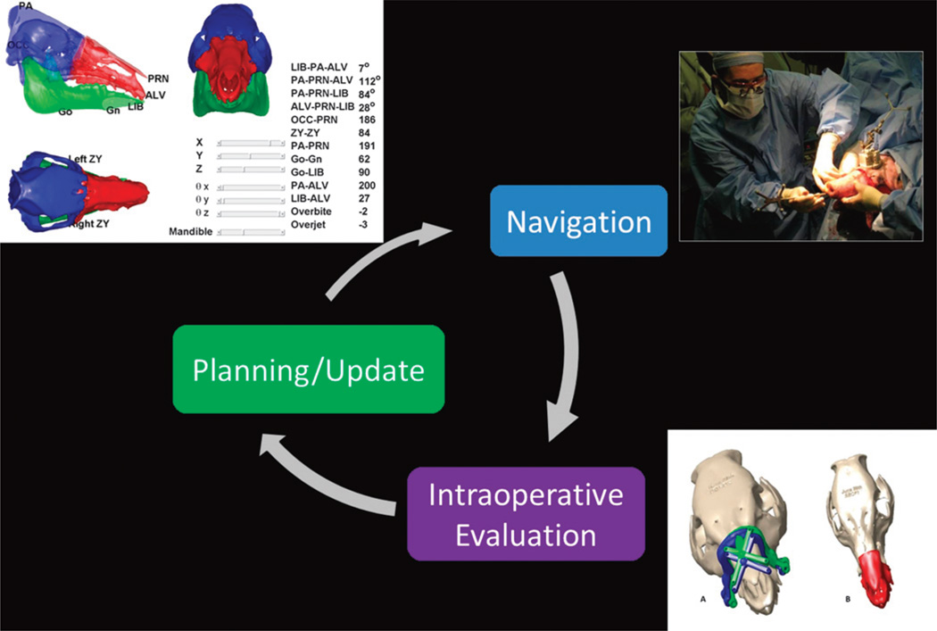
The fundamental paradigm for CAS involves developing a surgical plan, registering the plan and instruments with respect to the patient, and carrying out the procedure according to the plan. This paradigm has been reviewed by many for a variety of different surgical procedures.19–27 In the following, we describe the specific features of the CAPE workstation modules within the CAS paradigm. The CAPE system seeks to increase the robustness of the conventional CAS paradigm by enabling intraoperative evaluation of the surgical plan and providing means for intraoperative plan updates/revisions when needed (Fig. 1).
FIGURE 1.
Computer-Assisted Planning and Execution improves CAS robustness by closing the loop between planning and navigation and enabling intraoperative updates to the plan.
System Overview
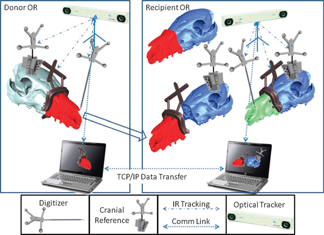
The CAPE system includes integrated planning and navigation modules. The main components of the system are the following: (1) 2 networked workstations concurrently used in planning and navigation of the surgery for both donor and recipient; (2) 2 optical trackers (Polaris, NDI Inc) tracking bone fragments, tools, and soft tissues (not fully implemented yet); (3) novel guides, reference kinematic markers, and so on, as required for navigation (Fig. 2). Preoperative planning involves the following tasks:
segmentation and volumetric reconstruction of the donor and recipient facial anatomy
planning for patient-specific cutting guide placement
cephalometric analysis of the hybrid skeleton
fabrication of the hybrid cutting guides enabling both geometric (“snap-on” fit) and optical navigation
mapping the vascular system on both recipient and donor facial anatomy (not completely implemented yet)
plan updates, if necessary, based on the feedback from the intraoperative module
FIGURE 2.
The schematic overview of the CAPE and its components.
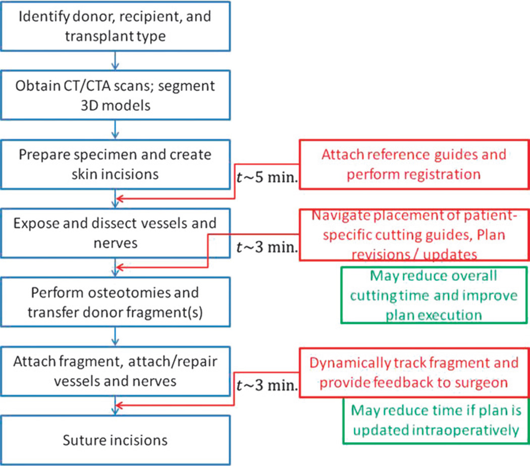
The intraoperative navigation module changes the conventional procedure as shown in Figure 3. The intraoperative tasks for CAPE include (1) registration of the preoperative model reconstructed from the CT data to donor and recipient anatomy; (2) visualization (using information from the optical tracker) of the instruments and cutting guides to help the surgeon navigate; (3) verifying the placement of cutting guides and performing real-time cephalometric and occlusion analysis, if, for any reason, the osteotomy sites need to be revised; (4) dynamically tracking the attachment of the donor fragment to the recipient and providing quantitative and qualitative (visual) feedback to the surgeon.
FIGURE 3.
The additional procedures associated with the use of the CAPE system (shown in red) and the approximate time taken for each procedure.
Preoperative Planning
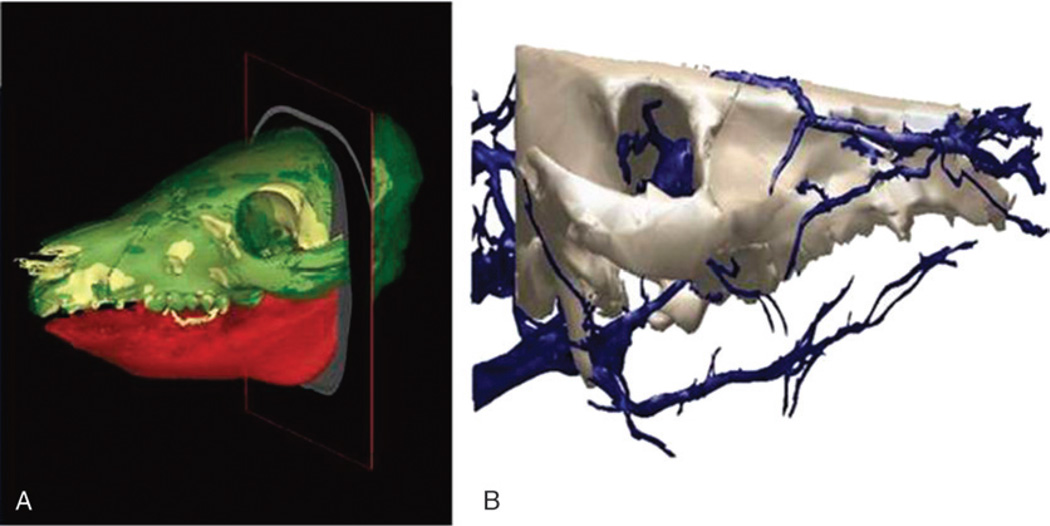
During the initial planning stage, surgeons determine a virtual plan based on the recipient’s craniofacial deformity irrespective of the donor. From registered CT data, segmentation software generates volume data for specific key elements (eg, the mandible, maxilla, and cranium) used for preoperative planning and visualization. The planning workstation automatically generates the expected cut geometry of the donor fragment together with the recipient, thereby defining the predicted facial skeleton with accompanying hybrid occlusion2,3,8,18,28 (Fig. 4A). If available, blood vessels are segmented from CT angiography scans (Fig. 4B).
FIGURE 4.
A, Computed tomography scan reconstructed images of size-mismatched facial skeleton generated from segmentation software utilized for preoperative planning. B, Segmented arterial system of craniomaxillofacial skeleton generated from CT angiography (CTA) data.
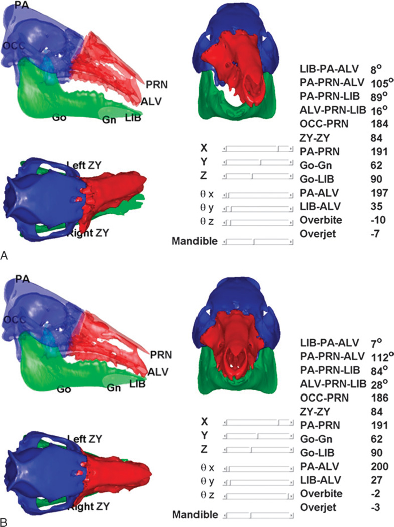
The planning module also performs static cephalometric analysis and evaluation of face-jaw-teeth harmony on varying constructions of the hybrid donor and recipient jaw (Fig. 5). Using this tool, the surgeon can evaluate different placements for the donor’s face-jaw-teeth alloflap on the recipient’s face in relation to orbital volumes, airway patency, facial projection, and dental alignment. The automated cephalometric computation for the hybrid face indicates the validity of the planned surgery from both an aesthetic and reconstructive standpoint8,28 (Table 1). To evaluate and predict cephalometric relationships both during planning and intraoperative environments, the system uses validated, translational landmarks between swine and human.9,18 The cephalometric parameters defined by these landmarks are automatically recalculated as the surgeon relocates the bone fragments using CAPE’s graphical user interface (Fig. 5).
FIGURE 5.
On-screen images from CAPE system displaying real-time, dynamic cephalometrics and pertinent measurements applicable to humans. Panel A shows donor’s face-jaw-teeth alloflap in suboptimal position as compared with recipient’s cranium (black arrow). Panel B shows appropriate face-jaw-teeth positioning with immediate surgeon feedback and updated cephalometric data pertinent to preclinical investigation.
TABLE 1.
Pertinent Landmarks for Cephalometric Analysis and Cephalometric Measurements and Related Units
| Symbol | Name and Definition | ||||||||||||
|---|---|---|---|---|---|---|---|---|---|---|---|---|---|
| Go | Gonion: a point midway between points defining angles of the mandible | ||||||||||||
| Gn | Gnathion: most convex point located at the symphysis of the mandible | ||||||||||||
| ALV | Alveolare: midline of alveolar process of the upper jaw, at incisor-alveolar junction | ||||||||||||
| LIB | Lower incisor base: midline of anterior border of alveolar process of mandible at the incisor-alveolar junction | ||||||||||||
| PA | Parietale: most superior aspect of skull in the midline, (formed by nuchal crest of occipital bone and parietal bone) | ||||||||||||
| PRN | Pronasale: bony landmark representing anterior limit of nasal bone | ||||||||||||
| ZY | Zygion: most lateral point of malar bone | ||||||||||||
| OCC | Occipital region: midpoint between the occipital condyles | ||||||||||||
| B. Cephalometric Measurements and Related Units | |||||||||||||
| Measure | ZY-ZY | PA-PRN | Go-Gn | Go-LIB | PA-ALV | LIB-ALV | Overbite | Overjet | OCC-PRN | LIB-PA-ALV | PA-PRN-ALV | PA-PRN-LIB | ALV-PRN-LIB |
| Units | mm | mm | mm | Mm | mm | mm | mm | mm | mm | degrees | degrees | degrees | degrees |
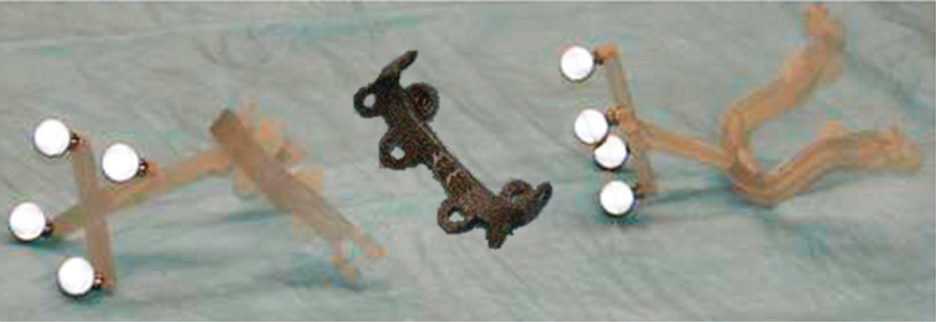
Preoperative planning also involves fabrication of the custom guides and palatal splints. The planned cut planes form the basis for the patient-specific cutting guides, designed with a “snap-on” fit to both donor and recipient. A reference geometry built into the guide structure enables dynamic intraoperative tracking of guides with respect to the patient’s skeleton. Palatal splints ensure planned dentoskeletal alignment fixation following Le Fort–type facial transplants. Fixation plates possess eyelets for screw placement to provide rigid immobilization at the irregular skeletal contour areas along various donor-to-recipient interfaces. Having prebent fixation plates decreases total operative times and helps to confirm accurate skeletal alignment (Fig. 6).
FIGURE 6.
Photograph of prebent fixation plates with screw holes and navigational cutting guides provided by the CAPE system for live swine surgery.
Intraoperative Surgical Assistance
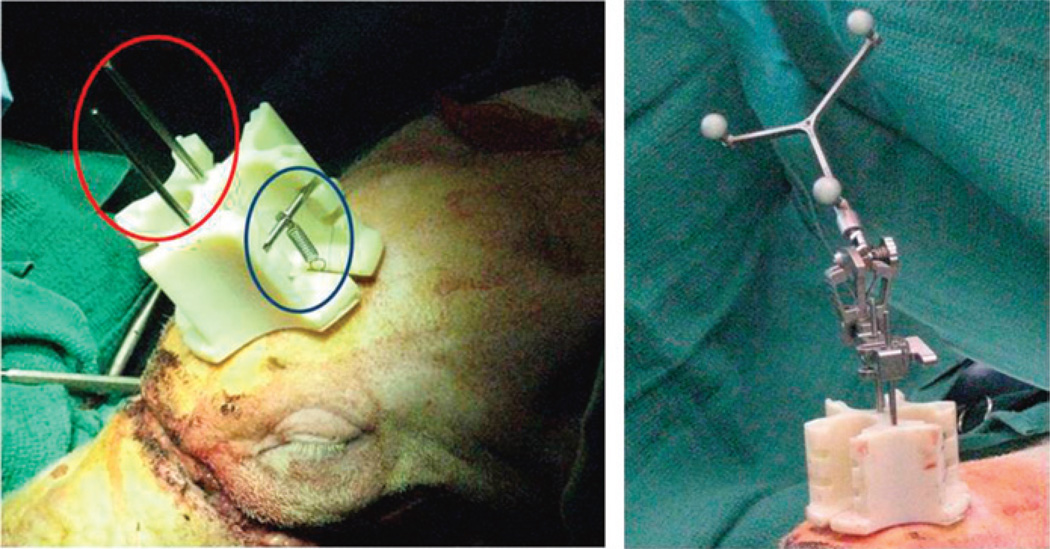
Individual navigation for both donor and recipient surgeries tracks the cutting guides with respect to planned positions. Surgeons attach a novel kinematic reference mount to 3 intramedullary fixation (IMF) screws arranged in a triangular pattern on each the donor and recipient craniums (Fig. 7). The mount design permits flexibility in the placement of the IMF screws so that no template is necessary. A spring attaches to each IMF screw via suture threaded through the eyelets. These springs hold the cranial mount in place and allow easy removal and replacement of the cranial mount (eg, during positional changes required for bone cuts and soft tissue dissections). The key design advantages of the reference are detachability and use of IMF screws for stable attachment.
FIGURE 7.
A novel kinematic reference mount (red circle) being fixated to donor’s cranium with intermaxillary screws. Permanent suture attaches 3 necessary springs and cross bars for stabilization (blue circle) allowing easy removal and replacement during surgery. The photograph on the right shows an “off-the-shelve” detachable rigid body (Brainlab) with reflective markers attached to the reference body.
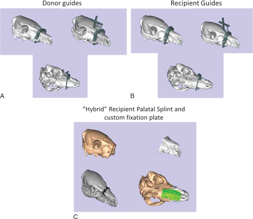
The reference geometry (Brainlab, Westchester, IL) attached to the kinematic mount provides a static coordinate frame attached to the patient. The surgeon digitizes 3 bony landmarks (eg, the inferior aspect of the orbits and anterosuperior maxilla) to define a rough registration between the environment and virtual models. The surgeon collects several point sets from exposed bone using the digitization tool and uses an iterative closest point registration technique to refine the registration.29 Once registered, the surgeon navigates the placement of the cutting guide using the combination of “snap-on” geometric design and the tracking system coupled to visual feedback (Fig. 8). This allows the team to assess inaccuracies related to soft tissue interference, iatrogenic malpositioning, anatomical changes since acquiring original CT scan data, and/or imperfections in cutting guide design or three-dimensional printing process.
FIGURE 8.
Illustrations show novel cutting guide designs with navigational capabilities designed for donor face-jaw-teeth alloflap recovery (A), recipient preparation prior to transplant (B), and custom prebent fixation plate (black) and palatal splint (green) designed to achieve planned face-jaw-teeth alignment and skeletal inset with standard technique (C).
Self-drilling screws affix the cutting guide to the patient’s skeleton to ensure osteotomies are performed along predefined planes, maximizing bony congruity. After dissecting the donor’s maxillofacial fragment and preparing the recipient’s anatomy, the surgical team transfers the facial alloflap. The CAPE workstation tracks the final three-dimensional placement of the Le Fort–based alloflap providing real-time visualization (Fig. 5). This provides real-time visualization of important structures,7,8 such as new orbital volumes (vertical limit of inset), airway patency (posterior horizontal limit of inset), and facial projection (anterior horizontal limit of inset). Once confirmed, the surgeon fixates the donor alloflap to the recipient following conventional techniques.
Development of this technology encompassed 2 separate phases. Phase 1 utilized swine molds and swine cadaver heads for surgical practice. The second phase used 2 live translational surgeries performed on 4 miniature swine (n = 2 transplants) for preclinical experimentation.9,18
RESULTS
Overall, several plastic model tests and 2 swine cadaver surgeries helped to familiarize the surgical team in a low-cost and less stressful fashion. Within this phase, team members learned optimal sequences to interact with the intraoperative navigation and repeated various steps for tracking point capture. These iterations resulted in design alterations of the cutting guides to reduce flex and bending for more precise tracking. The novel design (Fig. 8) helped to improve the tracking accuracy from millimeter to submillimeter levels.
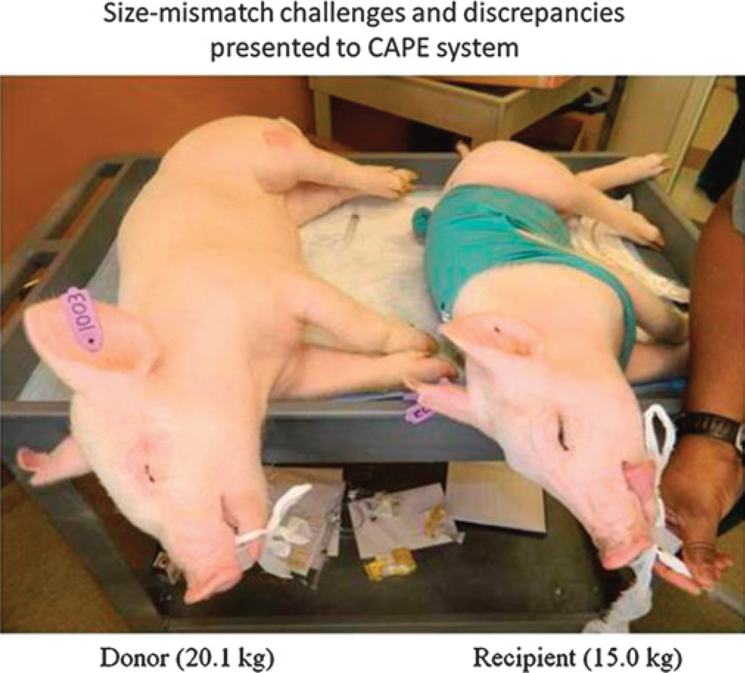
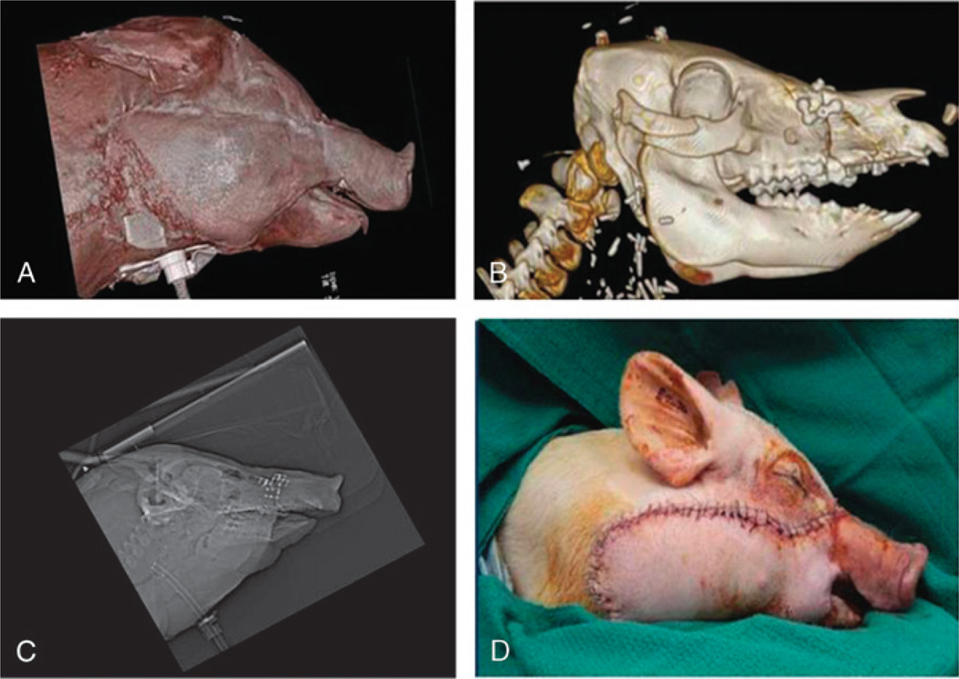
Live transplant surgeries (n = 2) between 4 size-mismatched swine (Fig. 9) investigated whether the CAPE suite could actually assist the surgical team in planning and in executing the desired surgical plan. The first live surgery confirmed the proposed utility of overcoming soft and hard tissue discrepancies related to function and aesthetics7,8 (Figs. 10A, B). The final occlusal plane within the first recipient was ideal and consistent with the virtual plan as seen on lateral cephalogram (Fig. 10C). Preoperative functional predictions of donor-to-recipient occlusion were realized based on cephalometric analyses performed both before and after surgery. The soft tissue inconsistencies of the larger-to-smaller swine scenario were also reduced following the predicted movements of face, jaw, and teeth (Fig. 10D).
FIGURE 9.
Size-mismatched swine are used for preclinical investigation simulating size discrepancies common to human maxillofacial transplantation. In addition, transplant studies in swine (versus single animal studies) provide our team the most severe challenges related to anatomical discrepancies important for technology development.
FIGURE 10.
Large size-mismatch maxillofacial transplant: (A) profile view of CT scan depicts appropriate soft tissue aesthetic harmony; (B) CT scan depicts skeletal alignment and “hybrid” occlusion; (C) lateral cephalogram depicts acceptable cephalometrics; (D) live recipient following face-jaw-teeth transplant.
The second live surgery showed improved success as compared with its predecessor because of surgeon familiarity and technology modifications. The CAPE system improvements and growing comfort of the surgeons led to reduced operative times for both donor and recipient surgeries. Overall, the surgical time reduced from more than 14 hours to less than 8 hours because of improved surgical workflow (outside CAPE) and increased comfort with CAPE.
Based on the results obtained in the live and plastic bone surgeries (Fig. 2), the functions associated with setting up the CAPE system (attaching references, performing registration, attaching cutting guides) add about 11 minutes to the total length of surgery. However, the overall time can be reduced by minimizing the time required for tracking, locating, and reaching areas of interest during the operation. The overall time for surgery can especially be reduced if information regarding the mapping of vasculature and nerves is presented to the surgeon intraoperatively.
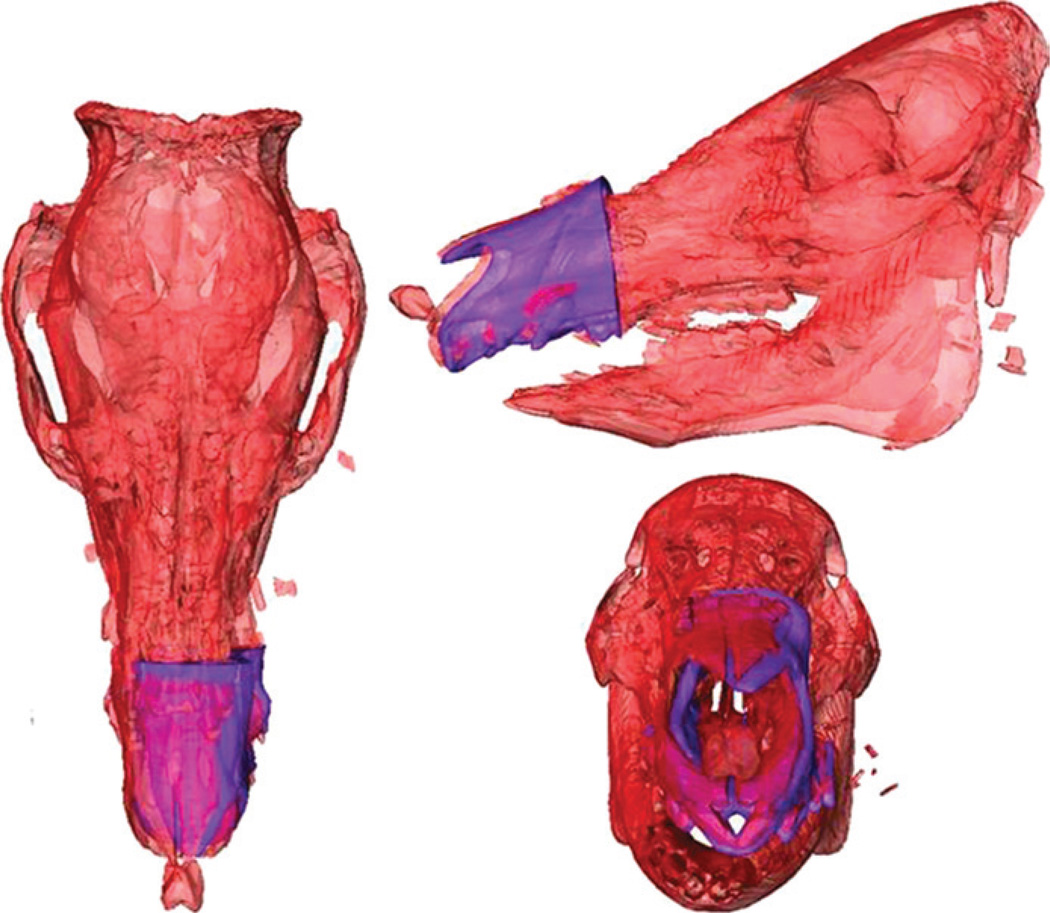
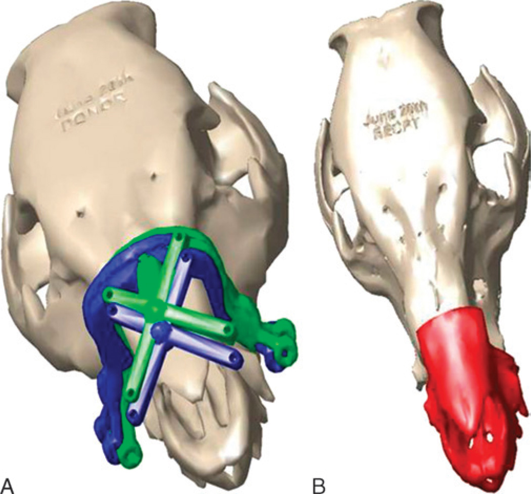
The information recorded from the CAPE suite relating the donor fragment to the recipient qualitatively matched the postoperative CT data (Fig. 11). The recipient cutting guide was not placed as planned, however, because of an unexpected collision between cranial reference mount and recipient cutting guide (Fig. 12). In this case, there was anterior translation of the cutting guide (toward the tip of the swine’s snout) by approximately 4 cm.
FIGURE 11.
Computer-Assisted Planning and Execution system images of transplant recipient skeleton (red) in bird’s eye view (A), left-sided profile view (B), and frontal view (C) depicting real-time assessment of planned (pink) versus actual face-jaw-teeth position (purple).
FIGURE 12.
“On-screen” image from CAPE system depicting ideal location of cutting guide (green) versus actual position (red) (A) and actual inset position of donor alloflap (red) for aesthetic, dental, and skeletal relation in size-mismatched swine because of anterior translation of cutting guide (B).
Overall, the donor and recipient craniums (n = 4) were registered successfully to the reference bodies for both live surgeries. The model to patient registration error across the surgeries was 0.6 (SD, 0.24) mm. The novel cutting guide designs proved highly useful in carrying out the planned bone cuts, which compensated for size-mismatch discrepancies between donor and recipient. Marking spheres fixated to the guides allowed real-time movement tracking and “on-table” alloflap superimposition onto the recipient, thereby allowing visualization of the final transplant result.
DISCUSSION
We developed and demonstrated a single-platform solution, the CAPE workstation, for performing facial transplantation and similar craniomaxillofacial surgical procedures. It provides a preoperative module to define bone cuts on donor and recipient bonemodels for virtual planning, provides patient-specific three-dimensional designs for cutting guide fabrication/tracking, and tracks the cutting guides and bone fragments during surgery. These benefits provide instantaneous surgeon feedback and the ability to intraoperatively update plans without discarding the CAS system, if surgical plans need modification.
Compared with previous efforts, this system extends the advantages of CAS beyond that described by Dorafshar et al.6 This group described using off-the-shelf vendors for navigation and using stereolithographic modeling for osteotomy guidance during double-jaw face transplantation. Although similar, a double-jaw transplant, as reported, is unlike a single-jaw maxillofacial transplant in that it accompanies no concerns for face-jaw-teeth inconsistencies between donor and recipient because the transplanted teeth-bearing jaws are from the same individual. We present here a new platform for preoperative planning and intraoperative predictions related to soft tissue–skeletal–dental alignment with real-time tracking of cutting guides for 2 mismatched jaws of varying width, height, and projection. Additional safeguards, such as collection of confidence points as described below, further enable intraoperative verification of the system accuracy. This, in addition to performing real-time plan verification via tracking and dynamic cephalometry, will considerably increase the robustness of the system (Fig. 1). Moreover, the modular nature of the CAPE system allows additional functionality to be continually added.
Plastic bone studies identified areas of improvement and familiarized surgeons with workflow and helped us to identify difficulties. The 2 live swine surgeries tested the system in a true surgical environment and confirmed its efficacy.18 The outcomes of these surgeries identified the utility of cutting guides coupled with navigation and patient-specific fixation (eg, the palatal splint), and the navigation system is still able to obtain real-time information in the event the guides cannot be placed as planned.
One issue raised from using the navigated cutting guides is the development of an approach for resolving conflicts in case of position discrepancies between the placement of the guide and the guide position prompted by the navigation software. Such discrepancy may be due to either the guide (soft tissue interference, iatrogenic malpositioning, changes since the CT data were obtained or imperfections in cutting guide construction/printing) and/or the navigation system (eg, registration error or unintended movement of the kinematic markers). To resolve these source(s) of discrepancy, we can create 4 indentations on the bone fragment (confidence points) where the reference kinematic marker is attached.30,31 At any time during the operation, the surgeon can use the digitizer and compare the consistency of the reported coordinates of the indentations via navigation to their coordinates with respect to the virtual computer model.
For development purposes, swine were chosen, given its overwhelming similarities to humans in facial skeletal anatomy and our ability to obtain swine leukocyte antigen–matched animals.18 An orthotopic, Le Fort–based transplant model was selected to maximally challenge the multidisciplinary team developing the software. This environment provides the most severe cases of aesthetic, skeletal, and dental inconsistencies. In fact, these Le Fort–based challenges are not present in case studies involving just 1 animal, as previously used by other craniofacial laboratories.32–34 Also, having genetically similar swine (eg, swine leukocyte antigen matched) available for transplantation removes the confounding variables related to immunology and graft rejection, thereby allowing us to concentrate solely of craniomaxillofacial obstacles and technology enhancements.
Future testing will require rigorous verification and validation studies compared with the preliminary qualitative data presented here. These studies will investigate reliability and repeatability of cutting guide placement comparing navigated and nonnavigated placement. Anecdotal evidence suggests that substantial time reductions for cutting guide placement can be achieved using navigation and that surgeons may be unaware of improper positioning because of soft tissue interference. We plan to develop real-time dynamic cephalometrics and masticatory muscle simulation for both planning and intraoperative guidance as shown in the supplemental video (see Supplemental Digital Content, Video, http://links.lww.com/SCS/A65) in future iterations of the CAPE workstation. Previous work applied to orthopedic surgery could be adapted to assess the hybrid jaw resulting from transplant.30,31,35 Other significant improvements include localizing nerves and vessels to provide the surgeon with a full anatomical “road map” (Fig. 4).
This study demonstrated the potential of the CAPE system for improving safety and long-term outcomes across many areas of complex craniofacial surgery. Development of similar platforms in an open-source research setting will have direct utility for future customization to meet individual applications and surgeon-specific needs.
Supplementary Material
ACKNOWLEDGMENTS
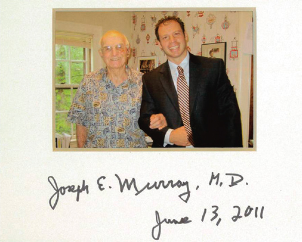
C.R.G. would like to dedicate this article in memory of Dr. Joseph Murray, for without his foresight and emphasis on large animal preclinical investigation, together with an intense passion for craniomaxillofacial surgery, none of this would be possible (Fig. 13).
FIGURE 13.
A memorable photograph taken within Dr. Murray’s office during an inspirational visit to his home in June 2011 (Boston, MA).
This study was funded in part by the American Society of Maxillofacial Surgery’s (2011 ASMS Basic Science Research grant), American Association of Plastic Surgeons (2012–2014 Furnas’ Academic Scholar Award), the Accelerated Translational Incubator Program at Johns Hopkins (funded by the National Institute of Health), and internal research and development funds from Johns Hopkins Applied Physics Laboratory.
This publication was made possible by the Johns Hopkins Institute for Clinical and Translational Research (ICTR), which is funded in part by the National Center for Advancing Translational Sciences (NCATS), a component of the National Institutes of Health (NIH), and NIH Roadmap for Medical Research. Its contents are solely the responsibility of the authors and do not necessarily represent the official view of the Johns Hopkins ICTR, NCATS, or NIH (NCATS grant UL1TR000424-06).
Footnotes
The views expressed in this article are those of the authors and do not necessarily reflect the official policy, position, or endorsement of the Department of the Navy, Army, Department of Defense, or the US Government.
Supplemental digital content is available for this article. Direct URL citations appear in the printed text and are provided in the HTML and PDF versions of this article on the journal’s Web site (www.jcraniofacialsurgery.com).
The authors report no conflicts of interest.
REFERENCES
- 1.Gordon CR, Siemionow M, Papay F, et al. The world’s experience with facial transplantation: what have we learned thus far? Ann Plast Surg. 2009;63:572–578. doi: 10.1097/SAP.0b013e3181ba5245. [DOI] [PubMed] [Google Scholar]
- 2.Siemionow M, Ozturk C. An update on facial transplantation cases performed between 2005 and 2010. Plast Reconstr Surg. 2011;128:707e–720e. doi: 10.1097/PRS.0b013e318230c77b. [DOI] [PubMed] [Google Scholar]
- 3.Pomahac B, Pribaz J, Eriksson E, et al. Three patients with full facial transplantation. N Engl J Med. 2011;366:715–722. doi: 10.1056/NEJMoa1111432. [DOI] [PubMed] [Google Scholar]
- 4.Siemionow MZ, Papay F, Djohan R, et al. First U.S. near-total human face transplantation: a paradigm shift for massive complex injuries. Plast Reconstr Surg. 2009;125:111–122. doi: 10.1097/PRS.0b013e3181c15c4c. [DOI] [PubMed] [Google Scholar]
- 5.Singhal D, Pribaz JJ, Pomahac B. The Brigham and Women’s Hospital face transplant program: a look back. Plast Reconstr Surg. 2011;129:81e–88e. doi: 10.1097/PRS.0b013e31823621db. [DOI] [PubMed] [Google Scholar]
- 6.Dorafshar AH, Bojovic B, Christy MR, et al. Total face, double jaw, and tongue transplantation: an evolutionary concept. Plast Reconstr Surg. 2012 doi: 10.1097/PRS.0b013e3182789d38. [DOI] [PubMed] [Google Scholar]
- 7.Gordon CR, Susarla SM, Peacock ZS, et al. Le Fort–based maxillofacial transplantation: current state of the art and a refined technique using orthognathic applications. J Craniofac Surg. 2012;23:81–87. doi: 10.1097/SCS.0b013e318240ca77. [DOI] [PubMed] [Google Scholar]
- 8.Gordon CR, Susarla SM, Peacock ZS, et al. Osteocutaneous maxillofacial allotransplantation: lessons learned from a novel cadaver study applying orthognathic principles and practice. Plast Reconstr Surg. 2011;128:465e–479e. doi: 10.1097/PRS.0b013e31822b6949. [DOI] [PubMed] [Google Scholar]
- 9.Gordon CR, Swanson EW, Susarla SM, et al. Overcoming cross-gender differences and challenges in Le Fort–based, craniomaxillofacial transplantation with enhanced computer-assisted technology. Ann Plast Surg. 2013;71:421–428. doi: 10.1097/SAP.0b013e3182a0df45. [DOI] [PMC free article] [PubMed] [Google Scholar]
- 10.Cutting C, Bookstein FL, Grayson B, et al. Three-dimensional computer-assisted design of craniofacial surgical procedures: optimization and interaction with cephalometric and CT-based models. Plast Reconstr Surg. 1986;77:877–887. doi: 10.1097/00006534-198606000-00001. [DOI] [PubMed] [Google Scholar]
- 11.Antony AK, Chen WF, Kolokythas A, et al. Use of virtual surgery and stereolithography-guided osteotomy for mandibular reconstruction with the free fibula. Plast Reconstr Surg. 2011;128:1080–1084. doi: 10.1097/PRS.0b013e31822b6723. [DOI] [PubMed] [Google Scholar]
- 12.Mehra P, Miner J, D’Innocenzo R, et al. Use of 3-D stereolithographic models in oral and maxillofacial surgery. J Maxillofac Oral Surg. 2012;10:6–13. doi: 10.1007/s12663-011-0183-3. [DOI] [PMC free article] [PubMed] [Google Scholar]
- 13.Sinn DP, Cillo JE, Jr, Miles BA. Stereolithography for craniofacial surgery. J Craniofac Surg. 2006;17:869–875. doi: 10.1097/01.scs.0000230618.95012.1d. [DOI] [PubMed] [Google Scholar]
- 14.Bell RB. Computer planning and intraoperative navigation in cranio-maxillofacial surgery. Oral Maxillofac Surg Clin North Am. 2010;22:135–156. doi: 10.1016/j.coms.2009.10.010. [DOI] [PubMed] [Google Scholar]
- 15.Beumer HW, Puscas L. Computer modeling and navigation in maxillofacial surgery. Curr Opin Otolaryngol Head Neck Surg. 2009;17:270–273. doi: 10.1097/MOO.0b013e32832cba7d. [DOI] [PubMed] [Google Scholar]
- 16.Cinquin P, Troccaz J, Demongeot J, et al. IGOR: image guided operating robot. Innov Technol Biol Med. 1992;13:374–394. [Google Scholar]
- 17.Brown EN, Dorafshar AH, Bojovic B, et al. Total face, double jaw, and tongue transplant simulation: a cadaveric study using computer-assisted techniques. Plast Reconstr Surg. 2012;130:815–823. doi: 10.1097/PRS.0b013e318262f2c9. [DOI] [PubMed] [Google Scholar]
- 18.Santiago G, Susarla S, Al Rakan M, et al. Establishing cephalometric landmarks for the translational study of Le Fort–based facial transplantation in swine: enhanced applications using computer-assisted surgery and custom cutting guides. Plast Reconstr Surg. 2013 doi: 10.1097/PRS.0000000000000110. In press. [DOI] [PMC free article] [PubMed] [Google Scholar]
- 19.DiGioia AM, Jaramaz B, O’Toole RV. An integrated approach to medical robotics and computer assisted surgery in orthopaedics; Paper presented at the Proc. 1st Int. Symposium on Medical Robotics and Computer Assisted Surgery; Pittsburgh, PA. 1994. [Google Scholar]
- 20.DiGioia A, Kanade T, Wells P, et al. NSF Workshop on Medical Robotics and Computer-Assisted Medical Interventions (RCAMI) Bristol, England: Shadyside Hospital; 1996. [Google Scholar]
- 21.Nolte LP, Visarius H. Computer Assisted Orthopaedic Surgery. Seattle, WA: Hofgrefe & Huber; 1996. [Google Scholar]
- 22.Taylor RH. Medical robotics. In: Nof SY, editor. Handbook of Industrial Robotics, Second Edition. New York: Wiley; 1999. pp. 1213–1230. [Google Scholar]
- 23.Taylor RH, Paul HA, Cutting CB, et al. Augmentation of human precision in computer-integrated surgery. Innov Technol Biol Med. 1992;13:450–459. [Google Scholar]
- 24.Taylor RH, Lavallee S, Burdea G, Mosges R. Computer-Integrated Surgery. Cambridge, MA: MIT Press; 1996. [PubMed] [Google Scholar]
- 25.Taylor RH, Joskowicz L. Computer-integrated surgery and medical robotics. In: Kutz M, editor. Standard Handbook of Biomedical Engineering & Design. McGraw-Hill; 2002. pp. 29.23–29.45. [Google Scholar]
- 26.Taylor RH, Stoianovici D. Medical robotics in computer-integrated surgery. IEEE Trans Robot Autom. 2003 special issue on medical robotics. In press. [Google Scholar]
- 27.Cleary K, Peters TM. Image-guided interventions: technology review and clinical applications. Annu Rev Biomed Eng. 2010;12:119–142. doi: 10.1146/annurev-bioeng-070909-105249. [DOI] [PubMed] [Google Scholar]
- 28.Gordon C. Le Fort–based maxillofacial vascularized transplantation. In: Naini F, Gill D, editors. Orthognathic Surgery: Principles, Planning, and Practice. Vol under review. Wiley-Blackwell; 2014. [Google Scholar]
- 29.Lavallee S, Troccaz J, Sautot P, et al. Computer-assisted spinal surgery using anatomy-based registration. In: Taylor RH, Lavallee S, Burdea G, Mosges R, editors. Computer-Integrated Surgery. Cambridge, MA: MIT Press; 1996. pp. 425–449. [Google Scholar]
- 30.Lepisto J, Armand M, Armiger R. Periacetabular osteotomy in adult hip dysplasia—developing a computer aided real-time biomechanical guiding system (BGS) Suomen Ortop Traumatol. 2008;31:186–190. [PMC free article] [PubMed] [Google Scholar]
- 31.Armand M, Armiger R, Waites M, et al. A guidance system for intraoperatively updating surgical-plans during periacetabular osteotomy: development and cadaver tests; Paper presented at CAOS; 2006; Montreal, Canada. [Google Scholar]
- 32.Papadaki ME, Troulis MJ, Glowacki J, et al. A minipig model of maxillary distraction osteogenesis. J Oral Maxillofac Surg. 2010;68:2783–2791. doi: 10.1016/j.joms.2010.06.179. [DOI] [PubMed] [Google Scholar]
- 33.Gateno J, Seymour-Dempsey K, Teichgraeber JF, et al. Prototype testing for a new bioabsorbable Le Fort III distraction device: a pilot study. J Oral Maxillofac Surg. 2004;62:1517–1523. doi: 10.1016/j.joms.2004.08.005. [DOI] [PubMed] [Google Scholar]
- 34.Shigeta Y, Ogawa T, Ando E, et al. Analysis of masticatory muscle condition using the 4-dimensional muscle model for a patient with square mandible. Stud Health Technol Inform. 2005;111:468–472. [PubMed] [Google Scholar]
- 35.Armand M, Lepistö J, Merkle A, et al. Computer-aided orthopaedic surgery with near real-time biomechanical feedback. APL Tech Digest. 2004;25:242–252. [Google Scholar]
Associated Data
This section collects any data citations, data availability statements, or supplementary materials included in this article.


