Abstract
Recently reported nanofluidic diodes with highly nonlinear current-voltage characteristics offer a unique possibility to construct different biosensors. These sensors are based on local changes of the surface charge on walls of single conical nanopores induced by binding of an analyte. The analyte binding can be detected as a change of the ion current rectification of single nanopores defined as a ratio of currents for voltages of one polarity, and currents for voltages of the opposite polarity. In this Article we provided both modeling and experimental studies of various biosensing routes based on monitoring changes of the rectification degree in nanofluidic diodes used as a biosensing platform. A prototype of a sensor for the capsular poly γ-D-glutamic acid (γDPGA) from Bacillus anthracis is presented. The nanopore used for the sensing was locally modified with the monoclonal antibody for γDPGA. The proof of principle of the rectification degree based sensing was further shown by preparation of sensors for avidin and streptavidin. Our devices also allowed for determination of isoelectric point of the minute amounts of proteins immobilized on the surface.
Introduction
Nature developed very sensitive and precise control over the ionic and molecular transport across biological membranes. Transmembrane transport occurs via biological channels and pores, which lie at the heart of virtually any functioning living cell.1 These channels, when used outside of a biological organism, could open a route to a variety of breakthrough applications in the field of biotechnology e.g. in biosensing and separations. Since these channels are rather fragile and can function only when inserted in a lipid membrane it is very hard to use them directly in man-made systems. It is very attractive to construct solid-state pores, which would exhibit similar properties to those of biological channels, but would be stable in a variety of conditions such as temperature, pH, ionic strength, etc. The emerging fields of nanofluidics and solid-state nanopores offer a variety of different platforms for fabrication of such systems.2–10 Using biological channels as a model, researchers have tried to prepare responsive nanoporous devices. Ion current modulation through such pores was achieved by a variety of external stimuli such as light11, pH12, and different molecules3,13,14,15 (e.g. DNA and proteins).
We have focused on ion current modulations induced by various molecules in single nanopores as the basis for label free biosensing. Measuring ion current is inexpensive (e.g. compared to the surface plasmon resonance or fluorescence microscopy instrumentation) and can be performed very precisely down to several pA, or in some systems even down to fractions of pA. 16 Moreover, the nanopore-based detecting technique can be parallelized by construction of nanochannel arrays so that several molecules are detected simultaneously.
There are different approaches for constructing a nanoporous biosensor, in which the detection signal would be based on current modulations. Crudely, single nanopore sensors can be divided into two classes. The first class is based on measuring transient changes of ion current, which occur when single molecules pass through a nanopore. In the second “steady-state” approach, the nanopore walls are decorated with recognition sites for a specific analyte that is present in a solution; changes in the current-voltage curves before and after introduction of an analyte to the solution are monitored.
Presence of analyte in a nanopore can cause two effects to occur: i) volume exclusion14,17 when the analyte is large enough compared to the pore opening to cause a partial or complete occlusion of a pore, and ii) modification of the surface charge occurring upon binding of the analyte to the pore walls. 18,19,20 In those two described cases of steric and electrostatic influence, the presence of an analyte in a pore is detected as the change in the magnitude of an ionic current passing through a nanochannel.
Both of these effects can be used for sensing. The second, electrostatics-based effect may be more robust and versatile compared to the steric approach because the electrostatic approach can be applied to nanopores of various pore openings. The possibility of using the electrostatic modulations in building a sensor is further supported by extensive studies of transport properties at the nanoscale and the effect of surface charges on ion currents through a nanochannel, especially if the nanochannel radius is comparable to the Debye length of a given bulk solution.21 In the volume exclusion principle on the other hand, the current change is proportional to the decrease of the effective nanochannel cross-section, which is induced by the analyte’s presence in the pore.22,23,24,25 Thus in order to observe an effective nanochannel blockage, the size of the analyte has to be comparable to the nanopore radii, which in turn requires a prior fine tuning of a nanochannel diameter for different analytes.17 The fine-tuning of a pore size might not always be possible, since an analyte to be detected is often not well characterized or it can be present in a range of molecular masses thus in a range of sizes.
Nanopore sensors using the electrostatic principle constructed thus far consisted of a nanopore whose entire pore walls were modified with recognition molecules, for example with biotin in a system that detected avidin or streptavidin.20 The biosensor that we present here is based on single conically shaped nanopores whose pore walls were modified with a recognition agent only very locally - in the region close to the narrow opening, called the tip. We expect that in this case smaller numbers of analyte molecules are needed to induce ion current change, which may improve the detection limit of the system. Moreover, this template allows us to take advantage of the formation of irregular surface charge patterns that could be created when an analyte binds to the recognition sites only at the narrow opening.
As a template for our sensor we chose an irregular surface charge pattern that creates an ionic diode. An ionic diode for example consists of a junction between a part of the pore walls with positive surface charges and a zone with negative surface charges. Ionic diode is a promising template for a sensor because it is characterized by very high rectification degrees, Q thus a ratio of currents recorded for voltages of one polarity and currents recorded for voltages of the opposite polarity
| (1) |
Ion current through these diodes also depends on the surface charge density. Changes of the surface charge due to the analyte binding at the narrow opening should be very easily detected as a change of the rectification degree Q.
For preparation of the sensor we used single conically shaped nanopores in polymer films. The nanopore was modified by recognition agent only at the narrow opening using the method of surface patterning reported by us before.26
As a proof of principle for the biosensor functioning we prepared a system that detected avidin and streptavidin. As the next step, we designed an ionic diode based sensor for the poly-γ-glutamic acid (γDPGA) from the capsule of Bacillus anthracis. The γDPGA sensor consists of a single conical nanopore whose tip is modified with a monoclonal antibody (mAb) for the capsular γDPGA.27 The system of γDPGA and its mAb plays an important role in designing a vaccine against anthrax as well as in monitoring infection with anthrax.27
The biosensor design was supported by the Poisson-Nernst-Planck modeling of ion current through single conical nanopores with various geometries and surface chemistries. The modeling confirms the advantages of using ionic diodes as a template for the biosensor.
Experimental
Nanochannel preparation
Single conical nanopores were prepared in 12 micrometers thick polyethylene terephthalate (PET) films by the track-etching technique described before.8 The process consists of irradiation of the material with single energetic heavy ions and subsequent chemical etching of the irradiated foils. The conical shape is obtained by performing the etching only from one side, while the other side of the foil is in contact with an acidic stopping medium.8 The etching process is monitored by measuring the transmembrane current. At the beginning of the etching process, the current is zero. Recording a finite current indicates that the etching occurred through the whole thickness of the foil creating a pore. After observing a finite current, the etching was continued from both sides for about 10 minutes. This resulted in nanopores with ~25 nm radius, thus significantly larger than conical nanopores used in our previous studies (see e.g. Ref. 8,17,26). Estimation of the pore diameter was performed after the etching, using the conductivity method described previously.8 The method consists of measuring resistance of the pores in 1 M KCl, and at the voltage range between −1 V and +1V, where the current-voltage curves are linear. The tip opening diameter was then estimated using the following equation:
| (2) |
where ρ is the specific resistivity of the electrolyte solution, (ρ= 0.1 Ωm for 1M KCl), L is the pore length (L = 12μm), A is the base radius, and a indicates the tip radius. The base radius is estimated from the bulk etch rate that for PET in 9 M NaOH and room temperature equals 2.13 nm/min. 8 Equation 2 simplifies to the relation used in previous studies8 for the a≪A approximation.
Chemical modification procedures
As a result of chemical etching, the walls of PET pores contain carboxyl groups at the density of 1 per nm2. 28 These carboxyls provide a convenient way for attachment of various chemical groups via coupling with primary amines by 1-Ethyl-3-[3-dimethylaminopropyl] carbodiimide hydrochloride (EDC).29 In order to perform targeted modification of the pores at the narrow opening, we used the procedure developed by us before for ionic diodes.26 If the modifying reagents are placed only on one side of a membrane, the concentrations of the reagents are high at this side, and decay hyperbolically along the pore axis due to the conical shape of a nanopore. The modification can therefore occur only at the region close to the small opening where the reagents’ concentration is sufficiently high. In the remaining parts of the pore, the concentration is too low for the chemical modification to occur, and the pore wall retains the majority of COOH groups.
A two-step procedure was applied to modify the surface chemistry of the pore walls: (i) activation of the surface COOH with N-hydroxysulfosuccinimide (S-NHS) from one side of the membrane, and (ii) incubation of the membrane with a given molecule containing a primary amino group.
Activation by succinimide
A solution of 0.01 M of EDC and 0.02 M of N-hydroxysulfosuccinimide (S-NHS) was prepared in 0.5 M MES buffer (2-(N-Morpholino) ethanesulfonic acid monohydrate), pH = 5.5. The reagents were purchased from Pierce and used as received. The solution was introduced only at the nanochannel tip side, while the other side of the membrane was in contact with 0.5M MES solution. The activation time was kept constant at 10 min, which was followed by a thorough wash of the membrane with 0.1 M MES buffer solution from both sides.
Modification of the tip of a conical nanopore with biotin and 2-methoxyethylamine
A solution of aminated biotin (Pierce #21346) and 2-methoxyethylamine was prepared in 0.1 M MES, pH=5.5 to final concentrations of 0.013 M and 0.03 M, respectively. A membrane which had been prior asymmetrically activated with S-NHS was overnight incubated from both sides with the aminated molecules. The membranes were subsequently thoroughly washed with 100 mM KCl solution.
Immobilization of avidin and streptavidin at the tip of a conical nanopore
A 0.5 μM solution of avidin (Aldrich A9275) and 0.5 μM solution of streptavidin (Aldrich S0677) were prepared in 100 mM KCl, pH 5.5. A solution of a given protein was added on both sides of a nanopore with a biotinylated tip. Immobilization time was varied from 2 hours to overnight.
Modification of a tip of a conical nanopore with the monoclonal antibody (F26G3) to the poly- γ-glutamic acid
1 mg of the monoclonal antibody F26G3 (used as received) was dissolved in 3 ml of 100 mM KCl pH 5.5. This gave the final concentration of 0.33 mg/ml. The resulting solution was added to the nanopore that had been previously activated at the tip with S-NHS. The modification reaction was carried out overnight. After the modification, the nanopores were thoroughly washed with an ample amount of 100 mM KCl solution.
Sensing γDPGA
2.7 mg of γDPGA was dissolved in 3 ml of 100 mM KCl pH5.5. This solution was added on both sides of single conical nanopores whose tips had been previously modified with mAb F26G3. The incubation time of 3 hours was kept constant for all examined samples. Washing the membrane with 100 mM KCl was performed afterwards.
The Poisson-Nernst-Planck modeling of ion currents through single conical nanopores
Calculations of ion current were performed using the COMSOL Multiphysics 3.4 package. At the charged walls, we used a triangular mesh with 0.1 nm spacing. We would decrease the meshing at the bulk reservoirs and at the nanochannel interior to the point where no current change was observed upon further mesh decrease. Details of the calculations can be found elsewhere.21,30 The reliability of the calculations was confirmed by comparing analytically solvable cases with their numerical treatment. An excellent agreement between the analytical and numerical approaches has been demonstrated.21,30
Results and Discussion
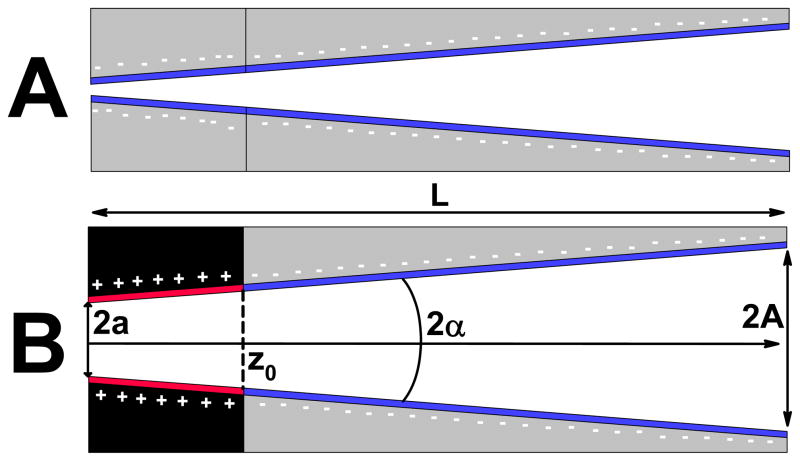
As the main detection signal in our biosensing system, we wanted to use changes of ion current rectification degree occurring due to interactions of an analyte present in a solution with the pore walls. There are two nanopore platforms that potentially could be used as a template for this rectification degree based sensor. First, conical nanopores with homogenous surface charges were found to exhibit asymmetric current-voltage curves, whose degree and direction of rectification are surface-charge dependent (Fig. 1A). Currents for voltages of one polarity are several times higher than currents recorded for voltages of an opposite polarity. Recently prepared ionic diodes (Fig. 1B), which contain a dissimilar surface charge pattern, could become an alternative platform for the sensor. An ionic diode could be treated as a perfect rectifier: it allows the ion flux to occur only in one direction, blocking it in the other.
Figure 1.
Schematics of rectifying platforms that can be used as a template for presented biosensor. A) A homogeneously charged conical nanopore. B) A conical bipolar diode. Ionic diodes were denoted in a following way: first the surface charge of a tip (small opening) followed by the surface charge of the base (large opening). For example, for the configuration shown in (B), the tip is positive, and the base is negative, thus in our notation this diode is abbreviated as {+;−}. The symbols have the following meaning: A – base radius, a – tip radius, α - divergence angle of a cone, z0 – transition zone for the surface charge change. For all numerical calculations, the surface charge was assumed to change abruptly at z0.
We start the article with theoretical considerations on the optimal geometry and surface chemistry for the biosensor template, thus a nanoporous system that assures maximum rectification degrees.
Theoretical modeling: defining various platforms for biosensing
Uneven geometry of a nanochannel, surface charge or a combination of both result in ion current rectification (Eq. (1)). Many biological channels rectify the current, and several rectifying solid state nanopores were fabricated as well.8,31,32 The simplest example of such a rectifying artificial system is a conical nanopore with homogeneous surface charges.8 The rectification mechanism has been extensively analyzed and its physical basis is well understood. Using different physical approaches, the rectification effect can be explained through a ratchet model33 or via the Poisson-Nernst-Planck modeling34,35,36 that revealed similarity of the conical nanopores to the Schottky diode.30 We will consider a rectifying conical nanochannel with homogeneous surface charges (Fig. 1A) as a potential starting point for a new type of biosensor, whose main detection signal is the rectification degree.
In order to calculate the ionic currents through conical nanopores and thus to determine the rectification degree Q, we numerically solved the three dimensional (3D) Poisson-Nernst-Planck equations 30:
| (3) |
where φ is the electric potential, Ci stands for concentration of either positive or negative ions i, e is the electron charge, kB denotes the Boltzmann constant, and zi is the charge of the ith ion. The calculations details can be found elsewhere.21,30 For simplicity, we ignored electroosmosis (i.e. the Navier - Stokes equation) since according to our previous analysis, its contribution to the total current is small.21,30
Conical nanopores with homogeneous surface charges
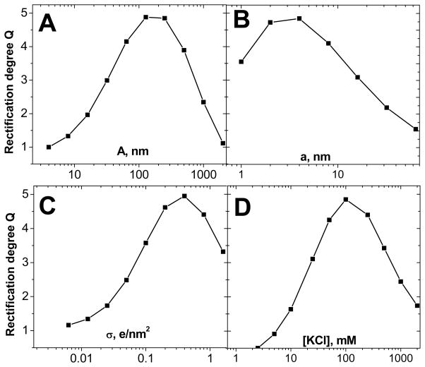
Figure 2 summarizes results of our numerical calculations showing how the rectification degree Q calculated at ±1V depends on various parameters: base radius, A (A), tip radius, a, (B), surface charge, σ (C), and bulk concentration of electrolyte (KCl), Cbulk (D). All calculations were performed for conically shaped nanopores with homogenous surface charges and length L of 12 micrometers (Fig. 1A). The calculations revealed that the maximum value of the rectification degree, which one can obtain for the parameters studied here does not exceed 5. It is also important to notice that each part of the figure shows a distinct maximum for the rectification degree. For example, one can find a value of the tip diameter for which the highest value of Q is obtained. It is because a very small tip opening results in a significant voltage drop at the nanochannel entrance due to the access resistance and polarization effects, 21,30 which leads to lower rectification degrees. On the other hand, when the tip opening becomes much larger than the Debye length, the pores lack the appreciable ionic selectivity and thus they cease to rectify.21 Thus there is an optimum value of the tip radius for which the greatest rectifications degrees are obtained (Fig. 2A). Analogous arguments can be applied to other parameters i.e. σ, Cbulk and A.
Figure 2.
Numerically calculated rectification degrees (Eq. (1) at 1V) of a homogeneously charged conical nanopore as a function of A) base radius, A B) tip radius, a C) surface charge, σ, and D) bulk concentration of KCl. The following values were used Cbulk = 0.1M, σ = −0.5e/nm2, A = 250nm, a = 4nm, and L = 12μm, unless the parameter was varied. The calculations were performed by numerically solving the 3D Poisson-Nernst-Planck equations. Our analysis showed that it was impossible to achieve rectification degrees higher than 5 for the examined range of the varying parameters, at least for our experimental nanochannel length of L = 12μm. Note that every graph has a maximum due to the interplay of the Debye length and the polarization effect at the nanopore entrance (including access/Hall resistance).
Biosensing with homogeneously charged conical nanopores would have to be performed in a way which changes the entire surface charge of the pore walls upon binding of the analyte. One could for example detect switching the surface charge from positive to negative or vice versa. It is because, with a ground electrode placed at the narrow opening of a pore, a negatively (positively) charged nanopore has larger currents for negative (positive) voltages.37 Exposing the pore to analyte which upon binding switches the surface charge of the pore walls (thus it carries a charge that is opposite to the charge of the pore walls) would therefore cause a flip in the current-voltage curve. Our modeling showed that the rectification degree in this case could be changed in the range of 5 ≤ Q ≤ 1/5 which is expected to give sufficient flexibility and sensitivity. The ratios of rectification degrees before and after analyte binding could thus reach 25.
It would also be possible to detect analytes that cause lowering or increase of the surface charge density.38 Since rectification degrees of homogeneously charged nanopores are rather low, change of the value of σ without switching its sign, would cause only a rather small change in Q between 1 and ~5 (Fig. 2 C). Changing the value of σ could also be detected by monitoring the current magnitude. For example, lowering the surface charge from σ ~ −1e/nm2 to σ = 0 decreases the ionic current by a factor of ~5. A fivefold change in the current value should be easily detected experimentally, however for reasons explained further, a neutral surface is practically unachievable at least in our experimental setup.
There are pore geometries different from the conical one, which have superior rectification properties,39 but such shapes had not been achieved yet experimentally.
Nanofluidic diodes
Nanofluidic diodes are formed when a nanochannel has an uneven surface charge density along the nanochannel length (Fig. 1B).26,30,40,41 Diodes can be made bipolar (BP)26 or unipolar (UP) 41, and we investigated the applicability of both types of diodes for building a biosensor. In our previous work we showed that high rectification degrees can be achieved for nanofluidic diodes in a wide range of parameters, such as pore radii, surface charge, and ionic strength.30 Under a forward bias, the current flows freely through the device, creating an open state of a diode, while the reverse bias results in a formation of the depletion zone with a suppressed current, thus a closed state of a diode. High rectification degrees Q reaching several hundreds offer a unique possibility to monitor the change in the rectification degree upon the analyte binding. Functioning of bipolar ionic diodes is also well-understood as a function of pore radii and surface charge.30
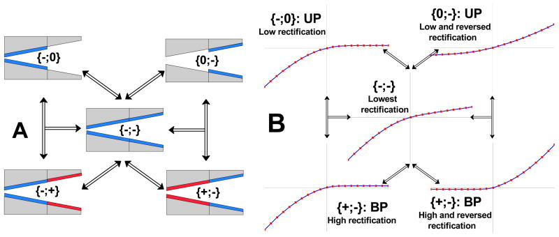
Figure 3A shows various types of diodes and rectifiers, whose surface charge is described in the following way: in square brackets we write first the surface charge of the tip, then we indicate the surface charge of the base (large opening). For example, for the device shown in Fig. 1B, the tip is positive, the base is negative, thus in our notation this diode is abbreviated as {+;−}. Figure 3B contains schemes of current-voltage curves of ionic devices shown in Fig. 3A.
Figure 3.
Schemes of various surface charge patterns that could lead to preparation of ionic diodes together with their current-voltage curves. The arrows indicate possible transitions between different surface charge patterns, which can be induced upon binding of one type of analyte to the pore walls. A) Schematics of unipolar (UP) diodes are in the upper row, while bipolar diodes (BP) are shown in the bottom row. A homogeneously charged conical nanopore is shown in the middle. B) Behavior of current-voltage curves of the nanopores shown in (A). BP diodes have superior rectification properties compared to UP diodes i.e. BP diodes produce higher rectification degrees. A conical nanochannel with homogenous surface charges shows the lowest rectification degree. Note that in the transition from a homogenously charged conical nanopore to the {+;−} and {0;−} configurations, the current-voltage curve flips, which allows for a very easy detection of the analyte that induced this change. See text for details.
Bipolar (BP) nanofluidic diodes
A bipolar diode is formed when the surface charge changes its sign along the nanochannel coordinate (Fig. 1B). The point where the surface charge changes its sign is denoted as z0, so that σ = σ0 for [0, z0] and σ = −σ0 for [z0, L]. The position of z0 is one of the parameters that strongly influence the rectification properties of the device. In cylindrical or slit nanochannels, in order to get the maximum rectification degree Q, z0 has to be located exactly in the middle of the device length, i.e. . 30 For our conical geometry, using a similar analytical approach as the one reported in our previous article, we found the following analytical relation for valid in the approximation a≪A:
| (4) |
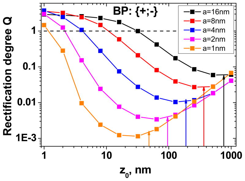
Thus the optimal position of the transition zone z0 is proportional to the tip radius, a, and the device length, L, and it is inversely proportional to the base radius, A. We performed numerical calculations of the rectification degree for a BP diode based on a conical pore as a function of a tip radius and the position of the transition zone z0 (Fig. 4). Note that after the formation of a diode with positively charged tip, the current-voltage curve flipped compared to the original negatively charged pore. Our calculations also confirmed the strong dependence of the rectification degree on the tip radius. Notably, the analysis confirmed applicability of Eq. 4 for predicting the position of the optimal z0 (see the arrows in Fig. 4). The ratio of the rectification degrees before and after the diode formation (thus of a homogeneously charged conical pore and a diode) spans a range from ~3000 at a = 1nm to ~50 at a = 16nm. The value of 3000 was obtained as a ratio of the rectification degree in Fig. 2B for a=1 nm (Q = ~3), and the maximum rectification in Fig. 4 (Q = ~0.001). The calculations were performed for the following values of the parameters: σ = −0.5e/nm2, L = 12μm, A = 250nm and Cbulk = 0.1M (validity of Eq. (4) is also shown in the Supporting Information for a range of A and L values). These high rectification degree changes make the BP diode a superior platform for biosensing compared to a homogeneously charged conical pore. It is important to note that the rectification degrees can be substantially higher for larger surface charge densities or lower bulk concentrations. The optimal position of the transition zone, , does not however change with either of these two parameters, thus Eq. 4 provides the best estimate for the optimal transition zone location for a wide range of external parameters. Experimentally, we can easily tune the location of z0; it is much more difficult however to obtain a very sharp transition between positive and negative surface charges, as we assumed in the PNP modeling.26
Figure 4.
Numerically calculated rectification degrees of bipolar (BP) diodes based on single conically shaped pores, as a function of the transition zone location (z0), and the tip radius (a). Only one configuration {+;−} is shown since the rectification degree of the device {−;+} can be calculated as the reverse of the shown values. The arrows indicate the position of the transition zone that assures the highest rectification degree, as estimated by Eq. 4. The calculations were performed for L = 12μm, A = 250nm, Cbulk = 0.1M and σ= −0.5e/nm2.
Unipolar (UP) nanofluidic diode
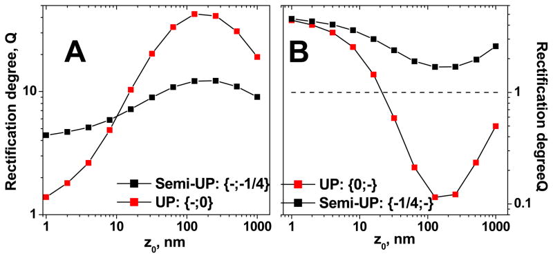
The BP diodes are symmetric, i.e. rectification in the {+;−} configuration is exactly reversed to this of the device {−;+}. Unipolar diodes (UP) lack this kind of symmetry thus behavior of the device {0;−} is different than properties of the diode {−;0}. It is also important to mention that the depletion zone for a UP diode is predominantly confined to the uncharged segment and is much longer than the depletion zone of a BP diode.30 Thus a diode {−;0} should show larger rectification degrees than a diode {0;−} since the uncharged nanochannel segment is longer for the former configuration. Figure 5 shows the dependence of the rectification degree on the tip radius and z0, for the two UP diodes: {−;0} and {−;0}. The calculations were performed for the same parameters as these used for a BP diode thus: σ = −0.5e/nm2, L = 12μm, A = 250nm and Cbulk = 0.1M. Note that Eq. 4 still provides the optimal position of the transition zone that is in a good agreement with the numerical calculations (arrows in Fig. 5). Although Eq. 4 was derived for a BP diode, it seems to hold true for a UP diode as well. As expected, UP diodes have lower rectification degrees than BP diodes but overall they show a very similar qualitative dependence on the diode opening diameter i.e. for larger tip radii, lower values of Q are observed.
Figure 5.
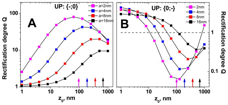
Numerically calculated rectification degrees of conical unipolar (UP) diodes as a function of the transition zone location (z0), and the tip radius (a). The arrows show the position of the transition zone that assures the highest rectification degree, as estimated by Eq. 4. A) Rectification degrees of the device whose tip is charged and the base is uncharged – {−;0}. B) Rectification degrees for the {0;−} device. The calculations were performed for L = 12μm, A = 250nm, Cbulk = 0.1M, and σ= −0.5e/nm2.
Our starting point for the biosensor preparation was a conically shaped pore with carboxyls on the pore walls. Achieving a complete neutralization of the pore walls appeared to be an experimental challenge in our system. There would always be a residual negative surface charge when neutralizing the negatively charged pores. This happened presumably due to steric difficulties of accessing some carboxyls groups by the chemicals (S-NHS and EDC) which were used for the modification. The etched polymer surface in 9M NaOH can be quite rough and some carboxyls could be “buried” under the surface. Thus we also looked at a semi unipolar diode, i.e. instead of σ = 0, we used ¼ of the original surface charge (i.e. ¼ of −0.5 e/nm2): {¼−;−} and {−;¼−}. We considered the 75% conversion of the surface carboxyls to uncharged groups a good chemical yield for our pores. As expected, such semi-UP diodes showed rectification degrees which were significantly lower than the values of Q for UP diodes with {−,0} and {0,−} (Fig. 6). Interestingly, rectification properties of such semi-UP diodes appeared to be only slightly different from behavior of homogeneously charged conical nanopores. For example, rectification degree of a semi-UP diode is only 2 times larger than the value of Q for a conical homogeneously charged pore if the transition zone is located at . Moreover, for the {¼−;−} device, the flip in the current-voltage curve was not observed (Fig. 6B). Thus, as a good approximation, one can consider the semi-UP devices {¼−;−} {−;¼−} similar to conical pores {−;−}
Figure 6.
Comparison of unipolar diodes (UP), which consist of a charged zone and a zone that is neutral, to semi-UP diodes, which consist of two zones with surface charge of the same sign but different density. As evidenced by our experiments, a neutral surface (σ = 0) is difficult to achieve for our pores, we calculated current-voltage curves when 75% of the surface carboxyls were converted to uncharged methoxy groups. A) Comparison of the rectification degree for {−,0} and {−;¼−} diodes. B) Rectification degrees Q for {0,−} and {¼−;−} diodes. As followed from this figure, semi-UP conical diodes are very similar in their behavior to initial conical pores, thus devices with the surface charge pattern {−;−}. The calculations were performed for L = 12μm, A = 250nm, Cbulk = 0.1M, and σ = −0.5e/nm2. The rectification degree was calculated for 1V. See text for details.
Different biosensing routes
Schematics of possible biosensing routes are shown in Fig. 3A together with sketches of corresponding current-voltage curves in Fig. 3B. We considered only one type of analyte which could bind to the nanochannel walls, i.e. the surface charge changes its sign or/and magnitude only at one region of the nanochannel. For example transition from the surface charge {−,0} to {+,−} is not considered since it would require two different molecules to bind to the walls. On the other hand, the transition {−,0} => {−,+} is possible because the surface charge is changed only at the right hand side of the pore. We note however that the development of a sensor which senses simultaneously two or more analytes in a single nanochannel is achievable.
For clarity of the presentation, the configurations of {+,0} and {0,+} are not shown, and such UP diodes differ from corresponding negative counterparts (i.e. {−,0} and {0,−}) only by the direction of rectification.
Our numerical modeling indicated that a bipolar diode had superior rectification degrees reaching several hundreds and thus we considered it the most suitable template for a proof of principle biosensing device. It should be very easy to detect a change of the rectification degree upon an analyte binding, especially if the current-voltage curves were flipped. Our unmodified conical nanopore is a weak rectifier, thus the transition {−;−}=> {+;−} should be most pronounced and easily detected.
The amount of analyte needed to change the rectification degree and/or to flip the current-voltage curve must also be taken into consideration. For a biosensor based on a conical nanofluidic diode (Fig. 1B), the surface area which needs to be modified by the analyte is much smaller compared to a situation when the entire pore walls were modified with a recognition agent. Since an optimal position of the transition zone z0 is only ~100nm away from the tip of the pore, placing the recognition agent at the tip side requires the smallest amount of analyte to create a diode surface charge pattern upon the analyte binding.
The detection limit of a diode sensor can be estimated as a ratio of the area of the tip zone that was modified with a recognition agent (black part in Fig. 1B) and an area occupied by a molecule to be detected, Sanalyte. For nanopores with a ≪ A, the ratio can be written as:
| (5) |
where N is the number of molecules required to modify the whole surface area of a pore tip (thus an area of a tapered cone {0, }), i.e. the detection limit. According to Eq. (5) one can improve the detection limit by increasing the base radii, diminishing the tip radii or/and the length of the pore. For example, Sanalyte for closed packed streptavidin/avidin protein is Sanalyte ≈ 30nm2. For a typical pore with a = 10 nm, L = 12 μm and A = 250 nm, Eq. 5 yields then N = 1500 molecules. Increasing the base diameter to A = 1000nm, and decreasing the tip diameter to a =8 nm yields a much improved N = 241 molecules. One has to remember that increasing the base radius results in poorer rectification properties, however the rectification degree Q can be tuned to a desired value by choosing the appropriate electrolyte concentration. In cases when sensing experiments have to be performed at various ionic strengths, working with smaller pore diameters will be necessary. Narrow pores ensure that the changes of rectification degree upon analyte binding occur in a wide range of electrolyte concentrations, including the physiological conditions of 100 mM.
It should be noted that the detection limit in all nanoscale systems is primarily limited by diffusion of the analyte from the bulk solution to the sensing elements in the pore. Even though the minimum number of molecules required for a measurable signal of a biosensor can be quite small, the diffusion time from a very dilute solution might be substantial, resulting in higher detection limits. Another issue to be considered is the binding constant between the recognition sites and the analyte, which determines the minimum concentration of the analyte that can be detected. In our future studies we would like to test the detection limit offered by our system in which various densities of recognition agents would be introduced.
As a proof of principle for the proposed biosensor we worked with well known proteins of avidin and streptavidin, which were sensed with single conical nanopores whose tip was modified with biotin. We also prepared a sensor for the bacterial γDPGA capsular antigen from the Bacillus anthracis. The sensor was based on single conically shaped nanopores which contained the monoclonal antibody (mAb) for γDPGA 27 at the tip. There are several possibilities to attach biotin and the mAb to the pore walls.17,20,26,38,42 We used the well known EDC and S-NHS chemistry.26,29,42
Preparation of a sensor for avidin
Avidin is a widely used positively charged protein with a very basic isoelectric point (pI) of ~11. The binding between biotin and avidin is one of the strongest known biochemical interactions.43 In order to prepare a sensor for avidin, a tip of single conical nanopores was modified with a mixture of aminated biotin and 2-methoxyethylamine. We used a mixture of the modification agents in order to ensure that avidin would not have steric difficulties to access the surface immobilized biotin.44 The spacer arm length for biotin used in our study is ~2 nm, which is sufficiently long for avidin binding. Presence of the 2-methoxyethyl group assures that all accessible sites for modification carboxyls are turned to uncharged terminated groups (from 2-methoxethylamine or biotin).
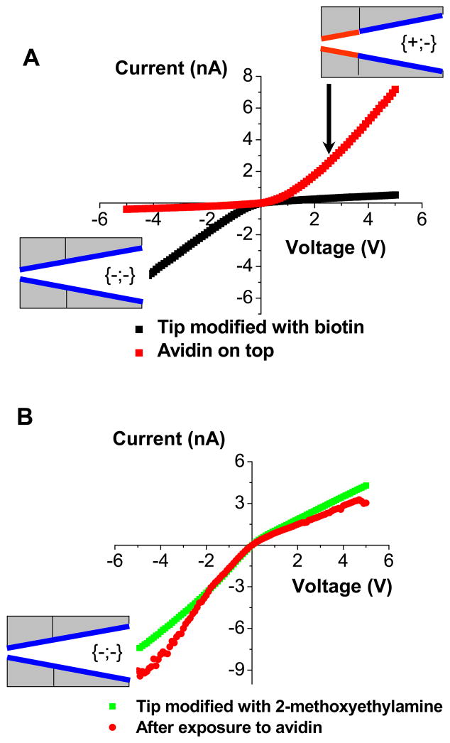
Modification of the tip of a conical nanopore with uncharged biotin resulted only in small or no change in the current-voltage curves - both the current magnitude and the current-voltage direction remained basically the same. As discussed above, even 75% conversion of the surface carboxyls to uncharged groups at the tip results only in ~30% current change. After the biotin modification we can thus still treat the pore as a homogeneously charged cone. This nanopore was subsequently exposed to a 0.5 μM solution of avidin for ~2 hours, and the current-voltage curve was re-measured in 10 mM KCl. Upon avidin binding, the rectification direction clearly changed (Fig. 7), indicating a successful formation of a bipolar diode junction, and a straightforward avidin detection. The fact that the rectification degree was almost exactly reversed and did not increase after avidin binding is probably due to the large size of the pore (radius of 30 nm) as well as a low effective surface charge in the pore tip (see Streptavidin detection discussed later). Theoretically, a BP diode created upon avidin binding should have superior rectification properties compared to a pore modified with biotin.
Figure 7.
Functioning of a nanofluidic diode sensor for avidin. A) Experimental current-voltage curves for a conical nanopore whose tip was modified with biotin before exposure to avidin (■), and after exposure to 0.5 μM solution of avidin (
 ). The current-voltage curves were measured in 10 mM KCl solution, pH = 5.5. The insets indicate the schematics of obtained surface charge patterns. Binding of avidin to the biotin modified pore resulted in the formation of the bipolar diode surface charge pattern. B) Studies of non-specific adsorption of avidin to a nanopore whose tip was modified with 2-methoxyethylamine. Current-voltage curve of this pore did not significantly change upon exposure to avidin, suggesting that non-specific interactions of the protein with the pore walls do not influence functioning of the sensor.
We have also performed a control experiment to evaluate the importance of non-specific adsorption of avidin on functioning of the biosensor. A tip of a conical nanopore was thus modified only with 2-methoxyethylamine, and the pore was subsequently incubated overnight with 0.5 μM solution of avidin. Fig. 7B shows current-voltage curves of the nanopore in 10 mM KCl before and after the exposure to avidin. The current-voltage curve did not flip upon the avidin exposure as it was observed with the biotin modified pores (compare with Fig. 7A). Moreover, the values of ion currents at low voltages remained basically unchanged as well. The experiments with 2-methoxyethylamine modified pores thus provided evidence that non-specific adsorption of avidin does not influence functioning of the sensor.
Preparation of a sensor for streptavidin
Streptavidin is another protein that binds very strongly to biotin. Streptavidin however has pI~6.3 when in solution, and pI~5 if bound to the surface immobilized biotin.45 Thus streptavidin can be made either positive or negative depending on the pH of the bulk solution. This feature is very attractive for our test platform, since if a tip of a pore is modified with biotin, upon streptavidin binding, the system will show pH dependent current-voltage characteristics. The point of the current-voltage flip could be correlated with the streptavidin isoelectric point. Checking the rectification direction as a function of the solution pH can be a basis for determination of isoelectric points of unknown proteins.
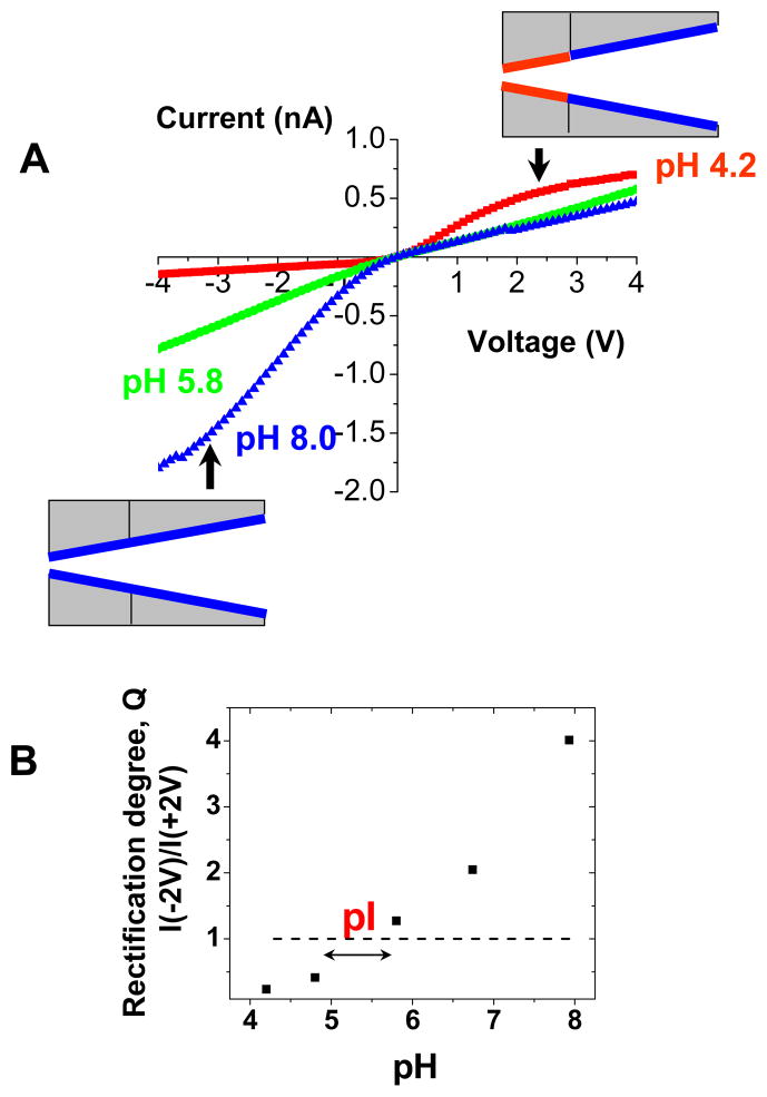
Immobilization of streptavidin on the pore walls was performed in an analogous way to the method applied for avidin. The tip of a conical pore was modified with a mixture of biotin and methoxy- groups with subsequent addition of streptavidin. As expected, binding of streptavidin caused the formation of a diode junction at acidic conditions when the protein was positively charged with Q < 1 (Fig. 8A). In basic conditions, the system could be treated as a simple negatively charged cone, thus the rectification degrees were larger than 1 (Q > 1). The system ceased to rectify (Q ~ 1) at pH~5.5 when streptavidin was almost neutral (Fig. 8B). Our experiments allowed us to conclude that the isoelectric point of streptavidin is ~5.5, which is in a good agreement with the previously found value for surface immobilized streptavidin.45
Figure 8.
Functioning of a diode sensor for streptavidin. A) Experimental current-voltage curves for a single conical nanopore whose tip was modified with biotin and exposed to 0.5 μM solution of streptavidin. The measurements were performed in 10 mM KCl and various pH conditions, at which streptavidin was positively charged (pH 4.2, red squares), negatively charged (pH 8.0, blue triangles) or neutral (pH 5.8, green squares). B) Rectification degree measured at different pH for a single conically shaped nanopore with biotin and streptavidin at the tip. The current-voltage curve flipped at the value of pH that corresponds to the protein isoelectric point (pI). Dashed line (---) is a guide to the eye showing Q = 1, i.e. no rectification. The value of pI for surface immobilized streptavidin as determined by our biosensor is ~5.5.
Our ionic diode approach allows therefore for both biosensing as well as determination of pI of minute amounts of proteins. It should be noted however, that due to potentially incomplete surface carboxyls conversion to biotin and methoxy- groups, the unmodified carboxyls can influence the pI identification, especially if the studied proteins are small. The surprising correspondence of the measured pI by our technique with the literature values suggests that those unmodified carboxyls play a minor role in the pI determination in our system.
The system with streptavidin is characterized by rather low rectification degrees (Q < 10 in ±5V). We think that it could be attributed to the surface charge density of streptavidin, which is much lower than the surface charge density of a native conical nanochannel. For example, at pH = 7.6, surface charge density σ of immobilized streptavidin is ~ −3 e/molecule, 45 which yields σ = −0.1 e/nm2, when we assume that one immobilized streptavidin protein occupies an area of ~30 nm2. In comparison, a surface charge density of PET pores is σ ~ −1 e/nm2.
Non specific adsorption of streptavidin to our surfaces was also negligible and it did not influence functioning of our sensor. The current-voltage curves of conical nanopores modified with 2-methoxyethylamine exposed to streptavidin are shown in the Supporting Information.
We also note that our sensor based on a single pore with biotinylated tip can easily distinguish between avidin and streptavidin since these two proteins upon binding to a pore produce very different dependence of current-voltage curves on the solutions’ pHs.
Preparation of a sensor for γ-D-glutamic acid (γDPGA) of B. anthracis
The bacterial pathogen B. anthracis is surrounded by an antiphagocytic polypeptide capsule composed of poly γ-D-glutamic acid (γDPGA). Recently, γDPGA has been identified as a potential target for development of vaccines against anthrax, as well as for immunodiagnosis of anthrax via detection of free γDPGA that is shed into body fluids during infection.27 Finding an antibody for the bacterial γDPGA enabled developing new methods for an early detection of anthrax. The monoclonal antibody mAb F26G3 is one such antibody that is suitable for immunoassay development.
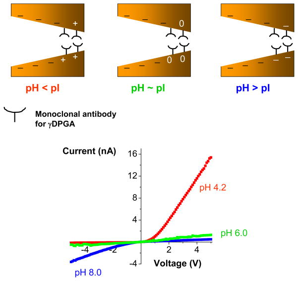
In order to develop a sensor for γDPGA, we first modified the tip of single conical pores with mAb F26G3. The tip area of a conical pore was first activated with S-NHS, and subsequently a solution of mAb F26G3 was added on both sides of the membrane. We expected that F26G3 would bind to the surface with one or several of its primary amines forming a peptide linkage to the surface. The resulted conical sensor containing at its tip the antibody, showed a very strong dependence of its current-voltage behavior on pH of the bulk solution (Fig. 9). At the basic pH of 8, the rectification direction was the same as for an unmodified pore, indicating that at these conditions F26G3 was negatively charged. Placing the system in an acidic pH resulted in a reversed rectification as well as in a significant increase of the rectification degree, providing evidence for the formation of a bipolar diode junction. We would also like to emphasize the huge increase of currents for positive voltages, which in turn suggested that the surface charge of mAb F26G3 at acidic pH is positive and very high. Indeed, the current magnitude for positive voltages suggests that at acidic pH, the effective surface charge density of F26G3 is close to the surface charge density of fully aminated PET pores thus σ ~ 1e/nm2; this surface charge density is enormously high for a protein. Such huge surface charge is rather overestimated because we ignored a probable decrease in the effective pore radius after binding of the antibody to the pore walls. The system does not rectify at pH~6, thus the determined pI of the surface immobilized antibody F26G3 is around 6. The rectification degree at pH = 4.2, calculated as I(−5V)/I(+5V) is less than 0.01, while at pH=8, Q~7. Such huge variation in the rectification degree should allow for an unambiguous detection of γDPGA upon its binding at the tip of the pore.
Figure 9.
Determination of isoelectric point of the monoclonal antibody for the bacterial polyglutamic acid (γDPGA). Current-voltage curves were recorded for a conical nanopore whose tip had been modified with a monoclonal antibody (F26G3) to the bacterial γDPGA. The measurements were performed in 10 mM KCl and at various pH values. At acidic pH conditions, the antibody F26G3 was positively charged (red recordings), while at basic pH it was negatively charged (blue recordings). The system stopped rectifying at pH ~6.0 (green recordings), which corresponded to pI of the antibody. The schemes show various surface charge patterns that were created at the three studied pH values. The uneven surface charge pattern was created at acidic pH values, which caused the formation of a strongly rectifying bipolar diode.
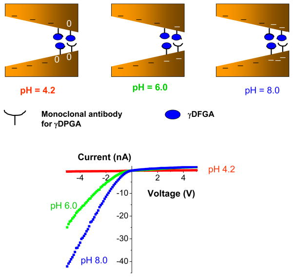
Pores whose tips were modified with mAb were incubated with the bacterial γDPGA and, after washing with KCl, the current-voltage curves were re-measured (Fig. 10). Carboxyl groups of γDPGA render this polypeptide heavily negatively charged for pH > 4, when the groups are deprotonated. Thus addition of anthrax polypeptide capsule to a conical nanochannel containing mAb F26G3 yields a system which rectifies ionic current only in one direction for all examined pH conditions (Fig. 10). pH values however change the magnitude of ion currents especially for negative voltages. For example at pH~8, when virtually all carboxyls are charged, the current at −5V exceeds 40nA. Such large currents can be induced only by very high effective surface charge densities at the tip, resulting from binding of γDPGA to the immobilized F26G3 antibody. Judging by the current magnitude, the negative surface charge at the tip of the final structure is much higher than that of an unmodified conical nanopore as well as of a BP diode formed by immobilization of mAb F26G3 (see Fig. 9). It should be noted that since γDPGA is a very large molecule, its parts might occupy the nanochannel interior and cause an effective “doping” of the nanochannel volume by potassium ions (counterions to the carboxyls). Thus referring to the nanochannel “surface charge” might not be appropriate for such large immobilized polymers.
Figure 10.
Sensing γDPGA with a nanopore that contained mAb F26G3 at the tip. A nanopore with mAb F26G3 was incubated with a solution of γDPGA for 3 hours, and the current voltage-voltage curves were measured in 10 mM KCl. Depending on pH of the solution, different surface charge patterns were formed on the pore walls (see the schematics in the upper part of the figure), which led to different current-voltage curves. At pH > 4, the polypeptide was negatively charged thus the current-voltage curves reversed compared to the situation before the γDPGA binding (see Fig. 9).
At acidic pH of ~ 4, on the other hand, the currents are very low down to 0.4 nA. Such low values of ion current at acidic conditions can be caused by the combination of two effects: i) protonation of the γDPGA’s carboxyls and ii) protonation of underlying F26G3 antibody. Both those effects might play a substantial role since pKa of carboxyl groups is ~4.2, and at pH~4.2, F26G3 changes its sign to positive (Fig. 9). Interestingly, a reversal of the current-voltage curve was not observed for the system with attached γDPGA (Fig. 10), which suggests that the electrostatic effect of mAb F26G3 is effectively shielded by the polypeptide located on top of the antibody. Such small currents (0.4nA) also support the hypothesis that the γDPGA molecules significantly extend to the nanochannel volume blocking the ion current flux.
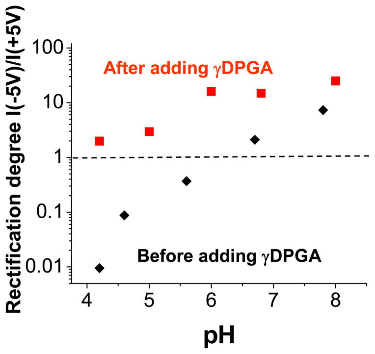
Figure 11 summarizes the experiments performed with the ionic diodes formed by attachment of mAb F26G3 and γDPGA. It can be clearly seen that the detection of γDPGA that bound to mAb at the tip of a conical pore produces the largest change in the rectification degree for pH < 6. It is because in these conditions, the antibody F26G3 is positively charged, while the polypeptide is still negative thus its binding to the pore tip produces a reversed current-voltage curve. For example, at pH 4.2, the ratio of rectification degrees before and after γDPGA exposure is more than 200 (Fig. 11).
Figure 11.
Sensing bacterial polyglutamic acid (γDPGA) with a nanofluidic diode – summary of Fig. 9 and Fig. 10. Rectification degree for 5V is shown as a function of pH. Dashed line (---) is a guide to the eye showing no rectification, i.e. Q = 1. Rectification direction at acidic pH for a nanopore modified with mAb F26G3 (■) is reversed compared to the rectification of the same pore after exposure to γDPGA (
 ). See text for details.
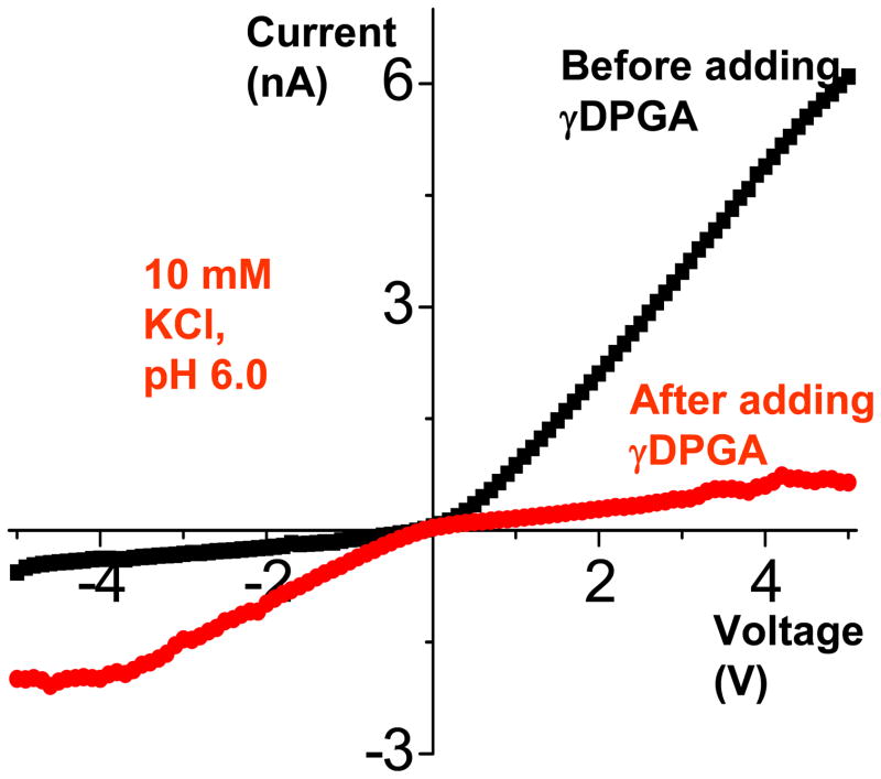
We also checked existence of non-specific adsorption of γDPGA to the pore walls. We expected that this effect would be mostly electrostatic in nature since a heavily negatively charged polypeptide will be electrostatically attracted to positively charged surfaces. We thus exposed a conical nanopore whose tip was modified with avidin to the same solution of γDPGA that was used in the previous sensing experiments. The current-voltage curves recorded before and after the addition of γDPGA are shown in Fig. 12. The non-specific adsorption is measurable, since the current-voltage curve reversed, as it was observed for nanopores modified with the antibody. The current values however, are more than an order of magnitude smaller than the currents obtained in a system containing mAb F26G3 (compare Fig. 9 and 10). We would also like to point that in our sensing experiments we used rather high polypeptide concentrations, thus the non-specific adsorption effect presented here reflects the “worst case scenario”.
Figure 12.
Studies of non-specific adsorption of γDPGA to nanopores with positively charged tip. A single nanopore was asymmetrically modified at the tip with avidin, and exposed to a solution containing γDPGA. Non-specific adsorption caused a flip of the current-voltage curve, however the recorded negative currents were significantly lower than the currents observed upon binding of γDPGA to a nanopore that contained mAb F26G3 (see Fig. 10). The measurements were performed in 10 mM KCl, pH 6.0.
Conclusions
We have described preparation of a specific biosensing platform based on conical nanofluidic diodes. A tip of the sensor was modified with a recognition agent for a specific analyte that was present in a solution. Binding of the analyte changed the surface charge pattern of the system, which was detected as the change in the current-voltage curves measured in a KCl solution. Thus we propose to use rectification degree as the main detection signal for a presence of an analyte. Placing the recognition agent only very locally at the tip of a conical nanopore has two main advantages. First, the amount of analyte that is needed to produce a measurable signal is smaller compared to a nanoporous system in which the entire pore walls are modified. Second, local binding of the analyte can produce uneven surface charge pattern, which can lead to preparation of ionic diodes. Ionic diodes are characterized by very high rectification degrees and a high sensitivity to local surface charge densities. The experiments have been supported by a theoretical modeling for an optimal geometry and surface charge pattern for the biosensor preparation.
The article presents biosensing systems for avidin, streptavidin, and the capsular polypeptide from B. anthracis. We also show that our system provides a new and label-free method for determination of isoelectric points of immobilized proteins. Isoelectric point of proteins on surfaces is known to differ from the corresponding values in a solution,45 and many other sensing techniques such as Enzyme-Linked Immunosorbent Assay (ELISA) rely on immobilized molecules. Knowledge of isolectric point of proteins can therefore improve other biosensing techniques.
Our future efforts will be focused on studying the detection limits offered by our biosensor as well as detection of proteins present in mixtures. We will also study how the sensing protocol can be applied for systems with various binding affinities. It will also be interesting to experimentally determine the position of the transition zone z0, thus the length of the pore that undergoes the chemical modification (see Fig. 1B). In order to visualize the modified pores, we plan to attach gold nanoparticles to the pore walls of a membrane containing many pores e.g. 108 pores/cm2. Cross-sections of these samples will tell us how far from the pore opening the reaction occurs.
Supplementary Material
Acknowledgments
This work was supported by the NIAID funded Pacific Southwest Regional Center of Excellence grant number AI-65359 through UC Irvine cost share funds (ZS). This study was also supported in part by the Pacific Southwest Regional Center for Excellence in Biodefense and Emerging Infections U54 AI065359 (ZSS and TRK), National Science Foundation grant CHE 0747237 (ZSS), and Public Health Service grant U01 AI065359 (T.R.K.). The single heavy ion irradiation was performed at the Gesellschaft fuer Schwerionenforschung, Darmstadt, Germany. We are grateful to Dr. Christina Trautmann for providing us with the irradiated polymer films.
Footnotes
Supporting Information Available: Studies of non-specific adsorption of streptavidin to 2-methoxyethylamine modified nanopore, and adsorption of the antibody F2G26 onto etched polyethylene terphthalate nanopores, as well as the Poisson-Nernst-Planck calculations of rectification degree for bipolar diodes as a function of the surface charge density, and position of the transition zone. This material is available free of charge via the Internet at http://pubs.acs.org
References
- 1.Hille B. Ionic Channels of Excitable Membranes. 2. Sinauer; Sunderland MA: 1992. [Google Scholar]
- 2.Storm AJ, Chen JH, Ling XS, Zandbergen HW, Dekker C. Nature Mater. 2003;2:537–540. doi: 10.1038/nmat941. [DOI] [PubMed] [Google Scholar]
- 3.Dekker C. Nature Nanotech. 2007;2:209–215. doi: 10.1038/nnano.2007.27. [DOI] [PubMed] [Google Scholar]
- 4.Li J, Stein D, McMullan C, Branton D, Aziz MJ, Golovchenko JA. Nature. 2001;412:166–169. doi: 10.1038/35084037. [DOI] [PubMed] [Google Scholar]
- 5.Cao H, Yu Z, Wang J, Tegenfeldt JO, Austin RH, Chen E, Wu W, Chou SY. Appl Phys Lett. 2002;81:174–176. [Google Scholar]
- 6.Xia Q, Morton KJ, Austin RH, Chou SY. Nano Lett. 2008;8:3830–3833. doi: 10.1021/nl802219b. [DOI] [PubMed] [Google Scholar]
- 7.Saleh OA, Sohn LL. Nano Lett. 2003;3:37–38. [Google Scholar]
- 8.Apel PY, Korchev YE, Siwy Z, Spohr R, Yoshida M. Nucl Instrum Methods Phys Res B. 2001;184:337–346. [Google Scholar]
- 9.Karhanek M, Kemp JT, Pourmand N, Davis RW, Webb CD. Nano Lett. 2005;5:403–407. doi: 10.1021/nl0480464. [DOI] [PubMed] [Google Scholar]
- 10.Zhang B, Zhang Y, White HS. Anal Chem. 2004;76:6229–6238. doi: 10.1021/ac049288r. [DOI] [PubMed] [Google Scholar]
- 11.(a) Vlassiouk I, Park CD, Vail SA, Gust D, Smirnov S. Nano Lett. 2006;6:1013–1017. doi: 10.1021/nl060313d. [DOI] [PMC free article] [PubMed] [Google Scholar]; (b) Wang G, Bohaty AK, Zharov I, White HS. J Am Chem Soc. 2006;128:13553–13558. doi: 10.1021/ja064274j. [DOI] [PubMed] [Google Scholar]
- 12.Lee SB, Martin CR. Anal Chem. 2001;73:768–775. doi: 10.1021/ac0008901. [DOI] [PubMed] [Google Scholar]
- 13.Karnik R, Castelino K, Fan R, Yang P, Majumdar A. Nano Lett. 2006;5:1638–1642. doi: 10.1021/nl050966e. [DOI] [PubMed] [Google Scholar]
- 14.Vlassiouk I, Takmakov P, Smirnov S. Langmuir. 2005;21:4776–4778. doi: 10.1021/la0471644. [DOI] [PubMed] [Google Scholar]
- 15.Gyurcsanyi RE. Trends in Analytical Chemistry. 2008;27:627–639. and references therein. [Google Scholar]
- 16.Uram JD, Ke K, Mayer M. ACS Nano. 2008;2:857–872. doi: 10.1021/nn700322m. [DOI] [PubMed] [Google Scholar]
- 17.Siwy Z, Trofin L, Kohli P, Baker LA, Trautmann C, Martin CR. J Am Chem Soc. 2005;127:5000–5001. doi: 10.1021/ja043910f. [DOI] [PubMed] [Google Scholar]
- 18.Stein D, Kruithof M, Dekker C. Phys Rev Lett. 2004;93(1–4):035901. doi: 10.1103/PhysRevLett.93.035901. [DOI] [PubMed] [Google Scholar]
- 19.Jágerszki G, Gyurcsanyi RE, Höfler L, Pretsch E. Nano Lett. 2007;7:1609–1612. doi: 10.1021/nl0705438. [DOI] [PMC free article] [PubMed] [Google Scholar]
- 20.Ali M, Bayer V, Schiedt B, Neumann R, Ensinger W. Nanotechnology. 2008;19(1–9):485711. doi: 10.1088/0957-4484/19/48/485711. [DOI] [PubMed] [Google Scholar]
- 21.Vlassiouk I, Smirnov S, Siwy Z. Nano Lett. 2008;8:1978–1985. doi: 10.1021/nl800949k. [DOI] [PubMed] [Google Scholar]
- 22.DeBlois RW, Bean CP. Rev Sci Instrum. 1970;41:909–915. [Google Scholar]
- 23.Saleh OA, Sohn LL. Proc Nat Acad Sci USA. 2003;100:820–824. doi: 10.1073/pnas.0337563100. [DOI] [PMC free article] [PubMed] [Google Scholar]
- 24.Henriquez RR, Ito T, Sun L, Crooks RM. Analyst. 2004;129:478–482. doi: 10.1039/b404251b. [DOI] [PubMed] [Google Scholar]
- 25.Bayley H, Martin CR. Chem Rev. 2000;100:2575–2594. doi: 10.1021/cr980099g. [DOI] [PubMed] [Google Scholar]
- 26.Vlassiouk I, Siwy ZS. Nano Lett. 2007;7:552–556. doi: 10.1021/nl062924b. [DOI] [PubMed] [Google Scholar]
- 27.Kozel TR, Murphy WJ, Brandt S, Blazar B, Lovchik JA, Thorkildson P, Percival A, Lyons CR. Proc Natl Acad Sci USA. 2004;101:5042–5047. doi: 10.1073/pnas.0401351101. [DOI] [PMC free article] [PubMed] [Google Scholar]
- 28.(a) (b) Wolf A, Reber N, Ape1 P, Yu, Fischer BE, Spohr R. Nucl Instrum Methods Phys Res B. 1995;105:291–293. [Google Scholar]; (b) Wolf-Reber A. PhD dissertation. 2002. Aufbau eines Rasterionenleitwertmikroskops. Stromfluktuationen in Nanoporen. dissertation. de. [Google Scholar]
- 29.Grabarek Z, Gergely J. Anal Biochem. 1990;185:131–135. doi: 10.1016/0003-2697(90)90267-d. [DOI] [PubMed] [Google Scholar]
- 30.Vlassiouk I, Smirnov S, Siwy Z. ACS Nano. 2008;2:1589–1602. doi: 10.1021/nn800306u. [DOI] [PubMed] [Google Scholar]
- 31.Wei C, Bard AJ, Feldberg SW. Anal Chem. 1997;69:4627–4633. [Google Scholar]
- 32.White HS, Bund A. Langmuir. 2008;24:2212–2218. doi: 10.1021/la702955k. [DOI] [PubMed] [Google Scholar]
- 33.Siwy ZS. Adv Funct Mater. 2006;16:735–746. [Google Scholar]
- 34.Cervera J, Schiedt B, Ramirez P. Europhys Lett. 2005;71:35–41. [Google Scholar]
- 35.Cervera J, Schiedt B, Neumann R, Mafe S, Ramirez P. J Chem Phys. 2006;124(1–9):104706. doi: 10.1063/1.2179797. [DOI] [PubMed] [Google Scholar]
- 36.Kosinska ID, Goychuk I, Kostur M, Schmid G, Hanggi P. Phys Rev E. 2008;77(1–10):031131. doi: 10.1103/PhysRevE.77.031131. [DOI] [PubMed] [Google Scholar]
- 37.Siwy Z, Heins E, Harrell CC, Kohli P, Martin CR. J Am Chem Soc. 2004;126:10850–10851. doi: 10.1021/ja047675c. [DOI] [PubMed] [Google Scholar]
- 38.Ali M, Yameen B, Neumann R, Ensinger W, Knoll W, Azzaroni O. J Am Chem Soc. 2008;130:16351–16357. doi: 10.1021/ja8071258. [DOI] [PubMed] [Google Scholar]
- 39.Ramirez P, Apel P, Yu, Cervera J, Mafe S. Nanotechnology. 2008;19(1–12):315707. doi: 10.1088/0957-4484/19/31/315707. [DOI] [PubMed] [Google Scholar]
- 40.Daiguji H, Oka Y, Shirono K. Nano Lett. 2005;5:2274–2280. doi: 10.1021/nl051646y. [DOI] [PubMed] [Google Scholar]
- 41.Karnik R, Duan C, Castelino K, Daiguji H, Majumdar A. Nano Lett. 2007;7:547–551. doi: 10.1021/nl062806o. [DOI] [PubMed] [Google Scholar]
- 42.Ali M, Schiedt B, Healy K, Neumann R, Ensinger W. Nanotechnology. 2008;19(1–6):085713. doi: 10.1088/0957-4484/19/8/085713. [DOI] [PubMed] [Google Scholar]
- 43.Green NM. Advances in Protein Chemistry. 1975;29:85–133. doi: 10.1016/s0065-3233(08)60411-8. [DOI] [PubMed] [Google Scholar]
- 44.Spinke J, Liley M, Schmitt FJ, Guder HJ, Angermaier L, Knoll W. J Chem Phys. 1993;99:7012–7019. [Google Scholar]
- 45.Sivasankar S, Subramaniam S, Leckband D. Proc Natl Acad Sci USA. 1998;95:12961–12966. doi: 10.1073/pnas.95.22.12961. [DOI] [PMC free article] [PubMed] [Google Scholar]
Associated Data
This section collects any data citations, data availability statements, or supplementary materials included in this article.


