Abstract
Purpose: Data sufficiency are a major problem in four-dimensional cone-beam computed tomography (4D-CBCT) on linear accelerator-integrated scanners for image-guided radiotherapy. Scan times must be in the range of 4–6 min to avoid undersampling artifacts. Various image reconstruction algorithms have been proposed to accommodate undersampled data acquisitions, but these algorithms are computationally expensive, may require long reconstruction times, and may require algorithm parameters to be optimized. The authors present a novel reconstruction method, 4D volume-of-interest (4D-VOI) reconstruction which suppresses undersampling artifacts and resolves lung tumor motion for undersampled 1-min scans. The 4D-VOI reconstruction is much less computationally expensive than other 4D-CBCT algorithms.
Methods: The 4D-VOI method uses respiration-correlated projection data to reconstruct a four-dimensional (4D) image inside a VOI containing the moving tumor, and uncorrelated projection data to reconstruct a three-dimensional (3D) image outside the VOI. Anatomical motion is resolved inside the VOI and blurred outside the VOI. The authors acquired a 1-min. scan of an anthropomorphic chest phantom containing a moving water-filled sphere. The authors also used previously acquired 1-min scans for two lung cancer patients who had received CBCT-guided radiation therapy. The same raw data were used to test and compare the 4D-VOI reconstruction with the standard 4D reconstruction and the McKinnon-Bates (MB) reconstruction algorithms.
Results: Both the 4D-VOI and the MB reconstructions suppress nearly all the streak artifacts compared with the standard 4D reconstruction, but the 4D-VOI has 3–8 times greater contrast-to-noise ratio than the MB reconstruction. In the dynamic chest phantom study, the 4D-VOI and the standard 4D reconstructions both resolved a moving sphere with an 18 mm displacement. The 4D-VOI reconstruction shows a motion blur of only 3 mm, whereas the MB reconstruction shows a motion blur of 13 mm. With graphics processing unit hardware used to accelerate computations, the 4D-VOI reconstruction required a 40-s reconstruction time.
Conclusions: 4D-VOI reconstruction effectively reduces undersampling artifacts and resolves lung tumor motion in 4D-CBCT. The 4D-VOI reconstruction is computationally inexpensive compared with more sophisticated iterative algorithms. Compared with these algorithms, our 4D-VOI reconstruction is an attractive alternative in 4D-CBCT for reconstructing target motion without generating numerous streak artifacts.
Keywords: volume-of-interest, image reconstruction, 4D-CBCT, image-guided radiation therapy
INTRODUCTION
The use of imaging to guide radiation therapy procedures, i.e., image-guided radiation therapy (IGRT), has become standard practice. Flat panel kilovoltage imaging systems integrated with medical linear accelerators acquire patient images at treatment time. The imaging system is integrated into the linac gantry and can acquire x-ray projection data over a continuous rotation for cone-beam computed tomography (CBCT) imaging.1, 2 CT imaging shows greater soft tissue contrast than x-ray projection imaging. The three-dimensional (3D) position of soft tissue structures can be verified with CBCT to more accurately localize the target.2, 3, 4, 5, 6, 7, 8 In radiation therapy, it is critical to accurately locate the target lesions and the normal organs that are at risk. To account for any uncertainties in target position, safety margins are usually added to target volumes in treatment planning to ensure complete coverage.9 However, safety margins also cause more healthy tissue to be irradiated. Grills et al. found that the margins needed for setup uncertainty were 9–13 mm without CBCT guidance and 2–4 mm with CBCT guidance.6 Therefore, a clear advantage exists for using CBCT image guidance.
Because of slow gantry rotation (1 rotation/min maximum), linac-integrated CBCT has a low temporal resolution. Patient movement results in a motion blur, which corresponds with an uncertainty in the target location.10 In many radiotherapy procedures, this concern is addressed by immobilizing the patient and using safety margins. In radiation therapy for lung cancer, it may be impossible to completely immobilize the target lesion because the lung expands and contracts during respiration, and breath-hold techniques are often unfeasible.
4D-CBCT was developed to address the lack of temporal resolution in linac-integrated CBCT.10, 11, 12, 13, 14 In this method, the raw cone-beam projections are time-stamped, and a synchronized signal of the patient’s respiration is also acquired. Using the projection data’s time stamp and the synchronized breathing signal (e.g., chest wall or abdominal expansion), each cone-beam projection is assigned to a specific phase of the breathing cycle, and then the image is reconstructed in 4D (i.e., with respiratory phase as the fourth dimension.) Typically, the Feldkamp filtered backprojection reconstruction algorithm15 is applied on the sorted projection data. 4D-CBCT has been used to improve localization accuracy in radiation therapy and to assess position uncertainties due to both interfractional and intrafractional motion.16, 17, 18 Data sufficiency are a fundamental issue in tomographic image reconstruction. If each phase subset does not have a sufficient number of projections for all projection angle intervals, the image reconstruction becomes inaccurate and degraded by artifacts. Scan times of about 4–6 min have been used in 4D-CBCT for low undersampling artifacts.10, 11, 12, 13, 14 Unfortunately, such scan times may be too long and impractical in the context of a radiotherapy session, for which a typical treatment session time is approximately 15 min, depending on the specific procedure and institution. The challenge, therefore, is to make use of a shorter scan time which necessarily provides an undersampled projection dataset. To date, no routine clinical 4D-CBCT protocols in IGRT have been developed to use a 1-min acquisition, which is known to be prone to numerous streak artifacts upon standard reconstruction.19
Various reconstruction algorithms have been proposed to address sparse-view sampling in CBCT and 4D-CBCT. One approach is to incorporate all data, rather than just the binned subset, into the reconstruction. This approach is taken in the autoadaptive phase-correlated (AAPC) (Ref. 20) and McKinnon-Bates (MB) (Refs. 21, 22) reconstruction algorithms. Both algorithms are able to reduce the undersampling artifacts, but each has certain disadvantages. The AAPC reconstruction requires an algorithm for segmenting detector pixels into two groups: pixels affected and unaffected by motion. This segmentation requires parameters that may need to be optimized. The MB algorithm can eliminate streak artifacts22 but shows increased noise and also introduces other artifacts. Furthermore, the temporal resolution of the MB algorithm may not be as good as that in the standard 4D algorithm.23 There are also iterative algorithms for image reconstruction with sparse projection data. CBCT image reconstruction using a very few samples has been demonstrated through total-variation minimization.24, 25 Prior image constrained compressed sensing (PICCS), uses a prior image constraint to improve the reconstruction accuracy and convergence speed.26, 27 Evaluations of the image quality, robustness, convergence, and computational aspects of these iterative reconstruction algorithms using sparse data were provided by Bergner et al.23 and Bian et al.28 The iterative reconstruction algorithms referenced above are very promising for sparse-view reconstructions, but the prohibitive factor may be the computational cost. In IGRT, the image should be available immediately after acquisition. Pan et al. outlined several reasons (applicability, implementation challenges, and computational cost) describing why none of these iterative algorithms have been used in the clinical CT scanning systems.29
We present here a novel method in image reconstruction for 4D-CBCT. The purpose of our reconstruction method, which we call 4D volume-of-interest (4D-VOI) reconstruction, is to reconstruct 4D-CBCT images from undersampled data acquisitions of about 1-min scan time. The objective is to achieve higher image quality than in other analytical reconstruction algorithms, while keeping computational cost much lower than that of iterative reconstruction algorithms. The computational cost must be sufficiently low that a practical computational implementation is feasible for IGRT. The improved image quality, short scan time, and practical computational cost would be important improvements in 4D-CBCT for IGRT.
METHODS
4D-VOI reconstruction
In our 4D-VOI reconstruction, we first perform a 3D (motion averaged) reconstruction using all (i.e., unsorted) projection data. The 3D reconstruction is performed using the Feldkamp reconstruction which is given by the following discrete formula:
where M is the total number of projections, Q(β,t,u) is the filtered raw cone-beam projection data, and U is a weighting factor in backprojection. The Cartesian coordinates (x,y,z) represent the reconstruction volume, and the coordinates (β,t,u) represent the raw data (sinogram) space. The coordinate β is the projection angle, and (t,u) are the horizontal and vertical distances on a flat panel detector, respectively. These factors are explained in greater detail by Feldkamp et al.15 The backprojection is performed with the summation. In the conventional 4D-CBCT (full 4D) reconstruction, the projections [1,M] are sorted into phase bins (B1, B2, …, BN), where N is the number of respiratory phases to be reconstructed. The full 4D reconstruction is given by
where k: {1,N} is the respiration phase to be reconstructed, and n(Bk) is the number of projections in the kth respiration phase. The major difference between the full 4D reconstruction and the 3D reconstruction is that the summation runs over a more limited set of projections in the full 4D case.
In our 4D-VOI reconstruction, we use the 3D reconstruction to define a 3D volume-of-interest (VOI) that contains the radiotherapy target, including any respiratory motion. This VOI may be a user-drawn contour or a generic shape such as a cube, cylinder, or sphere. We define the 4D-VOI reconstruction as a composite of the 3D and full 4D reconstructions,
In other words, the region inside the VOI is set equal to the full 4D reconstruction, and the area outside of the VOI is set equal to the 3D reconstruction. The purpose of this composite reconstruction is to eliminate the streak artifacts outside the VOI, where temporal resolution is not needed. The temporal resolution is maintained within the VOI, where we want to see the tumor motion.
In patient studies, an appropriate VOI for our reconstruction method is not necessarily known. For these patient studies, we used the planned target volume (PTV) from radiation therapy planning as the choice of VOI in our reconstruction. The PTV is a volume based on a contour drawn by a physician on a treatment planning image (typically CT). The PTV delineates the radiation therapy target and also contains safety margins to account for many sources of uncertainty in target position and size caused by respiratory motion, setup errors, unseen microscopic, and diseased tissue.9 The PTV is a priori information based on a physician’s interpretation of CT images, and it includes margins for target position uncertainty. We believe it is a reliable choice of VOI for our reconstruction as it is specifically designed to contain the target. The workflow for the 4D-VOI reconstruction was as follows. First, the unsorted raw CBCT was used to reconstruct the motion averaged (3D-CBCT) image. Next, the PTV from the treatment plan was registered to the 3D-CBCT image. The PTV was manually registered to the 3D-CBCT image using a rigid body translation. Having placed the PTV, the final step was to perform the 4D reconstruction for the voxels inside the PTV. We sorted the projection data using the respiration signal. The sorted projection data are used for 4D reconstruction in only the VOI region.
The 4D-VOI reconstruction is computationally practical from a clinical perspective since it uses Feldkamp reconstruction. We implemented the 4D-VOI reconstruction using a graphics processing unit (Refs. 30, 31, 32, 33) and measured a computation time of 40 s. Iterative algorithms proposed for 4D-CBCT have not been shown to have clinically practical computation times.
Mathematical phantom study
A mathematical phantom was used to test our VOI-based reconstruction. Our reconstruction is designed for cone-beam CT but is also applicable to any projection imaging system where large gaps in angular sampling may occur. For simplicity, we performed a simulation using a two-dimensional phantom with motion, based on the commonly used Shepp–Logan phantom.34 The phantom is composed of ellipses, whose parameters are listed in Ref. 30. We replaced the three small (high-contrast detectability) ellipses with a moving circular disk as shown in Fig. 1. The disk has a continuous sinusoidal motion with a 4-s period, and the motion amplitude is equal to the diameter of the disk. The ellipse parameters defining the moving disk are provided in Table TABLE I.. We simulated noiseless x-ray projection data with a slow gantry completing a half-rotation with a 1-min scan time. The projection data were then sorted into eight phase bins. The parameters for this simulated scan are provided in Table TABLE II.. This combination of motion period, gantry rotation time, and projection sorting resulted in a distribution of projection angles that is representative of 1-min 4D-CBCT. The mathematical phantom is useful because it contains high intensity structures that generate streak artifacts when there is angular undersampling.
Figure 1.
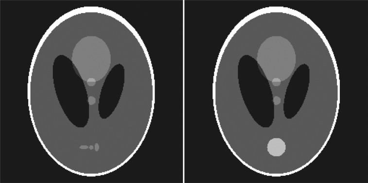
Left—Commonly used Shepp–Logan phantom. Right—Modified motion phantom. The three detail spheres near the bottom have been replaced with a circular disk that moves in the vertical direction
TABLE I.
Parameters defining the moving disk in the Shepp–Logan phantom.
| Center coordinate [x(t), y(t)] | [0.1*sin(2π t/4 s), 0] |
|---|---|
| Major axis length (x-direction) | 0.1 |
| Minor axis length (y-direction) | 0.1 |
| Intensity | 0.25 |
TABLE II.
Simulation scan parameters.
| Phantom size | 256 × 256 |
| Number of detectors | 512 |
| Fan angle | 15.09° |
| Scan range | 0°–195.09° |
| Number of projection angles | 660 |
| Scan time | 60 s |
| Number of phase bins | 8 |
Dynamic chest phantom study
A dynamic chest phantom was setup to simulate a lung tumor undergoing respiratory motion. An anthropomorphic chest phantom was used so that the realistic streak artifacts would be generated in undersampled acquisitions. The chest cavity of the phantom was emptied, and a 2-cm-diameter water-filled sphere was placed in the emptied volume of the left lung. This sphere was suspended in the lung by a moveable plastic rod that was driven by a motor to simulate the periodic respiratory motion. The water-filled sphere was programmed to move in the superior–inferior direction with a 1.8-cm amplitude and a 4.2-s period. The phantom was scanned with the Varian On-Board Imager (OBI) CBCT scanner (Varian Medical Systems, Palo Alto, CA) in its clinical low-dose thorax mode. This mode completes one gantry rotation in 60 s and acquires 660 projections over a 360-deg rotation. We used the known motion profile to sort out the projections into eight respiratory phase bins.
Patient studies
We performed retrospective 4D-CBCT patient studies using data from lung cancer patients who had received stereotactic body radiation therapy. We used the raw CBCT data and the respiratory tracking data from two patient studies. The respiration tracking method used the Varian Real-time Position Management (RPM) System to track the height of the chest wall of a free-breathing patient lying in the supine position.35 The two patients had long acquisition (4.5–6 min) 4D-CBCT scans.14 Since the purpose of our present study was to demonstrate 4D-CBCT with short acquisitions of about 1 min, we reduced the number of projections of the long acquisitions. The projections were removed in a way that represented an accurate number of breath cycles for a 1-min scan time. For instance, to reduce the scan time by 80%, the projection data for only one of five breath cycles were retained, while data for the other four breath cycles were discarded. This process produced an angular distribution of projection angles that was a realistic representation of a 1-min scan. After reducing the datasets to 1-min, we had 403 and 406 projections for patients 1 and 2, respectively.
Image quality comparison of 4D-VOI and reference reconstruction algorithms
The 4D-VOI, standard 4D, and MB algorithms were tested and compared using the same acquisition data. For both phantom and patient studies, the 4D-VOI reconstruction was compared with the standard phase-sorted Feldkamp reconstruction in terms of image quality. Because the entire volume in the standard phase-correlated Feldkamp reconstruction was 4D (whereas our reconstruction had only a small 4D volume), we referred to the former as the “full 4D” reconstruction. We assessed in particular the streak artifacts that resulted from undersampling. We also compared 4D-VOI with the MB reconstruction algorithm in terms of streak artifacts and image contrast. Last, the standard 3D reconstruction was also included as a reference point for assessing the temporal resolution gained in the 4D methods.
To highlight and assess the streak artifacts in the different reconstructions, we also processed each image with a Sobel 3 × 3 pixel edge-detection kernel. This is the default edge-detection filter in the ImageJ viewer and processing software.36 The edge-detection filter brings out straight edges (streak artifacts) and also the inherent edges of the object.
We also assessed the motion resolution in the phantom study because we know the actual motion. The motion blur was quantitatively assessed by measuring the apparent width of the sphere. We measured the image intensity along a line profile through the moving sphere at both the end-inhale and the end-exhale phases. The motion blurring was then quantitatively assessed by measuring the apparent width of the sphere. The sphere size was measured as the full-width half-maximum (FWHM) of the peak seen in the line profile. The motion displacement is measured as the displacement of the peak (as determined by FWHM) between the end-exhale and the end-inhale phases.
Last, we measured the contrast-to-noise ratio (CNR) for the different reconstructions. In the patient studies, we measured the mean image intensity values in a homogeneous region in the heart and in a region in the background lung. This was divided by the noise (standard deviation) of the region of interest in the heart. In the phantom, we had a similar measurement, except that we used a region in the water instead of in the heart.
RESULTS
Mathematical phantom
The mathematical phantom is a two-dimensional moving object. To avoid confusion with the terms “2D,” “3D,” and “4D,” we use the following names for the reconstructions in this mathematical phantom study: “Dynamic ROI reconstruction” refers to the reconstruction in which motion is resolved in a small region only. It is analogous to our 4D-VOI reconstruction in CBCT. “Full dynamic” refers to the reconstruction in which motion is resolved throughout the imaging volume. It is analogous to full 4D reconstruction in CBCT. “Motion averaged” refers to the reconstruction using the complete, unsorted projection data set. It is analogous to 3D reconstruction in CBCT. The names are summarized in Table TABLE III..
TABLE III.
Names adopted for the reconstructions in the mathematical phantom study.
| Mathematical phantom study | Analogous CBCT reconstruction |
|---|---|
| Dynamic ROI | 4D-VOI |
| Full dynamic | Full 4D |
| Motion averaged | 3D-CBCT |
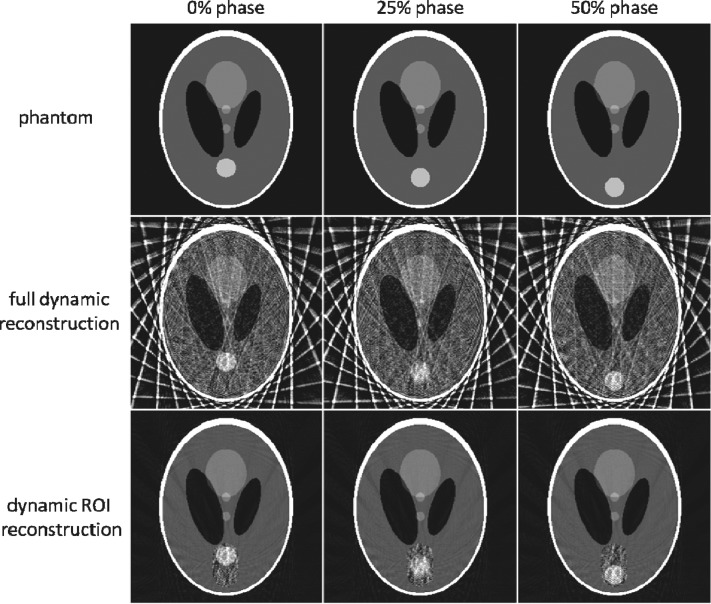
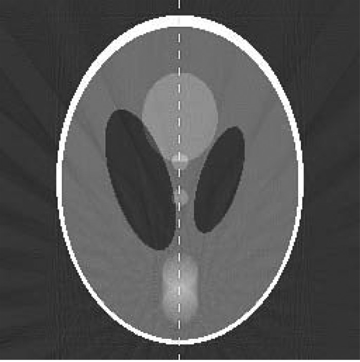
The reconstructed images for dynamic ROI, full dynamic, and motion averaged reconstructions are shown in Fig. 2. Undersampling produces severe streak artifacts in the full dynamic reconstruction. The ROI selected for the dynamic ROI reconstruction is shown by the dotted line in Fig. 3. Although there is no improvement inside the ROI in the dynamic ROI reconstruction, there region outside the ROI is much improved due to the reduction of streak artifacts. The two low-contrast circles in the center of the phantom are far clearer in the dynamic ROI reconstruction. The motion averaged image reconstruction using all the projections (shown in Fig. 3) lacks temporal resolution and shows a motion blur for the moving disk.
Figure 2.
Dynamic ROI reconstruction compared against the full dynamic reconstruction and the truth image.
Figure 3.
Motion averaged reconstruction using all projection data. The dashed vertical line is used to measure the intensity line profile. The dotted line indicates the ROI used in the dynamic ROI reconstruction.
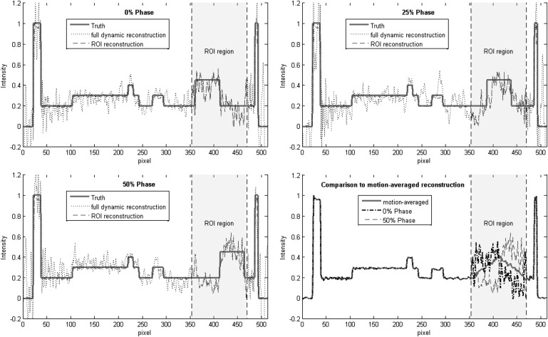
The quantitative accuracy of the dynamic ROI reconstruction was assessed using the line profile depicted by the dashed line in Fig. 3. The measured line profiles are shown in Fig. 4. The top left panel compares the dynamic ROI (dashed line) and full dynamic (dotted line) reconstructions at the 0% phase. The ground truth is shown in the solid red line. Outside the ROI region, the line profile for the full dynamic reconstruction shows large errors (root mean square error of about 0.25), whereas the line profile for the dynamic ROI reconstruction is essentially equivalent to the ground truth. Inside the ROI region, the line profiles for the dynamic ROI and full dynamic reconstructions are equivalent (by definition). The top right and bottom left panels of Fig. 4 show similar plots for the 25% and 50% phases. The bottom left panel compares the dynamic ROI reconstruction (0% and 50% phases) to the motion averaged reconstruction. The dynamic ROI reconstruction shows motion-resolved line profiles, whereas the motion averaged reconstruction shows a static triangular profile.
Figure 4.
Line profiles used to assess reconstruction accuracy of the dynamic ROI and full dynamic reconstructions. Top left—reconstruction of the 0% motion phase. Top right—25% motion phase. Bottom left—50% motion phase. Bottom right—Comparison of the dynamic ROI reconstruction to the motion averaged reconstruction.
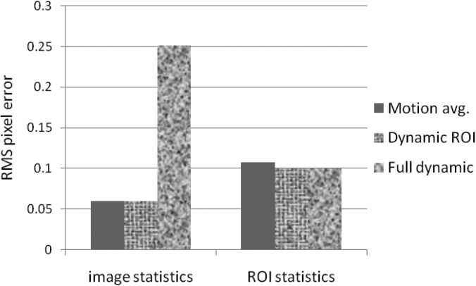
We measured the RMS pixel errors for the entire image and also for the ROI region only. The RMS errors of the various reconstructions are shown in Fig. 5. The RMS pixel statistics were calculated over (1) the entire image, and (2) only the ROI region. The full dynamic reconstruction has a large RMS error (0.25) over the whole image due to streak artifacts. Because of motion blur, the motion averaged reconstruction has slightly greater error inside the ROI (0.107) than the dynamic ROI and fully dynamic reconstructions (0.099 and 0.99 errors, respectively). The high contrast of the disk helps the dynamic ROI reconstruction to resolve the shape and the location of the disk, despite the presence of streak artifacts inside the ROI region. This result suggests that this reconstruction method may be advantageous for lung lesions, which typically have good contrast against the low density lung tissue background.
Figure 5.
RMS pixel error values for the motion averaged, dynamic ROI, and full dynamic reconstructions. The dynamic ROI and full dynamic reconstructions were reconstructed at the 0% motion phase.
Dynamic chest phantom
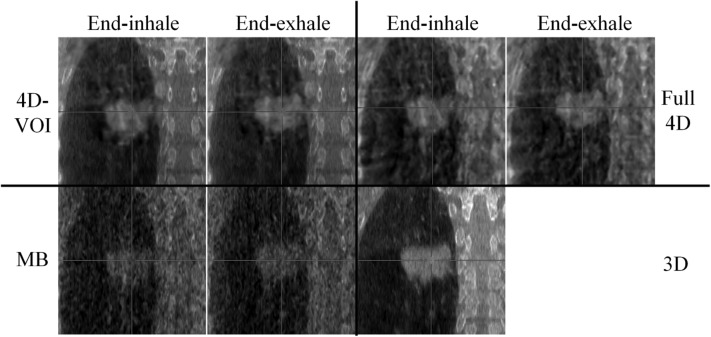
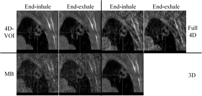
We compared the 4D-VOI, full 4D, and MB reconstructions in the dynamic chest phantom experiment. The reconstructed images are shown in Figs. 67. For the coronal views in Fig. 6, the two extreme phases (end-exhale and end-inhale) are shown. In the 4D-VOI reconstruction, the VOI is a tight cylinder enclosing the moving sphere. The 4D-VOI reconstruction shows a clear motion of 2 cm, as measured by a simple distance-measuring tool on an image viewer. The full 4D reconstruction also shows the same motion since, by definition, it has the same values inside the VOI as the 4D-VOI.
Figure 6.
Phantom study: a 2-cm-diameter sphere moving inside an empty chest cavity phantom with 1.8-cm motion amplitude. Coronal views at end-inhale and end-exhale phases for the 4D-VOI, full 4D, MB, and static (3D) reconstructions. Window/level: 600/-20.
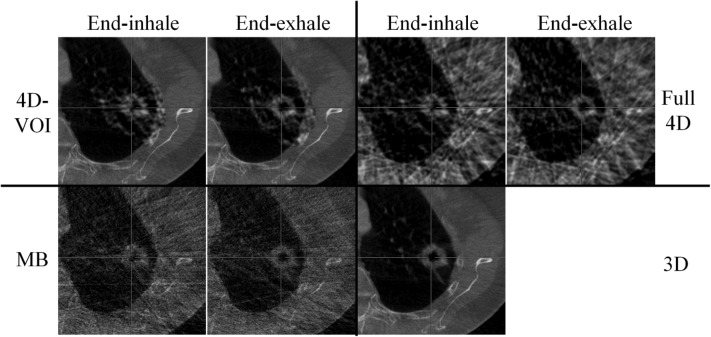
Figure 7.
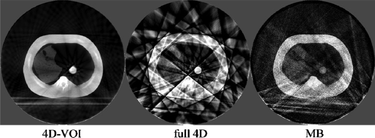
Phantom study: Axial views of the end-exhale phase. W/L: 600/-20.
The major difference between the 4D-VOI and the full 4D reconstructions is seen in the region outside the VOI where the full 4D images are distorted by streak artifacts. In the left side of the coronal images, the right lung material is visible. In the 4D-VOI reconstruction, the fine details of the porous lung material are visible compared with the full 4D reconstruction, which shows heavy streak artifacts. In the coronal view, the streak artifacts appear as alternating bright and dark vertical bands, and the lung material is highly distorted. The location of the chest wall interface is also ambiguous in the full 4D reconstruction. The rib cage is also prominently distorted as streaks radiate from these bones. The axial view in Fig. 7 shows the streak artifacts radiating from bony anatomy. The table on which the phantom rested is completely missing because of missing view angles of parallel rays through the table.
The MB reconstruction shows markedly fewer streak artifacts than the full 4D images. The location of the chest wall is clear, and some more details (such as air pockets in the lung material) are visible. The contrast was lost between the rib tissue and the soft tissue, so the position of the ribs is unclear. Unlike in the full 4D image, the table is visible, but it is distorted by streak artifacts. The MB reconstruction also shows poor temporal resolution, and motion blur is evident. Motion blur is discussed further in Sec. 3C.
To demonstrate the different amount of streak artifacts in the different reconstructions, we processed the images with the Sobel edge enhancement filter (Fig. 8). The streak artifacts appear as straight bright lines. It is clear that the 4D-VOI has the least amount of streak artifact, followed by the MB reconstruction. The noise increases in the MB reconstruction is apparent in this image. The numerous streak artifacts in the full 4D reconstructions are greatly intensified in the edge-filtered image.
Figure 8.
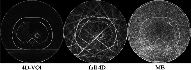
Phantom study: edge-detection filter processing on the 4D-VOI, full 4D, and MB reconstructions.
The CNR for the 4D-VOI method (11.4) is better than that for the other methods because of the lack of streak and other artifacts that increase measured noise. The full 4D reconstruction has a slightly higher CNR (2.2) than the MB reconstruction (1.5). CNR in the MB reconstruction was degraded because of an increase in noise and texture artifacts.
Motion assessment in phantom study
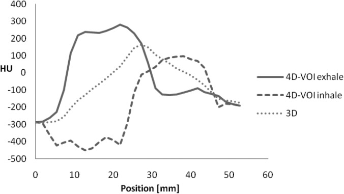
We assessed the sphere motion in the 4D-VOI reconstruction in the chest phantom study. Since the VOI regions are, by definition, identical in the 4D-VOI and full 4D reconstruction, the following measurements apply to both reconstructions. A line profile was taken through the VOI in the direction of object motion (Fig. 9). The true size of the sphere was 20 mm, but since the line profile was taken away from the center of the sphere, the ideal line profile width was 17 mm. The line profiles for the end-inhale and the end-exhale phase images in the 4D-VOI reconstruction are shown in Fig. 10, and the line profiles for the MB reconstruction are shown in Fig. 11. In the profiles for the 4D-VOI reconstruction, the sphere has a sharp edge and the movement of the sphere from the end-exhale to the end-inhale phases is apparent. The size of the sphere was 19.8 and 19.9 mm for the end-exhale and the end-inhale phase images, respectively, whereas the true size is 17 mm. This negligible amount of blurring may be expected from partial volume averaging (slice thickness is 2.5 mm), or even by how we define the measurement (for instance, full-width half-maximum instead of full-width tenth maximum.) The measured motion displacement was 17 mm, which is very close to the actual value of 18-mm. We conclude that any motion blur or loss of spatial resolution introduced by the 4D-VOI and the full-4D reconstructions is negligible. Last, we also observed a mean intensity shift of about 100 HU between the end-exhale and the end-inhale phases. This is due to residual streak artifact inside the VOI that could not be eliminated by our 4D-VOI method. Nevertheless, for the purpose of localization, the sphere location and the trajectory were sufficiently clear.
Figure 9.

Line profile used to assess motion resolution.
Figure 10.
Line profiles for the 4D-VOI reconstruction at end-exhale and end-inhale phases. Line profile for 3D reconstruction is also shown.
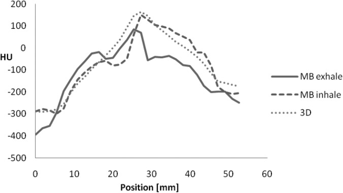
Figure 11.
Line profiles for the MB reconstruction at end-exhale and end-inhale phases. Line profile for 3D reconstruction is also shown.
On the other hand, the MB reconstruction algorithm showed a large motion blur for the sphere (Fig. 11). The size of the sphere was 29.1 and 29.9 mm the end-exhale and the end-inhale phase images, respectively, whereas the true size is 17 mm. This indicates a motion blur of about 12.5 mm. The line profiles also showed only a 3-mm sphere displacement between the two phases (actual displacement was 18 mm). We conclude that the sphere size, edge, and motion are not accurate in the MB reconstruction for this chest phantom study.
Patient studies
The 4D image sets for the two patient studies are shown in Figs. 121314151617–18. Because of increased noise in the VOI region, there is an obvious visual discontinuity at the boundary of the VOI. To equalize the noise with that of the background, the VOI region was smoothed with a 2D Gaussian filter of 1.5 voxel width (0.73 mm). For a fair comparison between the 4D-VOI and full 4D reconstructions, we applied the same Gaussian filtering after reconstruction to smooth the full 4D reconstruction.
Figure 12.
Patient 1, axial views for the 4D-VOI, full 4D, MB, and 3D reconstructions. Zoomed-in view of tumor. Top left: 4D-VOI, top right: Full 4D, bottom left: MB, bottom right: 3D. Image size: 13 cm. Window/level: 500/0.
Figure 13.
Patient 1, coronal views for the 4D-VOI, full 4D, MB, and 3D reconstructions. The tumor moves 1.5 cm in the superior–inferior direction. Top left: 4D-VOI, top right: Full 4D, bottom left: MB, bottom right: 3D. Zoomed-in view of tumor. Image size: 13 cm. Window/level: 500/0.
Figure 14.
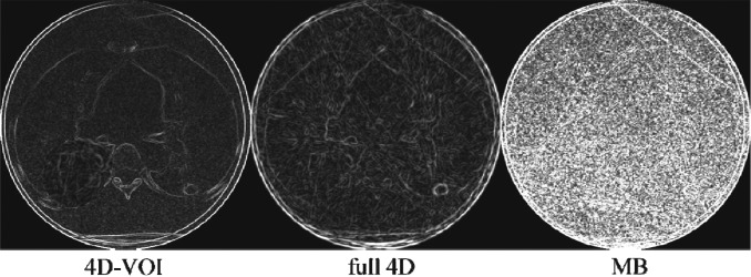
Patient 1, edge-detection filter processing on the 4D-VOI, full 4D, and MB reconstructions.
Figure 15.
Patient 2, axial views for the 4D-VOI, full 4D, MB, and 3D reconstructions. Zoomed-in view of tumor. Top left: 4D-VOI, top right: Full 4D, bottom left: MB, bottom right: 3D. Image size: 13 cm. Window/level: 500/0.
Figure 16.
Patient 2, coronal views for the 4D-VOI, full 4D, MB, and 3D reconstructions. The tumor moves 3 mm in the anterior–posterior direction. Zoomed-in view of tumor. Top left: 4D-VOI, top right: Full 4D, bottom left: MB, bottom right: 3D. Image size: 13 cm. Window/level: 500/0.
Figure 17.
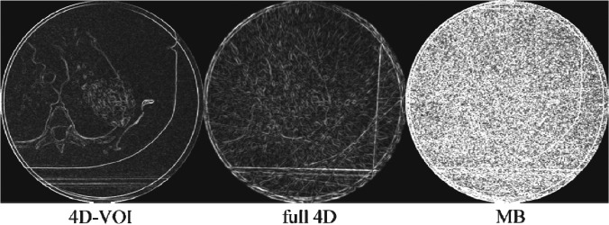
Patient 2, edge-detection filter processing on the 4D-VOI, full 4D, and MB reconstructions.
Light gray cross-hairs are included as a reference for respiratory motion. Patient 1 had a large 5-cm-diameter tumor in the right lung. It was known from 4D-CT imaging in treatment planning that this tumor had a known superior–inferior motion of 15 mm with a period of 2.8 s; the tumor motion was correctly measured by all three methods (4D-VOI, full 4D, and MB). Patient 2 had a 3-cm tumor near the apex of the left lung known to move only 3 mm in the anterior–posterior direction with a period of 3.2 s. Again, all three methods correctly measured the tumor motion.
The 4D-VOI images show no streak artifact except inside the VOI, whereas the full 4D images show artifact over the entire image. In the full 4D images for patient 1 (Figs. 1213), any structure boundaries are lost (the shape of the vertebral body and the ribs). The relatively uniform region in the heart shows large variations in the full 4D image. The edge-filtered images in Fig. 14 show streak artifacts along the heart and the chest wall boundaries. For patient 2, the full 4D reconstruction produced streak artifacts which distorted the vertebrae, scapula, and other bony anatomy (Figs. 1516). The edge-filtered image for the full 4D reconstruction (Fig. 17) shows strong streak artifacts tangent to the patient skin and the table.
The MB reconstructions reduced the streak artifacts but did not completely eliminate them. Regions outside the VOI show better quality than the full 4D reconstruction because of the streak artifact reduction. The MB reconstruction also added a hazy texture artifact. The coronal views (Figs. 1316) suffer more from this artifact than the axial views The tumor boundary and the shape of the ribs in the MB images are not as clear as in the other reconstructions. Further investigation is warranted to explain the poor image quality in the coronal views of the MB reconstruction.
Although a motion blur was seen in the phantom study, this degradation was not observed in these patient studies, possibly because the data acquisitions were different. For the phantom study, we used an asymmetric (i.e., offset) detector with a 360-deg gantry rotation, while the patient studies used a symmetric detector with 200-deg gantry rotation. An offset detector does not necessarily illuminate the target lesion in all views. Furthermore, some parts of the field of view may receive redundant (conjugate) views in a 360-deg rotation, would not happen with a 200-deg rotation. Again, further investigation of the MB algorithm may be needed to understand the relationship between the motion blur and the configuration of data acquisition.
The CNR was measured for the heart against the lung background. It was not surprising that the 4D-VOI reconstruction had the largest CNR (7.6), because it was composed mostly of the static (3D) image, which was reconstructed from a large number of projections. The CNR of the full-4D (2.5) reconstruction was low due to streak artifacts. The CNR was slightly lower for the MB reconstruction (2.4) than for the full 4D reconstruction. CNR in the MB reconstruction was degraded from the amplification of quantum noise in the algorithm.
DISCUSSION
We have presented a 4D-CBCT image reconstruction algorithm for undersampled raw data, which produces better image quality than other analytical reconstruction algorithms. The image quality improvement is achieved through the reduction of undersampling (streak) artifacts. We are able to reduce the artifacts by relaxing the requirement of reconstructing 4D image data to only a small volume-of-interest. In IGRT, 4D image data may not be needed necessarily for the entire image volume.
The 4D-VOI reconstruction was inspired by the previous research in interior tomography, which addresses the problem of exact CT reconstruction within a small region of interest, when the projection data are truncated.37, 38, 39, 40, 41 Whereas these reconstruction algorithms addressed the problem of VOI reconstruction when projection data are truncated, our present work addressed the problem of VOI reconstruction when angular sampling is incomplete.
Both the standard (full 4D) and 4D-VOI reconstructions were able to resolve the target motion for the 1-min data acquisitions. This suggests that the 1-min raw data contain sufficient information to determine the tumor motion, even though there are numerous global streak artifacts upon standard reconstruction. In addition to the position and motion of the lung tumor, the location of other structures elsewhere is also important for patient setup. For instance, the lung tumor could be perfectly localized, but a rotational error could introduce large errors in the dose distribution. Therefore, the image quality outside the target VOI is also important. The 4D-VOI reconstruction was able to almost completely eliminate the streak artifacts outside of the VOI in the simulation, chest phantom, and patient studies. The numerous streak artifacts outside the VOI in the full 4D reconstruction degrades structures such as the vertebrae, the rib cage, the heart, the chest wall as well as the other tissue interfaces. These degradations increase the uncertainty of positions of these structures and may introduce errors in the patient setup.
There are several other advantages in using our 4D-VOI reconstruction method. The 4D portion of the image is inherently and automatically registered to the 3D background anatomy. The 4D-VOI method does not require a symmetric (centered) detector configuration. The typical size of flat panel detectors (40 cm in the transverse direction) limits the coverage the field of view to approximately 25 cm. The 4D-VOI reconstruction can use an asymmetric (offset) detector for a larger field of view. This coverage can thus include the body outline for most patients larger than 25 cm in diameter. Furthermore, our method requires much less computation time than iterative reconstruction algorithms and can be implemented in a clinical setting. Last, our 4D-VOI method is based on the standard Feldkamp FBP algorithm, which has been extensively studied and optimized for many different situations (including tumor size, tumor shape, and patient size.) One limitation is that the 4D-VOI reconstruction does require a human intervention in the VOI selection. However, this limitation is mitigated by the fact that such a VOI is typically previously determined during the treatment planning. This information can be imported from the treatment plan and used to determine the VOI in the 4D-VOI reconstruction.
Compared with conventional 3D CBCT, we observed a reduced motion blur and improved target localization. We have also reduced the streak artifacts that may introduce errors in the patient setup. One potential application of 4D-CBCT is gated therapy, in which the treatment beam is turned on only during a specific portion of the respiratory cycle. This would allow the reduction of target volumes for patients with large amplitude of lung tumor motion.
CONCLUSIONS
4D-VOI reconstruction effectively reduces undersampling artifacts and resolves lung tumor motion in 4D-CBCT when using undersampled acquisition data. The 4D-VOI reconstruction is computationally inexpensive compared with more sophisticated iterative algorithms which may not be clinically practical. The improved image quality is achieved with a minor modification to the standard Feldkamp FBP algorithm. Compared with other 4D-CBCT image reconstructions that relate to streak artifact reduction and incomplete data sampling, our 4D-VOI reconstruction is an attractive alternative in 4D-CBCT for reconstructing target motion with 1-min acquisitions without generating numerous streak artifacts.
ACKNOWLEDGMENTS
This work was supported by research funding from Varian Medical Systems and fellowship funding from the Schissler family foundation.
References
- Cho P. S., Johnson R. H., and Griffin T. W., “Cone-beam CT for radiotherapy applications,” Phys. Med. Biol. 40, 1863–1883 (1995). 10.1088/0031-9155/40/11/007 [DOI] [PubMed] [Google Scholar]
- Jaffray D. A., Siewerdsen J. H., Wong J. W., and Martinez A. A., “Flat-panel cone-beam computed tomography for image-guided radiation therapy,” Int. J. Radiat. Oncol. Biol. Phys. 53, 1337–1349 (2002). 10.1016/S0360-3016(02)02884-5 [DOI] [PubMed] [Google Scholar]
- Letourneau D. et al. , “Online planning and delivery technique for radiotherapy of spinal metastases using cone-beam CT: Image quality and system performance,” Int. J. Radiat. Oncol. Biol. Phys. 67, 1229–1237 (2007). 10.1016/j.ijrobp.2006.09.058 [DOI] [PubMed] [Google Scholar]
- Purdie T. G. et al. , “Cone-beam computed tomography for on-line image guidance of lung stereotactic radiotherapy: Localization, verification, and intrafraction tumor position,” Int. J. Radiat. Oncol. Biol. Phys. 68, 243–252 (2007). 10.1016/j.ijrobp.2006.12.022 [DOI] [PubMed] [Google Scholar]
- Wang Z., Wu Q. J., Marks L. B., Larrier N., and Yin F. F., “Cone-beam CT localization of internal target volumes for stereotactic body radiotherapy of lung lesions,” Int. J. Radiat. Oncol. Biol. Phys. 69, 1618–1624 (2007). 10.1016/j.ijrobp.2007.08.030 [DOI] [PubMed] [Google Scholar]
- Grills I. S. et al. , “Image-guided radiotherapy via daily online cone-beam CT substantially reduces margin requirements for stereotactic lung radiotherapy,” Int. J. Radiat. Oncol. Biol. Phys. 70, 1045–1056 (2008). 10.1016/j.ijrobp.2007.07.2352 [DOI] [PubMed] [Google Scholar]
- Li H. et al. , “Comparison of 2D radiographic images and 3D cone beam computed tomography for positioning head-and-neck radiotherapy patients,” Int. J. Radiat. Oncol. Biol. Phys. 71, 916–925 (2008). 10.1016/j.ijrobp.2008.01.008 [DOI] [PubMed] [Google Scholar]
- Nijkamp J. et al. , “Adaptive radiotherapy for prostate cancer using kilovoltage cone-beam computed tomography: First clinical results,” Int. J. Radiat. Oncol. Biol. Phys. 70, 75–82 (2008). 10.1016/j.ijrobp.2007.05.046 [DOI] [PubMed] [Google Scholar]
- International Commission on Radiation Units and Measurements, “Prescribing, recording, and Reporting Photon Beam Therapy,” Report No. 50, 1993. [Google Scholar]
- Sonke J. J., Zijp L., Remeijer P., and van Herk M., “Respiratory correlated cone beam CT,” Med. Phys. 32, 1176–1186 (2005). 10.1118/1.1869074 [DOI] [PubMed] [Google Scholar]
- Kriminski S. et al. , “Respiratory correlated cone-beam computed tomography on an isocentric C-arm,” Phys. Med. Biol. 50, 5263–5280 (2005). 10.1088/0031-9155/50/22/004 [DOI] [PubMed] [Google Scholar]
- Dietrich L., Jetter S., Tucking T., Nill S., and Oelfke U., “Linac-integrated 4D cone beam CT: First experimental results,” Phys. Med. Biol., 51, 2939–2952 (2006). 10.1088/0031-9155/51/11/017 [DOI] [PubMed] [Google Scholar]
- Li T. et al. , “Four-dimensional cone-beam computed tomography using an on-board imager,” Med. Phys. 33, 3825–3833 (2006). 10.1118/1.2349692 [DOI] [PubMed] [Google Scholar]
- Lu J. et al. , “Four-dimensional cone beam CT with adaptive gantry rotation and adaptive data sampling,” Med. Phys. 34, 3520–3529 (2007). 10.1118/1.2767145 [DOI] [PubMed] [Google Scholar]
- Feldkamp L. A., Davis L. C., and Kress J. W., “Practical cone-beam algorithm,” J. Opt. Soc. Am. A 1, 612–619 (1984). 10.1364/JOSAA.1.000612 [DOI] [Google Scholar]
- Purdie T. G. et al. , “Respiration correlated cone-beam computed tomography and 4DCT for evaluating target motion in Stereotactic Lung Radiation Therapy,” Acta. Oncol. 45, 915–922 (2006). 10.1080/02841860600907345 [DOI] [PubMed] [Google Scholar]
- Harsolia A., Hugo G. D., Kestin L. L., Grills I. S., and Yan D., “Dosimetric advantages of four-dimensional adaptive image-guided radiotherapy for lung tumors using online cone-beam computed tomography,” Int. J. Radiat. Oncol. Biol. Phys. 70, 582–589 (2008). 10.1016/j.ijrobp.2007.08.078 [DOI] [PubMed] [Google Scholar]
- Sonke J. J., Rossi M., Wolthaus J., van Herk M., Damen E., and Belderbos J., “Frameless stereotactic body radiotherapy for lung cancer using four-dimensional cone beam CT guidance,” Int. J. Radiat. Oncol. Biol. Phys. 74(2), 567–574 (2008). 10.1016/j.ijrobp.2008.08.004 [DOI] [PubMed] [Google Scholar]
- Li T. and Xing L., “Optimizing 4D cone-beam CT acquisition protocol for external beam radiotherapy,” Int. J. Radiat. Oncol. Biol. Phys. 67, 1211–1219 (2007). 10.1016/j.ijrobp.2006.10.024 [DOI] [PubMed] [Google Scholar]
- Bergner F., Berkus T., Oelhafen M., Kunz P., Pan T., and Kachelriess M., “Autoadaptive phase-correlated (AAPC) reconstruction for 4D CBCT,” Med. Phys. 36, 5695–5706 (2009). 10.1118/1.3260919 [DOI] [PMC free article] [PubMed] [Google Scholar]
- Mc Kinnon G. C. and Bates R. H. T., “Towards imaging the beating heart usefully with a conventional CT scanner,” IEEE Trans. Biomed. Eng. BME- 28, 123–127 (1981). 10.1109/TBME.1981.324785 [DOI] [PubMed] [Google Scholar]
- Leng S. et al. , “Streaking artifacts reduction in four-dimensional cone-beam computed tomography,” Med. Phys. 35, 4649–4659 (2008). 10.1118/1.2977736 [DOI] [PMC free article] [PubMed] [Google Scholar]
- Bergner F. et al. , “An investigation of 4D cone-beam CT algorithms for slowly rotating scanners,” Med. Phys. 37, 5044–5053 (2010). 10.1118/1.3480986 [DOI] [PubMed] [Google Scholar]
- Sidky E. Y., Kao C. M., and Pan X., “Accurate image reconstruction from few-views and limited-angle data in divergent-beam CT,” J. X-Ray. Sci. Technol. 14, 119–139 (2006). [Google Scholar]
- Sidky E. Y. and Pan X., “Image reconstruction in circular cone-beam computed tomography by constrained, total-variation minimization,” Phys. Med. Biol. 53, 4777–4807 (2008). 10.1088/0031-9155/53/17/021 [DOI] [PMC free article] [PubMed] [Google Scholar]
- Chen G. H., Tang J., and Leng S., “Prior image constrained compressed sensing (PICCS),” Proc. Soc. Photo. Opt. Instrum. Eng. 6856, (2008). 10.1117/12.770532 [DOI] [PMC free article] [PubMed]
- Leng S., Tang J., Zambelli J., Nett B., Tolakanahalli R., and Chen G. H., “High temporal resolution and streak-free four-dimensional cone-beam computed tomography,” Phys. Med. Biol. 53, 5653–5673 (2008). 10.1088/0031-9155/53/20/006 [DOI] [PMC free article] [PubMed] [Google Scholar]
- Bian J. et al. , “Evaluation of sparse-view reconstruction from flat-panel-detector cone-beam CT,” Phys. Med. Biol. 55, 6575–6599 (2010). 10.1088/0031-9155/55/22/001 [DOI] [PMC free article] [PubMed] [Google Scholar]
- Pan X., Sidky E. Y., and Vannier M., “Why do commercial CT scanners still employ traditional, filtered back-projection for image reconstruction?,” Inverse Probl. 25, 1230009 (2009). 10.1088/0266-5611/25/12/123009 [DOI] [PMC free article] [PubMed] [Google Scholar]
- Wang Z., Han G., Li T., and Liang Z., “Speedup OS-EM image reconstruction by PC graphics card technologies for quantitative SPECT with varying focal-length fan-beam collimation,” IEEE Trans. Nucl. Sci. 52, 1274–1280 (2005). 10.1109/TNS.2005.858231 [DOI] [PMC free article] [PubMed] [Google Scholar]
- Xu F. and Mueller K., “Accelerating popular tomographic reconstruction algorithms on commodity PC graphics hardware,” IEEE Trans. Nucl. Sci. 52, 654–663 (2005). 10.1109/TNS.2005.852703 [DOI] [Google Scholar]
- Xu F. and Mueller K., “Real-time 3D computed tomographic reconstruction using commodity graphics hardware,” Phys. Med. Biol. 52, 3405–3419 (2007). 10.1088/0031-9155/52/12/006 [DOI] [PubMed] [Google Scholar]
- Noel P. B., Walczak A. M., Xu J., Corso J. J., Hoffmann K. R., and Schafer S., “GPU-based cone beam computed tomography,” Comput. Methods. Programs. Biomed. 98(3), 271–277 (2009). 10.1016/j.cmpb.2009.08.006 [DOI] [PubMed] [Google Scholar]
- Kak A. C. and Slaney M., “Summary of Shepp-Logan phantom parameters for tomographic imaging,” in Principles of Computerized Tomographic Imaging (Society for Industrial and Applied Mathematics, New York, 2001). pp. 53–55. [Google Scholar]
- Keall P. J., Kini V. R., Vedam S. S., and Mohan R., “Potential radiotherapy improvements with respiratory gating,” Australas. Phys. Eng. Sci. Med. 25, 1–6 (2002). 10.1007/BF03178368 [DOI] [PubMed] [Google Scholar]
- http://rsb.info.nih.gov/ij/. Last accessed June 2011.
- Zou Y. and Pan X., “An extended data function and its generalized backprojection for image reconstruction in helical cone-beam CT,” Phys. Med. Biol. 49, N383–N387 (2004). 10.1088/0031-9155/49/22/N02 [DOI] [PubMed] [Google Scholar]
- Cho S., Bian J., Pelizzari C. A., Chen C. T., He T. C., and Pan X., “Region-of-interest image reconstruction in circular cone-beam microCT,” Med. Phys. 34, 4923–4933 (2007). 10.1118/1.2804924 [DOI] [PubMed] [Google Scholar]
- Ye Y., Yu H., and Wang G., “Exact Interior Reconstruction with Cone-Beam CT,” Int. J. Biomed. Imaging 2007, 10693 (2007). [DOI] [PMC free article] [PubMed] [Google Scholar]
- Ye Y., Yu H., Wei Y., and Wang G., “A general local reconstruction approach based on a truncated hilbert transform,” Int. J. Biomed. Imaging 2007, 63634 (2007). [DOI] [PMC free article] [PubMed] [Google Scholar]
- Yu H. and Wang G., “Feldkamp-type VOI reconstruction from super-short-scan cone-beam data,” Med. Phys. 31, 1357–1362 (2004). 10.1118/1.1739298 [DOI] [PubMed] [Google Scholar]


