Abstract
Purpose: Intrafraction deformation limits targeting accuracy in radiotherapy. Studies show tumor deformation of over 10 mm for both single tumor deformation and system deformation (due to differential motion between primary tumors and involved lymph nodes). Such deformation cannot be adapted to with current radiotherapy methods. The objective of this study was to develop and experimentally investigate the ability of a dynamic multi-leaf collimator (DMLC) tracking system to account for tumor deformation.
Methods: To compensate for tumor deformation, the DMLC tracking strategy is to warp the planned beam aperture directly to conform to the new tumor shape based on real time tumor deformation input. Two deformable phantoms that correspond to a single tumor and a tumor system were developed. The planar deformations derived from the phantom images in beam's eye view were used to guide the aperture warping. An in-house deformable image registration software was developed to automatically trigger the registration once new target image was acquired and send the computed deformation to the DMLC tracking software. Because the registration speed is not fast enough to implement the experiment in real-time manner, the phantom deformation only proceeded to the next position until registration of the current deformation position was completed. The deformation tracking accuracy was evaluated by a geometric target coverage metric defined as the sum of the area incorrectly outside and inside the ideal aperture. The individual contributions from the deformable registration algorithm and the finite leaf width to the tracking uncertainty were analyzed. Clinical proof-of-principle experiment of deformation tracking using previously acquired MR images of a lung cancer patient was implemented to represent the MRI-Linac environment. Intensity-modulated radiation therapy (IMRT) treatment delivered with enabled deformation tracking was simulated and demonstrated.
Results: The first experimental investigation of adapting to tumor deformation has been performed using simple deformable phantoms. For the single tumor deformation, the Au+Ao was reduced over 56% when deformation was larger than 2 mm. Overall, the total improvement was 82%. For the tumor system deformation, the Au+Ao reductions were all above 75% and the total Au+Ao improvement was 86%. Similar coverage improvement was also found in simulating deformation tracking during IMRT delivery. The deformable image registration algorithm was identified as the dominant contributor to the tracking error rather than the finite leaf width. The discrepancy between the warped beam shape and the ideal beam shape due to the deformable registration was observed to be partially compensated during leaf fitting due to the finite leaf width. The clinical proof-of-principle experiment demonstrated the feasibility of intrafraction deformable tracking for clinical scenarios.
Conclusions: For the first time, we developed and demonstrated an experimental system that is capable of adapting the MLC aperture to account for tumor deformation. This work provides a potentially widely available management method to effectively account for intrafractional tumor deformation. This proof-of-principle study is the first experimental step toward the development of an image-guided radiotherapy system to treat deforming tumors in real-time.
Keywords: DMLC tracking, tumor deformation, adaptation
INTRODUCTION
Intrafraction tumor motion can impair the efficacy of radiotherapy, especially for highly conformal and hypofractionated treatments, e.g., stereotactic body radiation therapy. Various intrafraction motion management strategies that are under investigation include: moving the treatment device head,1, 2 moving the patient by shifting the treatment couch,3 gating the radiation delivery with the respiratory cycle,4 and changing the beam apertures using the dynamic multi-leaf collimator (DMLC).5, 6, 7, 8, 9, 10, 11, 12, 13, 14, 15 The first three techniques move or hold the treatment beam in a rigid manner and thus can only account for rigid tumor displacement or rotation. Compensation for more complex tumor deformation requires reshaping the beam apertures using the DMLC.
Several studies in the literature have reported the quantitative deformation magnitude of a single tumor. With four-dimensional computed tomography (4DCT) images, Kyriakou and McKenzie16 observed significant superior-inferior (SI) strain of lung tumors in three patients and the maximum tumor SI extent change was more than 10 mm. Liu et al.17 measured the lung tumor deformation as the difference between the tumor motion computed using deformable registration and rigid-body registration. The largest deformation was 2.7 mm in SI direction between the inspiration and expiration phases on CT images. By examining the cine-MRI images of 17 pancreatic cancer patients, Feng et al.18 reported up to 5 mm deformation in the SI direction. Using the Calypso system and cine-MRI, Burch et al.19 and Ghilezan et al.20 analyzed the motion of several sample points inside the target volume and reported that the prostate deformation was around 1 mm. Instead of directly assessing the tumor deformation itself, Lu et al.21 found that an extra 3 mm planning margin was required to ensure a 95% PTV coverage due to tumor deformation for 12 lung cancer patients and an even larger margin for 5 upper abdominal patients.
In addition to single tumor deformation, the relative motion between multiple target volumes can be viewed as the deformation of the composite tumor system, which is common in advanced stage disease. Donnelly et al.22 and Pantarotto et al.23 observed larger than 10 mm independent movement both for the primary lung tumor and the involved mediastinal and hilar lymph nodes. In prostate cancer, the metastatic pelvic lymph nodes are presumed to be fixed with respect to the bone whereas the prostate can move more than 15 mm.24, 25 Also, the seminal vesicles (SVs) are often included in the treatment and the independent motion between the prostate and SVs constitutes a deforming tumor target.26 Such tumor system deformation is difficult to compensate if only one target is tracked with current motion management, but is naturally within the scope of the developed deformation tracking strategy. These reported observations are summarized in Table 1.
Table 1.
Patient tumor deformation measurements.
| Deformation type | Tumor site | Magnitude | Imaging method | No. of patients | Reference |
|---|---|---|---|---|---|
| Single tumor deformation | Lung | max >10 mm | 4DCT | 6 | Kyriakou and McKenzie (Ref. 16) |
| max 2.7 mm | 4DCT | 10 | Liu et al. (Ref. 17) | ||
| Pancreas | up to 5 mm | Cine-MRI | 17 | Feng et al. (Ref. 18) | |
| Prostate | <1 mm | Calypso | 11 | Burch et al. (Ref. 19) | |
| Cine-MRI | 6 | Ghilezan et al. (Ref. 20) | |||
| Tumor system deformation | Lung – lymph node | Nodes max >10 mm and uncorrelated primary-nodes motion | 4DCT | 20 | Donnelly et al. (Ref. 22) |
| 4DCT | 41 | Pantarotto et al. (Ref. 23) | |||
| Prostate – lymph node | max >10 mm for 1.3% of time | Calypso | 17 | Langen et al. (Ref. 24) | |
| max >15 mm | kV images | 10 | Ng et al. (Ref. 25) |
Real-time DMLC tracking of intrafraction tumor motion has been under continuous investigation over the past decade on different linear accelerator (linac) models integrated with various motion detection techniques.5, 6, 7, 8, 9, 10, 11, 12, 13, 14, 15 The first clinical trial of intrafractional prostate tumor motion adaptation by real-time DMLC tracking on a Varian Trilogy linear accelerator (Varian Medical System, Palo Alto, CA) started in November 2013.27 However, so far these systems are only able to account for rigid tumor displacement or rotation. In this study, for the first time, we extended the DMLC tracking system to account for intrafractional tumor deformation and tested experimentally. Theoretical leaf sequencing algorithms to preserve the planned intensity for deforming tumors incorporating real time tumor deformation update were reported by Papiez et al.28 and Tacke et al.,29 but with the simplification of one dimensional deformation. Our approach is to warp the planned beam aperture directly to conform to the new tumor shape based on real time tumor deformation input. The DMLC tracking software was further developed to process the acquired tumor deformation, calculate the new leaf sequences, and perform postprocessing analysis. Preliminary evaluation of the tracking performance was performed by simple deformable phantom experiments in a clinical setting.
Due to the unavailability of in-room 3D volumetric imaging, the deformations were designed to be symmetric around the SI axis and 2D kV images were acquired to compute the 2D deformation vector field (DVF) using an in-house deformable image registration (DIR) software. Because the DIR process took several seconds, in the experiment, the phantoms only proceeded to the next deformation position until DVF computation of current deformation position completed. The experimental setup and implementations are explained in more detail in Sec. 2A.
It should be noted that the focus of the current study is to demonstrate that if guided by proper deformation information, the DMLC tracking system can improve the target coverage for deforming targets. The development of deformable registration algorithms with higher accuracy or faster speed for multiple imaging modalities and anatomy sites is critical to translate the technique into clinical practice but beyond the scope of this paper.
METHOD
Deformable phantom experiment
The phantom experiments were performed on a Varian Trilogy linear accelerator equipped with a kV On-Board Imager (OBI) system and Millennium 120-leaf MLC. As mentioned earlier, because there is no in-room volumetric imaging device available currently in the clinic, only the 2D deformation in beam's eye view (BEV) was considered in the experiments. Because the target could move out of the field after deformation, and especially in Intensity Modulated Radiation Therapy (IMRT), the target was only partially seen in BEV; as a consequence the 2D MV portal images could not be used to derive the deformation of the whole target. Therefore, we designed the phantom deformation to be symmetric around the SI axis, so that the deformation viewed from BEV was the same as that imaged by the lateral OBI. In this way, we acquired the target deformation in BEV based on the 2D target images taken by the orthogonally mounted OBI.
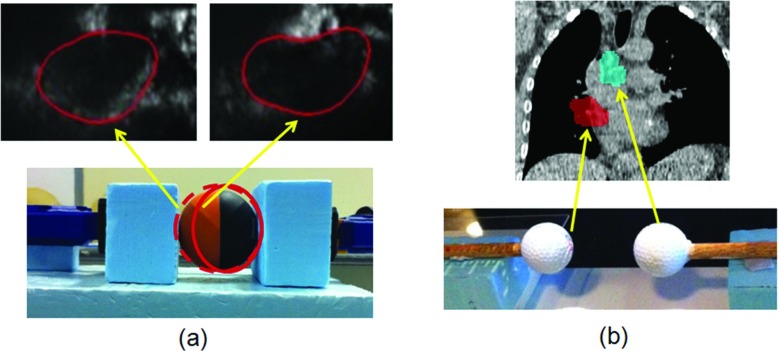
The deformable phantoms simulating the single tumor deformation and the tumor system deformation are shown in Fig. 1. A rubber ball (59 mm diameter) phantom was used for the single tumor deformation tracking experiment. The ball was held by a clamp and the deformation was generated by compressing the ball with the clamp from one end. The phantom was deformed with seven compressions up to 10.4 mm. A pair of golf balls (43 mm diameter) was used for the tumor system deformation tracking experiment. The superior ball was kept static and the inferior ball was translated inferiorly to generate the deformation, i.e., the relative motion between the two balls. The moving ball was shifted 8 times up to 21.5 mm.
Figure 1.
Adaptive deformation radiotherapy experiments were performed for two scenarios: (a) Single tumor deformation representing morphologic changes of the primary tumor and (b) tumor system deformation, representing independent motion of a primary tumor and involved node.
Conformal plans containing a single MLC field were prepared for the phantoms at the reference position without deformation. For the single deformation phantom, the reference plan was a 70 mm diameter circular aperture encompassing the phantom plus a 5.5 mm margin. Since the deformation was mainly at the SI direction, the collimator angle was rotated to 90° so that the leaf travel direction was parallel to the deformation direction. For the system deformation phantom, the reference plan was two 50 mm diameter apertures 20 mm apart encompassing the phantom balls plus a 3.5 mm margin. The leaf travel direction had to be perpendicular to the deformation direction in order to form the two isolated apertures. The MLC apertures were kept at the central MLC field where the leaf width was finer of 5 mm.
The target deformation was computed by an in-house software which used the B-spline DIR algorithm in the Insight Segmentation and Registration Toolkit (ITK) library.30 The deformation was modeled by a cubic B-spline defined on a lattice of points overlaid evenly on the image. Multiresolution framework was used with two levels of B-spline pyramids. The performance of the B-spline DIR algorithm was examined by matching the warped target contour to the target contour on the fixed source image. The Dice coefficients were above 99% for all cases and the Hausdorff distance, which measured the boundary mismatch, was within 1 mm for the single tumor phantom (deformation magnitude up to 10.4 mm) and within 2.5 mm for the tumor system phantom (deformation magnitude up to 21.5 mm). The pixel size was 0.26 mm.
In the experiments, the DIR software was run at the OBI console computer equipped with a 2.27 GHz Intel Xeon E5520 processor and 4 GB RAM. The time taken to register a pair of 370 × 340 pixel images ranged from 8 to 17 s, which was not sufficiently fast for a real-time implementation. Therefore, we implemented the experiment in the way that the phantoms only proceeded to the next deformation position until DVF computation of the current deformation position was completed. Although this limitation inhibited latency analysis for the real-time system, the experiment represented a proof of principle of the clinical application. The computation time limitations can be improved, as expanded upon in Sec. 4, enabling real-time deformation tracking in future work.
DMLC tracking system
Tracking tumor deformation using DMLC fits in the framework of the original DMLC tracking system, which was developed to compensate for intrafractional tumor translation by shifting the preplanned beam aperture to follow the moving tumor.5 The required displacement vector is obtained in real-time by tracking the implanted marker using x-ray imaging7, 8, 9, 10 or electromagnetic signals.6 To compensate for intrafractional tumor deformation, the tracking software was developed to warp the preplanned beam aperture to conform to the new tumor shape. As explained earlier, to obtain the required deformation map (i.e., DVF) for aperture warping in our experiments, the phantom's 2D x-ray images symmetric to BEV were used in deformable image registration. The displacement vectors along the MLC aperture boundary were obtained by bilinear interpolation of the calculated 2D DVF matrix. The DIR software is standalone and can automatically start the registration once a new image is acquired. The calculated DVF is transferred to the tracking software through TCP/IP communication. The aperture warping starts on the tracking software once all the data packets of a DVF have been received.
The new beam shape obtained from warping the preplanned aperture boundary needs to be fitted by the MLC leaves to be deliverable. The leaf positions are recalculated to best approximate the new beam shape using a previously developed leaf fitting algorithm.31 The algorithm is based on an optimized tradeoff between the target underdose and healthy tissue overdose cost and takes into account the physical constraints of the MLC, such as finite leaf width, leaf travel velocity, and restricted shape topology due to the paired leaf structure.
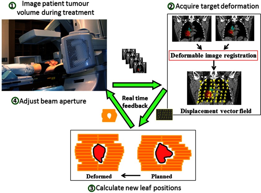
After the new leaf positions have been determined, the information is sent to the MLC controller and the beam shape is adjusted on the linear accelerator. The tracking workflow of the envisaged clinical implementation is illustrated in Fig. 2, in which the data stream forms a real-time feedback loop.
Figure 2.
The envisaged clinical workflow diagram with real time feedback loop for the intrafraction tumor deformation tracking system. The patient is simultaneously imaged during treatment to acquire the tumor deformation. The obtained displacement vector field (DVF) is then used to adapt the planned MLC aperture. The MLC leaves then move to the new position to compensate for the tumor deformation.
Geometric target coverage analysis
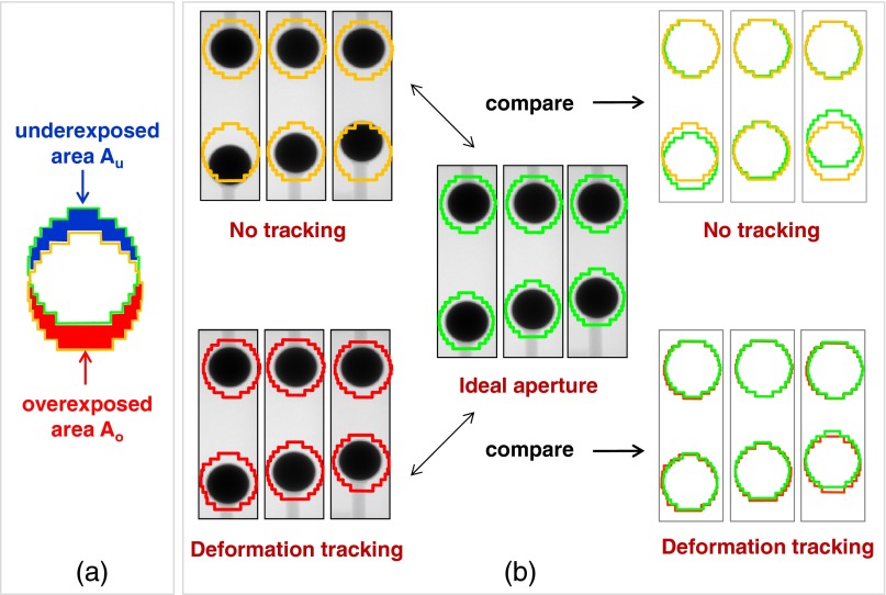
The tracking accuracy in the phantom deformation tracking experiments was evaluated by a geometric target coverage quantity, which was defined as the sum of the area incorrectly outside (the underexposed area Au) and inside (the overexposed area Ao) the ideal MLC aperture,32, 33 as illustrated in Fig. 3a. As the benchmark, the ideal MLC apertures for the deformed phantom was defined as the aperture conformal to the deformed target and were created by autocontouring the deformed target on the acquired kV image, expanding the contour by the same margin, and applying the same leaf fitting algorithm as described in Secs 2A, 2B.
Figure 3.
(a) Illustration of the metrics of underexposed and overexposed areas that are used to evaluate the geometric target coverage. (b) Illustration of comparing the geometric target coverage of deformation tracking to no-tracking deliveries at three deformation positions.
As shown in Fig. 3b, the sum of the underexposed area Au and overexposed area Ao (hereafter denoted as Au+Ao) of the actually delivered aperture after applying deformation tracking was compared to the Au+Ao if no deformation tracking applied (i.e., the delivered apertures remained as the planned shape when target deformed) for all deformation positions.
Ravkilde et al.33 showed that Au+Ao correlated well with the 3%/3 mm γ-test failure rate (mean of Pearson r = 0.83, p < 0.001) at any point in time during tumor translation tracking. Therefore, the overexposed and underexposed area quantified here can be assumed to be a reasonable indicator of the dosimetric error of the delivery.
Two consecutive steps during deformation tracking contributed to tracking uncertainty: deformation acquisition through image registration and leaf fitting due to finite MLC leaf width. The contribution from the image registration alone, denoted as (Au+Ao)DIR, was defined as the Au+Ao between thebeam shape of the ideal aperture before leaf fitting (i.e., the segmented deformed target contour expanded by the corresponding margin) and the beam shape warped from the reference shape (i.e., the segmented undeformed target contour expanded by the corresponding margin) using the calculated DVF before leaf fitting.
Clinical proof-of-principle experiment
To represent a realistic clinical tracking scenario, we performed a clinical proof of principle tracking experiment on the linac with previously acquired 2D cine MR images of a female nonsmall cell lung cancer patient. A conformal MLC field was manually created on the reference inspiration image and taken as the planned aperture. The cine MR images were read by the image registration software; the DVFs were calculated and transferred to the DMLC tracking software which refitted the MLC field shapes and updated on the linac. Despite the tracking latency, this process represented a potential clinical MRI-linac deformation tracking treatment.
IMRT simulations
In order to be able to know the ideal MLC aperture for the deformed targets to assess the geometric target coverage, the treatment plans of the phantom experiments were both simple conformal fields. It is of more clinical interest to apply the developed deformation tracking strategy for IMRT treatment. We created dynamic (sliding window) IMRT plans for the single tumor deformation and tumor system deformation phantoms. Instead of delivering the IMRT plans on the linear accelerator used for the conformal and clinical proof-of-principle demonstration, a linac simulation software was used to communicate directly with the DMLC tracking software in the same manner as if an actual linac was present. The linac machine status such as gantry angle, MLC leaf positions, dynamic dose fraction, etc. was returned to the tracking software by the linac simulation software. The same deformation images acquired in the phantom experiments (Sec. 2A.) were read by the deformable image registration software for the DVF calculation and used to deform the IMRT field apertures. Because the IMRT fields only covered a fraction of the target at any given time, without knowing the ground truth of the target deformation, there is no true knowledge of the “ideal” MLC aperture for each warped IMRT segment. Instead, we used the morphed MLC aperture before leaf fitting as a good approximation of the ideal aperture in the geometric target coverage analysis. A dosimetric study is required to give more accurate quantitative evaluation of the deformation tracking performance for IMRT, which is however beyond the scope of this paper since a 3D deformable dosimeter is still under investigation, as expanded upon in Sec. 4.
RESULTS
Phantom experiments
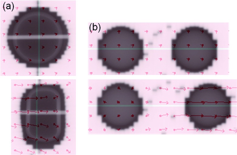
Example portal images during deformable tracking for the single tumor deformation and tumor system deformation are shown in Fig. 4. The vector fields are overlaid on the images indicating the displacements from the reference image at the sampling points. See the supplementary material (Portal-Experiment-Single-Def-Tracking.mpg and Portal-Experiment-System-Def-Tracking.mpg)34 for the animated portal images of all the deformation positions of the two deformation tracking experiments.
Figure 4.
Example portal images showing the planned beam apertures with the phantoms of initial shape (upper rows) and the adapted beam apertures with the deformed phantoms (lower rows) based on the calculated DVF (overlaid red arrows) for (a) single tumor deformation and (b) tumor system deformation scenarios. Animated portal images of all deformation positions can be found in the supplementary material (Portal-Experiment-Single-Def-Tracking.mpg and Portal-Experiment-System-Def-Tracking.mpg) (Ref. 34).
The geometric target coverage metric Au+Ao of the deformation tracking and no-tracking delivery are plotted as a function of the deformation magnitude in Fig. 5. As the deformation magnitude increased, the under- and overexposed areas increased without tracking, but were well managed by deformation tracking. For the single tumor deformation, the Au+Ao was reduced over 56% when deformation was larger than 2 mm. Overall, the total improvement was 82%. For the tumor system deformation, the minimum deformation was 4 mm and the Au+Ao reductions were all above 75%. The total Au+Ao improvement was 86%.
Figure 5.
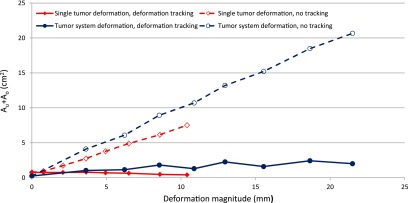
The sum of underexposed area and overexposed area Au + Ao with deformation tracking (solid lines) are compared to the no tracking deliveries (dashed lines) for single tumor phantom (diamond) and tumor system phantom (circle) as a function of the deformation magnitude.
To analyze the contributions to the tracking uncertainty, (Au+Ao)DIR solely due to image registration was calculated and compared to the total Au+Ao which reflected the combined effects of image registration and leaf fitting in Fig. 6. As expected, the dominant source of uncertainty was deformable image registration. It is interesting to notice that for single tumor deformation, leaf fitting actually mitigated the uncertainty, because the Au+Ao area was partially cancelled out when the smooth boundary was approximated by the 5 mm wide leaves. For tumor system deformation, because the deformation was perpendicular to the leaf travel direction, even 1–2 mm deformation magnitude error could lead to large differences in the fitted apertures. It appeared that when the deformation magnitude was around integer number of leaf width, i.e., when the phantom shape could be approximated by the MLC leaves with smaller discrepancy, the (Au+Ao)DIR was partially canceled out during leaf fitting. Otherwise Au+Ao increased during leaf fitting.
Figure 6.
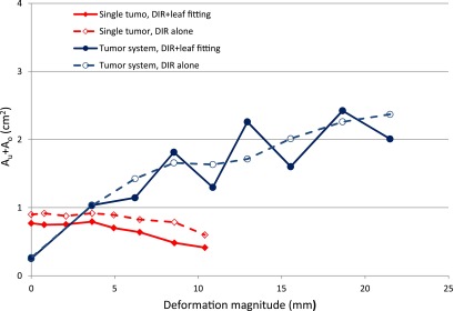
The sum of underexposed area and overexposed area Au + Ao in deformation tracking (solid lines) are compared to the contribution from the deformable image registration (DIR) alone, (Au + Ao)DIR, (dashed lines) for single tumor phantom (diamond) and tumor system phantom (circle) as a function of the deformation magnitude.
Clinical proof-of-principle experiment
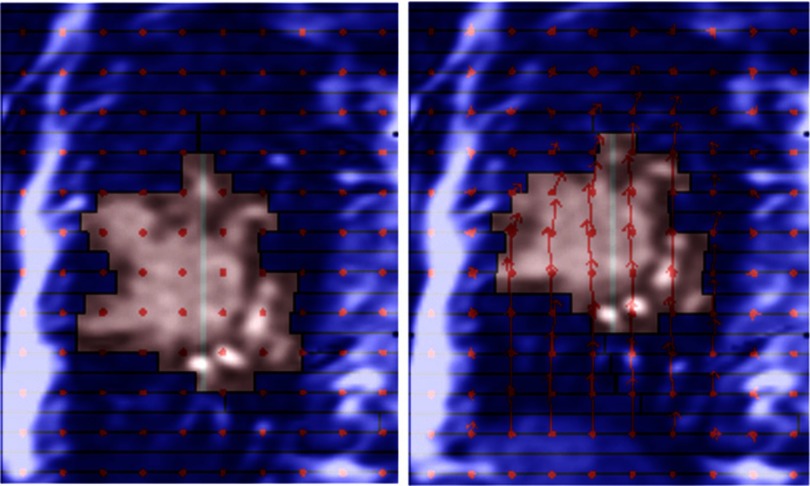
Using the previously acquired patient MR images, the proof-of-principle experiment visually demonstrated intrafraction deformation adaptation using DMLC tracking in MR-linac treatment environment. Figure 7 shows two example frames. The left image was at the reference inspiration phase. The tumor moved up and deformed on the right image, where the aperture was reshaped to conform to the tumor. See the supplementary material (Lung-Patient-MRI-Simulation-Def-tracking.mpg)34 for the animated tracking process over all deformation phases. But unlike the phantom experiments, there was no ground truth available for the “ideal” MLC field of the deformed anatomy, therefore no quantitative estimation of the tracking uncertainty could be extrapolated.
Figure 7.
Cinical proof-of-principle experiment using actual lung cancer patient images. The planned aperture (left) was adapted to conform to the deformed tumor (right). The background images were previously acquired 2D MRI images. Animated tracking process can be found in the supplementary material (Lung-Patient-MRI-Simulation-Def-tracking.mpg) (Ref. 34).
IMRT simulation
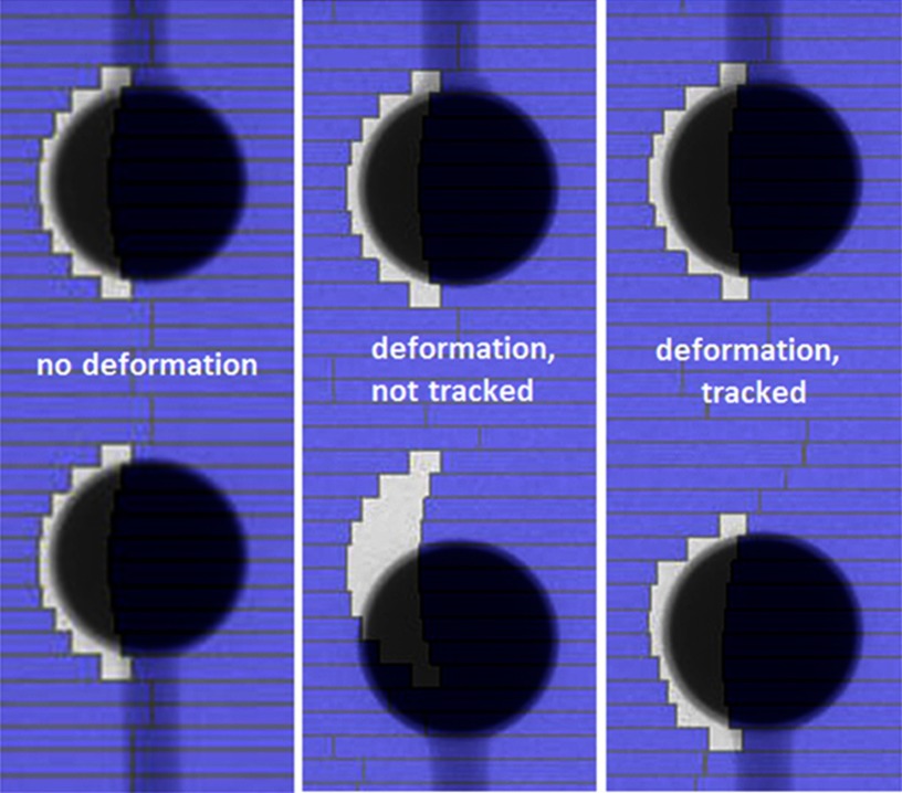
Deformation tracking using DMLC during delivery of a dynamic IMRT plan was simulated. Figures 89 show the example frame at a certain dose fraction for the scenario of (1) no deformation, (2) with deformation but without deformation tracking and (3) with deformation and deformation tracking for the single deformation and system deformation. See the supplementary material (IMRT-Simulation-Single-Def-Tracking.mpg and IMRT-Simulation-System-Def-Tracking.mpg)34 for the animated IMRT deliveries with and without deformation tracking.
Figure 8.

Example frame at one dose fraction of the simulated dynamic IMRT delivery to the single deformation phantom without deformation (left), with deformation and without deformation tracking (middle) and with deformation and deformation tracking (right). Animated IMRT deliveries to the deforming phantom with and without deformation tracking can be found in the supplementary material (IMRT-Simulation-Single-Def-Tracking.mpg) (Ref. 34).
Figure 9.
Example frame at one dose fraction of the simulated dynamic IMRT delivery to the system deformation phantom without deformation (left), with deformation and without deformation tracking (middle) and with deformation and deformation tracking (right). Animated IMRT deliveries to the deforming phantom with and without deformation tracking can be found in the supplementary material (IMRT-Simulation-System-Def-Tracking.mpg) (Ref. 34).
Although the ideal IMRT field for each deformation position was not known, we used the morphed MLC aperture before leaf fitting as the reference in the geometric target coverage analysis. As we have shown earlier, compared to the Au+Ao error without tracking, the contribution from registration in deformation tracking was small and the 1–2 mm deformable registration accuracy made the morphed aperture a good approximation of the ideal aperture. Similar to the conformal treatment, the geometric target coverage was improved by 88% for single target deformation and 79% for tumor system deformation.
DISCUSSION
This study is the first to demonstrate DMLC tracking to account for intrafraction tumor deformation. Other investigated motion management strategies, including beam gating, beam shifting, and couch tracking are limited to correcting beam-tumor alignment for rigid tumor motion only. As a proof of principle, we performed simple deformable phantom experiments to simulate DMLC tracking for two types of deformations. The evaluation of the geometric improvement gained by deformation tracking yielded promising experimental results for conformal radiotherapy.
Tumor deformation is three dimensional and should be derived from continuous volumetric images. The approach we took in this experiment was to obtain the 2D DVF at BEV plane from the 2D images symmetric to BEV projections. This was a reasonable approximation, while real-time in-room 3D imaging is not available. There are technologies that exist or are under development to meet this requirement. Li et al.35 developed a method to reconstruct 3D image and 3D tumor localization in real-time based on a single x-ray projection image given a set of training volumetric images obtained from either 4DCT or 4DCBCT. The recently available MRI (Refs. 36, 37, 38) and ultrasound39, 40 guided IGRT systems provide an ideal platform for real-time tumor deformation adaptation. Especially, the real-time MRI imaging has superior soft-tissue contrast and tumor boundary visualization. It delivers no extra radiation dose to the patient and does not require the placement of fiducial markers inside the patient. Once the 3D DVF becomes available in real time, it can then be collapsed to the 2D BEV plane by averaging the vectors in all voxels along the ray line of each beam angle as proposed by Feng et al.41 A foreseeable limitation of this method is that when the deformation vectors along the beam direction are in opposite directions, the warped aperture based on the collapsed DVF may not be optimal. Further investigations on this method are needed for various realistic anatomy deformations. The ideal solution to compensate for the tumor deformation would be real-time IMRT replanning with previous received dose taken into account by deformable dose summation. The current study is the first experimental step toward this longer term ideal scenario.
In general, the ability of the MLC to adapt to intrafraction deformation is limited by the accuracy of the DIR algorithm, the finite width of the MLC leaves, the MLC leaf speed, and the system latency or total computational time to complete the deformable adaptation process. Based on the latency and tracking uncertainty analysis for DMLC translation tracking,32, 42 the DIR algorithm, and the system latency are most probably the top two uncertainty contributors. Limited by the DIR computation time (∼seconds) in the experiment, the deformation was made infrequent enough to allow DIR to complete. Therefore, the system latency or the MLC leaf speed did not play any role in the tracking uncertainty of this experiment. Between the DIR algorithm and the leaf width, it was clear that the DIR algorithm was the dominant source of the uncertainty and severe interplay effects were observed during converting the beam shape to deliverable MLC aperture, which were also found in translation tracking using DMLC.32
Further dedicated engineering efforts will improve the tracking accuracy. The adopted B-spline DIR algorithm achieved millimetre accuracy for the 2D kV phantom images, but took at least 8 s. After tuning the optimization parameters and repeating the DIR process on an Intel i7 processor at 3.00 GHz, 8 GB of RAM, the computation time decreased to 3 s with the same accuracy. A GPU accelerated implementation of a deformable 3D image registration algorithm capable of registering 512 × 512 × 136 MR image sets in just over 2 s was recently reported.43 Hugo et al. have demonstrated that the tumor deformation can be predicted by building a dynamic model of the thoracic anatomy from only a few images obtained early in the treatment course.44 The leaf width at isocenter is down to 2.5 mm with Varian's HD120 MLC and the leaf speed is up to 6.5 cm/s for Elekta's Agility 160-leaf MLC. We estimate that the DIR computation needs to be within 1 s to enable real-time deformation tracking, and the registration accuracy should be at least of the size of the leaf width.
The phantoms used in the experiments were simple but representative of real tumor size and deformation magnitudes. The registration accuracy of the phantom deformation in this study is 1-2 mm, which is similar to the reported deformable registration accuracy of patient anatomy.45, 46 However, it is challenging to evaluate the dosimetric accuracy of deformation tracking using these phantoms because the dosimeters need to be able to deform with the phantom, not to migrate during deformation and not to interfere with the image registration. A good candidate that can be used in the deformation tracking experiment as both the phantom and the dosimeter is the 3D polymer gel dosimeter, which has been studied mainly for the application of 3D dose measurement and deformable registration algorithms validation.47, 48, 49 For instance, a realistic lung phantom can be constructed by inserting the tumor and healthy organs phantoms made from the gel to a deformable lung phantom50, 51, 52 and can be used to estimate the dosimetric accuracy of the DMLC deformation tracking technique, especially for IMRT treatment.
Any image guidance method relies on the quality of the images and image interpretation. For deformation tracking, more imaging data are required compared with translation tracking (at least one point) and rotation tracking (at least three points). Therefore, careful analysis of the imaging requirements, image quality, and registration algorithms, along with an understanding of the inherent errors in these processes, will be needed prior to the clinical introduction of deformation tracking.
CONCLUSION
The tumor deformation tracking system developed in this study provides a potentially widely available management method to effectively account for intrafractional tumor deformation. Phantom experiments that demonstrated the DMLC tracking of two observed clinical deformation scenarios have been performed and showed substantial improvement in geometric target coverage gained by deformation tracking. The technique was also simulated for IMRT plan deliveries and yielded similar coverage improvement. Clinical proof-of-principle experiment was implemented to give a visual demonstration of DMLC deforming tracking for a lung cancer patient using existing MR images. This study is the first experimental step toward the development of an image-guided radiotherapy system to treat deforming tumors in real-time.
ACKNOWLEDGMENTS
The authors thank Amit Sawant for assistance with the patient MRI images, Emma Colvill for assistance with the experiments and Julie Baz for improving the clarity and readability of the manuscript. The authors acknowledge funding support from the Australian NHMRC Australia Fellowship, Cure Cancer Australia Foundation, NHMRC Project Grant No. APP1042375 and US NIH/NCI R01CA93626.
References
- Schweikard A., Glosser G., Bodduluri M., Murphy M. J., and Adler J. R., “Robotic motion compensation for respiratory movement during radiosurgery,” Comput.-Aided Surg. 5, 263–277 (2000). 10.3109/10929080009148894 [DOI] [PubMed] [Google Scholar]
- Kamino Y. and Takayama K., “Development of a four-dimensional image-guided radiotherapy system with a gimbaled X-ray head,” Int. J. Radiat. Oncol., Biol., Phys. 66, 271–278 (2006). 10.1016/j.ijrobp.2006.04.044 [DOI] [PubMed] [Google Scholar]
- Wilbert J., Baier K., Hermann C., Flentje M., and Guckenberger M., “Accuracy of real-time couch tracking during 3-dimensional conformal radiation therapy, intensity modulated radiation therapy, and volumetric modulated arc therapy for prostate cancer,” Int. J. Radiat. Oncol., Biol., Phys. 85, 237–242 (2012). 10.1016/j.ijrobp.2012.01.095 [DOI] [PubMed] [Google Scholar]
- Kubo H. D., Len P. M., Minohara S.-i., and Mostafavi H., “Breathing-synchronized radiotherapy program at the University of California Davis Cancer Center,” Med. Phys. 27, 346–353 (2000). 10.1118/1.598837 [DOI] [PubMed] [Google Scholar]
- Sawant A., Venkat R., Srivastava V., Carlson D., Povzner S., Cattell H., and Keall P., “Management of three-dimensional intrafraction motion through real-time DMLC tracking,” Med. Phys. 35, 2050–2061 (2008). 10.1118/1.2905355 [DOI] [PMC free article] [PubMed] [Google Scholar]
- Sawant A., Smith R. L., Venkat R. B., Santanam L., Cho B., Poulsen P., Cattell H., Newell L. J., Parikh P., and Keall P. J., “Toward submillimeter accuracy in the management of intrafraction motion: the integration of real-time internal position monitoring and multileaf collimator target tracking,” Int. J. Radiat. Oncol., Biol., Phys. 74, 575–582 (2009). 10.1016/j.ijrobp.2008.12.057 [DOI] [PubMed] [Google Scholar]
- Cho B., Poulsen P. R., Sloutsky A., Sawant A., and Keall P. J., “First demonstration of combined kV/MV image-guided real-time dynamic multileaf-collimator target tracking,” Int. J. Radiat. Oncol., Biol., Phys. 74, 859–867 (2009). 10.1016/j.ijrobp.2009.02.012 [DOI] [PMC free article] [PubMed] [Google Scholar]
- Cho B., Poulsen P. R., and Keall P. J., “Real-time tumor tracking using sequential kV imaging combined with respiratory monitoring: a general framework applicable to commonly used IGRT systems,” Phys. Med. Biol. 55, 3299–3316 (2010). 10.1088/0031-9155/55/12/003 [DOI] [PMC free article] [PubMed] [Google Scholar]
- Cho B., Poulsen P. R., Sawant A., Ruan D., and Keall P. J., “Real-time target position estimation using stereoscopic kilovoltage/megavoltage imaging and external respiratory monitoring for dynamic multileaf collimator tracking,” Int. J. Radiat. Oncol., Biol., Phys. 79, 269–278 (2011). 10.1016/j.ijrobp.2010.02.052 [DOI] [PMC free article] [PubMed] [Google Scholar]
- Poulsen P. R., Cho B., Ruan D., Sawant A., and Keall P. J., “Dynamic multileaf collimator tracking of respiratory target motion based on a single kilovoltage imager during arc radiotherapy,” Int. J. Radiat. Oncol., Biol., Phys. 77, 600–607 (2010). 10.1016/j.ijrobp.2009.08.030 [DOI] [PubMed] [Google Scholar]
- Wu J., Ruan D., Cho B., Sawant A., Petersen J., Newell L., Cattell H., and Keall P., “Electromagnetic monitoring and real-time dmlc adaptation to account for target rotation during radiotherapy: First dosimetric results,” Int. J. Radiat. Oncol., Biol., Phys. 78, S24–S24 (2010). 10.1016/j.ijrobp.2010.07.096 [DOI] [PubMed] [Google Scholar]
- Tacke M. B., Nill S., Krauss A., and Oelfke U., “Real-time tumor tracking: Automatic compensation of target motion using the Siemens 160 MLC,” Med. Phys. 37, 753–761 (2010). 10.1118/1.3284543 [DOI] [PubMed] [Google Scholar]
- Davies G., Clowes P., Bedford J., Evans P., Webb S., and Poludniowski G., “An experimental evaluation of the Agility MLC for motion-compensated VMAT delivery,” Phys. Med. Biol. 58, 4643–4657 (2013). 10.1088/0031-9155/58/13/4643 [DOI] [PubMed] [Google Scholar]
- Yun J., Wachowicz K., Mackenzie M., Rathee S., Robinson D., and Fallone B., “First demonstration of intrafractional tumor-tracked irradiation using 2D phantom MR images on a prototype linac-MR,” Med. Phys. 40, 051718 (12pp.) (2013). 10.1118/1.4802735 [DOI] [PubMed] [Google Scholar]
- Crijns S., Raaymakers B., and Lagendijk J., “Proof of concept of MRI-guided tracked radiation delivery: tracking one-dimensional motion,” Phys. Med. Biol. 57, 7863–7872 (2012). 10.1088/0031-9155/57/23/7863 [DOI] [PubMed] [Google Scholar]
- Kyriakou E. and McKenzie D., “Changes in lung tumor shape during respiration,” Phys. Med. Biol. 57, 919–935 (2012). 10.1088/0031-9155/57/4/919 [DOI] [PubMed] [Google Scholar]
- Liu H. H., Balter P., Tutt T., Choi B., Zhang J., Wang C., Chi M., Luo D. S., Pan T. S., Hunjan S., Starkschall G., Rosen I., Prado K., Liao Z. X., Chang J., Komaki R., Cox J. D., Mohan R., and Dong L., “Assessing respiration-induced tumor motion and internal target volume using four-dimensional computed tomography for radiotherapy of lung cancer,” Int. J. Radiat. Oncol., Biol., Phys. 68, 531–540 (2007). 10.1016/j.ijrobp.2006.12.066 [DOI] [PubMed] [Google Scholar]
- Feng M., Balter J. M., Normolle D., Adusumilli S., Cao Y., Chenevert T. L., and Ben-Josef E., “Characterization of pancreatic tumor motion using cine MRI: surrogates for tumor position should be used with caution,” Int. J. Radiat. Oncol., Biol., Phys. 74, 884–891 (2009). 10.1016/j.ijrobp.2009.02.003 [DOI] [PMC free article] [PubMed] [Google Scholar]
- Burch D., Willoughby T., Meeks S., Kupelian P., Litzenberg D., Sandler H., Levine L., Vertatschitsch D., and Vertatschitsch E., “Real time prostate translation, rotation, deformation evaluated with Calypso beacon (TM) transponders,” Int. J. Radiat. Oncol., Biol., Phys. 63, S195 (2005). 10.1016/j.ijrobp.2005.07.338 [DOI] [Google Scholar]
- Ghilezan M. J., Jaffray D. A., Siewerdsen J. H., van Herk M., Shetty A., Sharpe M. B., Jafri S. Z., Vicini F. A., Matter R. C., Brabbins D. S., and Martinez A. A., “Prostate gland motion assessed with cine-magnetic resonance imaging (cine-MRI),” Int. J. Radiat. Oncol., Biol., Phys. 62, 406–417 (2005). 10.1016/j.ijrobp.2003.10.017 [DOI] [PubMed] [Google Scholar]
- Lu X., Shanmugham L., Mahadevan A., Nedea E., Stevenson M., Kaplan I., Wong E., La Rosa S., Wang F., and Berman S., “Organ deformation and dose coverage in robotic respiratory-tracking radiotherapy,” Int. J. Radiat. Oncol., Biol., Phys. 71, 281–289 (2008). 10.1016/j.ijrobp.2007.12.042 [DOI] [PubMed] [Google Scholar]
- Donnelly E. D., Parikh P. J., Lu W., Zhao T., Lechleiter K., Nystrom M., Hubenschmidt J. P., Low D. A., and Bradley J. D., “Assessment of intrafraction mediastinal and hilar lymph node movement and comparison to lung tumor motion using four-dimensional CT,” Int. J. Radiat. Oncol., Biol., Phys. 69, 580–588 (2007). 10.1016/j.ijrobp.2007.05.083 [DOI] [PMC free article] [PubMed] [Google Scholar]
- Pantarotto J., Piet A., Vincent A., van Sörnsen de Koste J., and Senan S., “Motion analysis of 100 mediastinal lymph nodes: potential pitfalls in treatment planning and adaptive strategies,” Int. J. Radiat. Oncol., Biol., Phys. 74, 1092–1099 (2009). 10.1016/j.ijrobp.2008.09.031 [DOI] [PubMed] [Google Scholar]
- Langen K. M., Willoughby T. R., Meeks S. L., Santhanam A., Cunningham A., Levine L., and Kupelian P. A., “Observations on real-time prostate gland motion using electromagnetic tracking,” Int. J. Radiat. Oncol. Biol. Phys. 71, 1084–1090 (2008). 10.1016/j.ijrobp.2007.11.054 [DOI] [PubMed] [Google Scholar]
- Ng J. A., Booth J. T., Poulsen P. R., Fledelius W., Worm E. S., Eade T., Hegi F., Kneebone A., Kuncic Z., and Keall P. J., “Kilovoltage intrafraction monitoring for prostate intensity modulated arc therapy: First clinical results,” Int. J. Radiat. Oncol., Biol., Phys. 84, e655–e661 (2012). 10.1016/j.ijrobp.2012.07.2367 [DOI] [PMC free article] [PubMed] [Google Scholar]
- Liang J., Wu Q., and Yan D., “The role of seminal vesicle motion in target margin assessment for online image-guided radiotherapy for prostate cancer,” Int. J. Radiat. Oncol., Biol., Phys. 73, 935–943 (2009). 10.1016/j.ijrobp.2008.10.019 [DOI] [PMC free article] [PubMed] [Google Scholar]
- Keall P. J., Colvill E., O’Brien R., Ng J. A., Poulsen P. R., Eade T., Kneebone A., and Booth J. T., “The first clinical implementation of electromagnetic transponder-guided MLC tracking,” Med. Phys. 41, 020702 (5pp.) (2014). 10.1118/1.4862509 [DOI] [PMC free article] [PubMed] [Google Scholar]
- Papiez L., Rangaraj D., and Keall P., “Real-time DMLC IMRT delivery for mobile and deforming targets,” Med. Phys. 32, 3037–3048 (2005). 10.1118/1.1987967 [DOI] [PubMed] [Google Scholar]
- Tacke M., Nill S., and Oelfke U., “Real-time tracking of tumor motions and deformations along the leaf travel direction with the aid of a synchronized dynamic MLC leaf sequencer,” Phys. Med. Biol. 52, N505–N512 (2007). 10.1088/0031-9155/52/22/N01 [DOI] [PubMed] [Google Scholar]
- Yoo T. S., Ackerman M. J., Lorensen W. E., Schroeder W., Chalana V., Aylward S., Metaxas D., and Whitaker R., “Engineering and algorithm design for an image processing API: a technical report on itk-the insight toolkit,” Studies Health Technol. Inf. 85, 586–592 (2002). [PubMed] [Google Scholar]
- Ruan D. and Keall P., “Dynamic multileaf collimator control for motion adaptive radiotherapy: An optimization approach,” Power Engineering and Automation Conference (PEAM), IEEE (IEEE, Wuhan, China, 2011), Vol. 3, pp. 100–103.
- Poulsen P. R., Fledelius W., Cho B., and Keall P., “Image-based dynamic multileaf collimator tracking of moving targets during intensity-modulated arc therapy,” Int. J. Radiat. Oncol., Biol., Phys. 83, e265–e271 (2012). 10.1016/j.ijrobp.2011.12.053 [DOI] [PMC free article] [PubMed] [Google Scholar]
- Ravkilde T., Keall P. J., Grau C., Høyer M., and Poulsen P. R., “Time-resolved dose distributions to moving targets during volumetric modulated arc therapy with and without dynamic MLC tracking,” Med. Phys. 40, 111723 (8pp.) (2013). 10.1118/1.4826161 [DOI] [PMC free article] [PubMed] [Google Scholar]
- See supplementary material at http://dx.doi.org/10.1118/1.4873682 for the corresponding animated tracking process.
- Li R., Jia X., Lewis J. H., Gu X., Folkerts M., Men C., and Jiang S. B., “Real-time volumetric image reconstruction and 3D tumor localization based on a single x-ray projection image for lung cancer radiotherapy,” Med. Phys. 37, 2822–2826 (2010). 10.1118/1.3426002 [DOI] [PubMed] [Google Scholar]
- Raaymakers B., Raaijmakers A., Kotte A., Jette D., and Lagendijk J., “Integrating a MRI scanner with a 6 MV radiotherapy accelerator: dose deposition in a transverse magnetic field,” Phys. Med. Biol. 49, 4109–4118 (2004). 10.1088/0031-9155/49/17/019 [DOI] [PubMed] [Google Scholar]
- Kirkby C., Stanescu T., Rathee S., Carlone M., Murray B., and Fallone B., “Patient dosimetry for hybrid MRI-radiotherapy systems,” Med. Phys. 35, 1019–1027 (2008). 10.1118/1.2839104 [DOI] [PubMed] [Google Scholar]
- Dempsey J., Benoit D., Fitzsimmons J., Haghighat A., Li J., Low D., Mutic S., Palta J., Romeijn H., and Sjoden G., “A device for realtime 3D image-guided IMRT,” Int. J. Radiat. Oncol., Biol., Phys. 63, S202 (2005). 10.1016/j.ijrobp.2005.07.349 [DOI] [Google Scholar]
- Fung A., Ayyangar K., Djajaputra D., Nehru R., and Enke C., “Ultrasound-based guidance of intensity-modulated radiation therapy,” Med. Dosim. 31, 20–29 (2006). 10.1016/j.meddos.2005.12.011 [DOI] [PubMed] [Google Scholar]
- Schlosser J., Salisbury K., and Hristov D., “Telerobotic system concept for real-time soft-tissue imaging during radiotherapy beam delivery,” Med. Phys. 37, 6357–6367 (2010). 10.1118/1.3515457 [DOI] [PubMed] [Google Scholar]
- Feng Y., Castro-Pareja C., Shekhar R., and Yu C., “Direct aperture deformation: An interfraction image guidance strategy,” Med. Phys. 33, 4490–4498 (2006). 10.1118/1.2374675 [DOI] [PubMed] [Google Scholar]
- Poulsen P. R., Cho B., Sawant A., Ruan D., and Keall P. J., “Detailed analysis of latencies in image-based dynamic MLC tracking,” Med. Phys. 37, 4998–5005 (2010). 10.1118/1.3480504 [DOI] [PMC free article] [PubMed] [Google Scholar]
- Mousazadeh H., Marami B., Sirouspour S., and Patriciu A., “GPU implementation of a deformable 3D image registration algorithm,” Engineering in Medicine and Biology Society, EMBC, Annual International Conference of the IEEE (IEEE, Boston, MA, 2011), pp. 4897–4900. [DOI] [PubMed]
- Hugo G. D., Weiss E., Badawi A., and Orton M., “Localization accuracy of the clinical target volume during image-guided radiotherapy of lung cancer,” Int. J. Radiat. Oncol., Biol., Phys. 81, 560–567 (2011). 10.1016/j.ijrobp.2010.11.032 [DOI] [PMC free article] [PubMed] [Google Scholar]
- Brock K. K., “Results of a multi-institution deformable registration accuracy study (MIDRAS),” Int. J. Radiat. Oncol., Biol., Phys. 76, 583–596 (2010). 10.1016/j.ijrobp.2009.06.031 [DOI] [PubMed] [Google Scholar]
- Zhong H., Kim J., and Chetty I. J., “Analysis of deformable image registration accuracy using computational modeling,” Med. Phys. 37, 970–979 (2010). 10.1118/1.3302141 [DOI] [PMC free article] [PubMed] [Google Scholar]
- Vandecasteele J. and De Deene Y., “Evaluation of radiochromic gel dosimetry and polymer gel dosimetry in a clinical dose verification,” Phys. Med. Biol. 58, 6241–6262 (2013). 10.1088/0031-9155/58/18/6241 [DOI] [PubMed] [Google Scholar]
- Yeo U., Taylor M., Dunn L., Kron T., Smith R., and Franich R., “A novel methodology for 3D deformable dosimetry,” Med. Phys. 39, 2203–2213 (2012). 10.1118/1.3694107 [DOI] [PubMed] [Google Scholar]
- Juang T., Das S., Adamovics J., Benning R., and Oldham M., “On the need for comprehensive validation of deformable image registration, investigated with a novel 3-dimensional deformable dosimeter,” Int. J. Radiat. Oncol., Biol., Phys. 87, 414–421 (2013). 10.1016/j.ijrobp.2013.05.045 [DOI] [PMC free article] [PubMed] [Google Scholar]
- Nioutsikou E., Symonds-Tayler J. R. N., Bedford J. L., and Webb S., “Quantifying the effect of respiratory motion on lung tumour dosimetry with the aid of a breathing phantom with deforming lungs,” Phys. Med. Biol. 51, 3359–3374 (2006). 10.1088/0031-9155/51/14/005 [DOI] [PubMed] [Google Scholar]
- Kashani R., Lam K., Litzenberg D., and Balter J., “Technical note: A deformable phantom for dynamic modeling in radiation therapy,” Med. Phys. 34, 199–201 (2007). 10.1118/1.2400612 [DOI] [PubMed] [Google Scholar]
- Serban M., Heath E., Stroian G., Collins D., and Seuntjens J., “A deformable phantom for 4D radiotherapy verification: Design and image registration evaluation,” Med. Phys. 35, 1094–1102 (2008). 10.1118/1.2836417 [DOI] [PubMed] [Google Scholar]


