Abstract
Purpose: Microbeam radiation therapy (MRT) is defined as the use of parallel, microplanar x-ray beams with an energy spectrum between 50 and 300 keV for cancer treatment and brain radiosurgery. Up until now, the possibilities of MRT have mainly been studied using synchrotron sources due to their high flux (100s Gy/s) and approximately parallel x-ray paths. The authors have proposed a compact x-ray based MRT system capable of delivering MRT dose distributions at a high dose rate. This system would employ carbon nanotube (CNT) field emission technology to create an x-ray source array that surrounds the target of irradiation. Using such a geometry, multiple collimators would shape the irradiation from this array into multiple microbeams that would then overlap or interlace in the target region. This pilot study demonstrates the feasibility of attaining a high dose rate and parallel microbeam beams using such a system.
Methods: The microbeam dose distribution was generated by our CNT micro-CT scanner (100 μm focal spot) and a custom-made microbeam collimator. An alignment assembly was fabricated and attached to the scanner in order to collimate and superimpose beams coming from different gantry positions. The MRT dose distribution was measured using two orthogonal radiochromic films embedded inside a cylindrical phantom. This target was irradiated with microbeams incident from 44 different gantry angles to simulate an array of x-ray sources as in the proposed compact CNT-based MRT system. Finally, phantom translation in a direction perpendicular to the microplanar beams was used to simulate the use of multiple parallel microbeams.
Results: Microbeams delivered from 44 gantry angles were superimposed to form a single microbeam dose distribution in the phantom with a FWHM of 300 μm (calculated value was 290 μm). Also, during the multiple beam simulation, a peak to valley dose ratio of ∼10 was found when the phantom translation distance was roughly 4x the beam width. The first prototype CNT-based x-ray tube dedicated to the development of compact MRT technology development was proposed and planned based on the preliminary experimental results presented here and the previous corresponding Monte Carlo simulations.
Conclusions: The authors have demonstrated the feasibility of creating microbeam dose distributions at a high dose rate using a proposed compact MRT system. The flexibility of CNT field emission x-ray sources could possibly bring compact and low cost MRT devices to the larger research community and assist in the translational research of this promising new approach to radiation therapy.
Keywords: microbeam radiation, carbon nanotube, field emission, microfocus x-ray, radiobiology, small fields
INTRODUCTION
Increasing the therapeutic ratio between tumors vs normal tissue of radiation therapy has long been the goal of radiation oncologists and physicists. Although many strides have been made, no technique or specialized type of particle has succeeded in completely sparing the normal tissues.1, 2 A completely new technique, called microbeam radiation therapy (MRT), initially heralded by research started over half a century ago,3 has recently sparked renewed interest and has shown promise in achieving complete normal tissue sparing during radiation therapy.4, 5 MRT uses multiple planes of radiation that are on the order of tens of micrometers wide and separated by only hundreds of micrometers. Research conducted at several synchrotron facilities has shown that normal tissue in rats, suckling piglets, and duck embryos can withstand MRT with entrance doses of over 1000 Gy without evidence of injury or loss of function.6, 7, 8In vivo ablation of highly aggressive, radioresistant gliosarcomas in the rat brain and an increase in the rats’ average lifespan sometimes by more than a factor of ten have also been reported.9, 10
MRT is attractive for human application because of its exceptional ability to selectively eradicate tumors with minimal damage to the normal tissue structure with virtually no loss of function.11 However, this technique has neither made its way to the clinic nor have researchers developed a complete theory as to how it results in tumor ablation.12, 13, 14 This is partly because, currently, high resolution spatially fractionated microbeam radiation is only generated using the ultra-high dose rate and nearly parallel synchrotron radiation available at a few remote locations. Moreover, the dose fall-off with increasing tissue depth of these lower energy sources would be quite prohibitive in human patients. Conventional megavoltage sources used in clinical radiation therapy machines cannot, however, create the low valley doses needed for the MRT therapeutic effect because of the secondary electrons scattered into the valleys between the microbeam peaks, and thus cannot possibly be used to bring MRT to the clinic.4, 15, 16, 17, 18
In addition, the ultra-high treatment dose of 102–103 Gy delivered in less than a second and in a single treatment fraction at synchrotron facilities has traditionally been thought to be essential to minimize motion induced broadening of the radiation track.4 This high dose rate, however, is several orders of magnitude higher than what is afforded by current orthovoltage x-ray tube technology in which the photon flux is limited by the anode heat load. In addition, collimating the intrinsically divergent radiation from the x-ray tube to the desired microbeam pattern would even further reduce the dose rate.19, 20, 21, 22 Therefore, to the best of our knowledge, MRT has not been generated by nonsynchrotron sources up to this point.
Based on the novel carbon nanotube (CNT) field emission x-ray source array technology we recently proposed a compact microbeam irradiator for small animal studies.23 This device will take advantage of two key attributes of CNT x-ray technology: (1) a spatially distributed source array with flexible source configuration24, 25, 26, 27 and (2) the capability for electronic gating.28, 29, 30 Using the first attribute, a higher microbeam dose rate compared to point focus x-ray tubes will be achieved by distributing the electron beam energy along a long and narrow focusing track. And by using the second advantage, synchronizing irradiation with respiratory and cardiac cycles will minimize microbeam broadening from physiological motion. This could potentially eliminate the reliance on synchrotron-level high dose rate.
Finally, we have previously shown using Monte-Carlo simulation that it should be possible to overlap many of these microbeam arrays coming from various entrance angles in order to mitigate the steep dose fall off with distance and penetration depth that is typically encountered when using divergent, low-energy sources.31 Providing that all the beams overlap in exactly the same plane, the microbeam dose distribution both inside and outside the target region should be retained, thus retaining the tumor-specific killing power of MRT as demonstrated at synchrotron sites. Finally, if a sufficient number of beams are used, the peak dose in such a configuration should actually be higher within the target than at the surface, as illustrated in Fig. 1.
Figure 1.
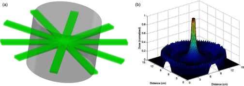
Illustration of overlapping concept. (a) Multiple MRT microbeam arrays from separate orthovoltage x-ray tubes overlapping in the center of a cylindrical phantom. (b) Simulated dose distribution showing how the weak penetration of orthovoltage x-rays may be mitigated by overlapping several microbeams. Diagrams shown here are for illustrative effect only and do not directly correspond to each other or to studies presented in this work.
Based on these considerations, the goals of this pilot study were to (1) demonstrate microbeam radiation using a sealed CNT x-ray tube that generates a diverging cone-beam instead of the nearly parallel beam from the synchrotron source; (2) evaluate the dose rate and dose distribution that can be obtained with a distributed source array; and (3) estimate the x-ray power needed to generate microbeam radiation with a workable dose rate for small animal radiation. The results provide a guideline for the design of a higher dose rate system using the distributed x-ray source array technology.
For this feasibility study, a low-power and low-energy microfocus x-ray tube mounted on a micro-CT scanner with a rotating gantry was used and a custom motorized microbeam collimator was designed. A distributed, circular source array configuration was simulated by rotating the x-ray tube around the gantry, and microbeams with widths of 300 μm and ∼10 peak-to-valley dose ratios at the center of the phantom were obtained. Finally, a total dose of 34 cGy was achieved with the x-ray tube operating at 50 kVp and 110 mAs of on-time.
MATERIALS AND METHODS
Micro-CT scanner
A pre-existing cone-beam micro-CT scanner is used as a low-power model of a rotating therapeutic x-ray source. It consists of a microfocus CNT field emission x-ray tube and a commercial flat panel x-ray detector (C7940DK-02, Hamamatsu) mounted on a rotating gantry as described in previous works.29, 32, 33 The x-ray tube produces an effective 100 μm isotropic focal spot as viewed through a 0.2 mm thick beryllium x-ray window. The anode was given a voltage of 50 kV, while the cathode was set at a duty cycle of 10% and current of 1 mA. Based on a previously measured cathode-gate transmission rate of 50% for this scanner,34 this translates to 0.05 mAs of tube current per cathode pulse.
For this set of experiments, the source to axis distance was increased to 16 cm from 12 cm to allow for the placement of a custom-made microbeam collimator alignment assembly described below. The noncollimated entrance dose rate was calculated to be 0.47 cGy/mAs at the increased source to axis distance, based upon a simple inverse-square correction and the previously measured dose rate of the scanner.32
Phantom construction and film measurement
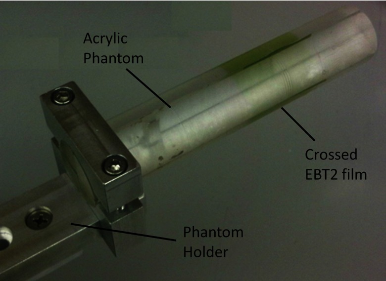
A specialized phantom and holder were designed that attached to the preexisting mouse stage (Velmex, Bloomfield, NY) of our micro-CT scanner, which is capable of micrometer precision in positioning. The phantom itself was constructed out of a 25 mm diameter, 127 mm long acrylic cylinder cut into four quadrants as shown in Fig. 2. Crossing Gafchromic XR-QA films (Ashland Advanced Materials, Covington, KY) were placed in the phantom for all qualitative experimentation listed below.
Figure 2.
Labeled photograph of phantom with crossed Gafchromic® EBT2 film sandwiched inside.
Films were scanned in a flatbed scanner (Epson V700) with an interpolated 2 μm resolution and dose profiles were attained by analyzing the data in ImageJ (National Institutes of Health). To attain dose profiles across the line patterns produced, microbeam lines were aligned orthogonally by image rotation and pixel values were averaged along a thick rectangle crossing and covering the beam pattern in question. These values were converted to net optical density (netOD) using the standard method,35 and then the netOD was plotted with position and labeled as relative dose using Microsoft Excel. No calibration curve for fitting optical density to dose was created because only relative dose profiles were needed for qualitative study.
For quantitative study, crossing Gafchromic EBT2 films (Ashland) were used instead of XR-QA due to the need to measure an absorbed dose outside the range of XR-QA. For dose readout of the EBT2 film, a dose calibration curve created for use in the CyberKnife® suite of the North Carolina Cancer Hospital was employed. After irradiation, the crossed films were removed from the phantom and sent to the hospital to be analyzed.
Collimator assembly
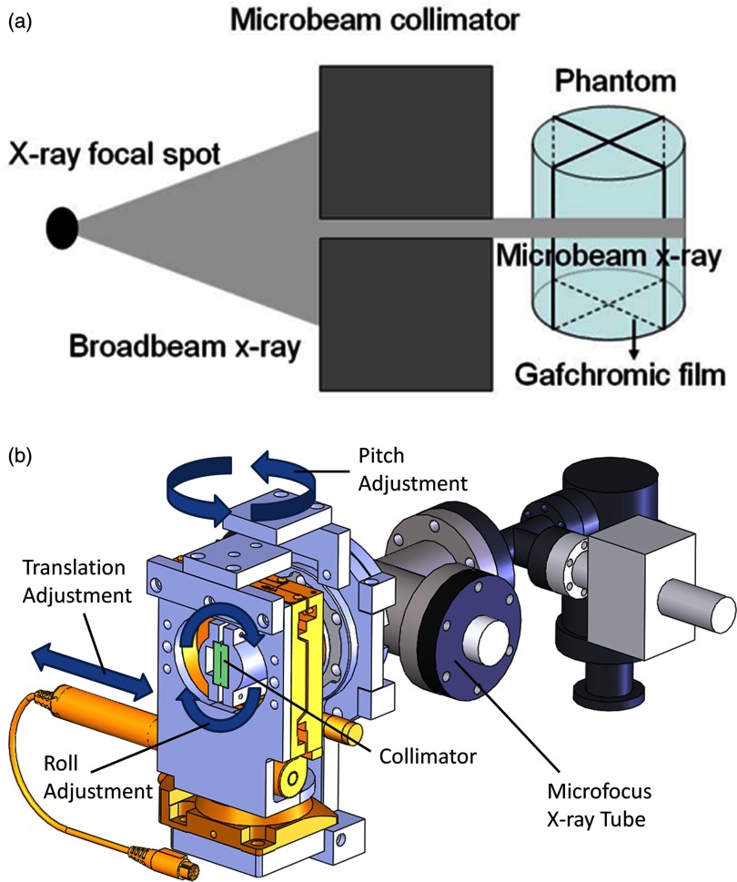
The cone beam radiation from the microfocus tube was collimated into a submillimeter fan beam, as illustrated in Fig. 3a, using a custom-made microbeam collimator affixed to the x-ray window of the micro-CT scanner as shown in Fig. 3b. This collimator was fashioned from two stainless steel gauge blocks (Mitutoyo, Japan) clamped together against two 220 μm glass spacers. The resulting collimator was 25 mm thick with a 25 mm long and 220 μm thick slit. The alignment system was designed with the ability to translate in a direction perpendicular to the plane of gantry rotation, pitch in a direction above and below the gantry plane, and roll around the axis of the cone beam, also as shown in Fig. 3b. Using these three degrees of freedom, the collimator was aligned in such a way to create a fan beam that would be precisely in the plane of gantry rotation regardless of gantry angle.
Figure 3.
(a) Diagram illustrating the process of microbeam irradiation using our microfocus x-ray tube. (b) SolidworksTM representation of the x-ray tube and collimator alignment assembly showing degrees of freedom necessary to select the appropriate collimation microplane that will coincide with the gantry's plane of rotation. (X-ray window not shown because it is covered by the alignment assembly.)
Microbeam creation
The translation stage (Model 426A with TRA25PPM actuator, Newport Corporation, Irvine, CA) was scanned through its range of motion to find the setting at which the focal spot was brightest as seen through the collimator by looking at its live image on the x-ray detector. After finding this initial position, a single strip of XR-QA film was irradiated from two opposing horizontal positions (which will be designated as 0° and 180° from here on) of the x-ray tube on the gantry, creating a crossed line pattern on the film. The angle between the crossed lines was noted and the roll angle was adjusted with the first rotation stage (Newport model RS-65 with SM-13 actuator). This process was repeated until there was no discernible angle between the lines created on the film, indicating proper alignment and beam overlap. A similar procedure employing an edge-on irradiation of film and an adjustment of the other rotation stage (Newport model RS-65 with NSA12 actuator) was used to align the pitch angle. During these initial alignment procedures, it was assumed and seen that the pitch and roll angular adjustments followed the small-angle approximation and thus were linearly independent.
After alignment, a 1.5 mm thick piece of lead with a 5 mm aperture was affixed to the exit side of the collimator to give the resultant microbeam a smaller length, creating a microbeam that diverged to become 6.5 mm × 300 μm at isocenter. As a final step, a 0.5 mm thick aluminum sheet was placed behind the collimator for beam filtration, giving the final emerging x-ray spectrum a median energy of 30 keV.36
EXPERIMENTAL PROCEDURES
Beam width measurement and overlap verification
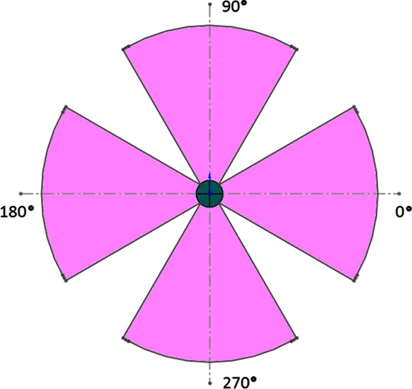
In order to verify microbeam overlap from multiple gantry positions, we elected to use entrance angles in four sections of 60°, each centered on one of the four main axes as shown in Fig. 4. Each of the four sections is separated into 11 different entry ports spaced evenly at 6° apart. Collimator adjustments were needed to account for initial misalignment of the vertical beams due to a small angular deflection in the gantry arm under the weight of the x-ray tube for the top and bottom sections. No such corrections were necessary for the right and left segments.
Figure 4.
Scale drawing of radiation pattern for overlap experiment. Incoming irradiation was evenly distributed within the four 60° sections shown using 11 separate entrance angles from each section. Four quadrant circle in the center represents the phantom and the outer arcs represent the path of the focal spot around the gantry isocenter.
Ten 0.05 mAs pulses were delivered from each entry port to accumulate enough dose on the film for suitable readout. After irradiation, the crossed films were removed from the phantom and scanned according to the procedures previously detailed. The scans were then analyzed for beam overlap and alignment by comparing the beam width with that of a beam incident from only one direction. Also, films were qualitatively examined for dose accumulation in the center of the phantom to show the feasibility of experimentally recreating results similar to those demonstrated in our previous simulation study.31
Peak to valley dose ratio
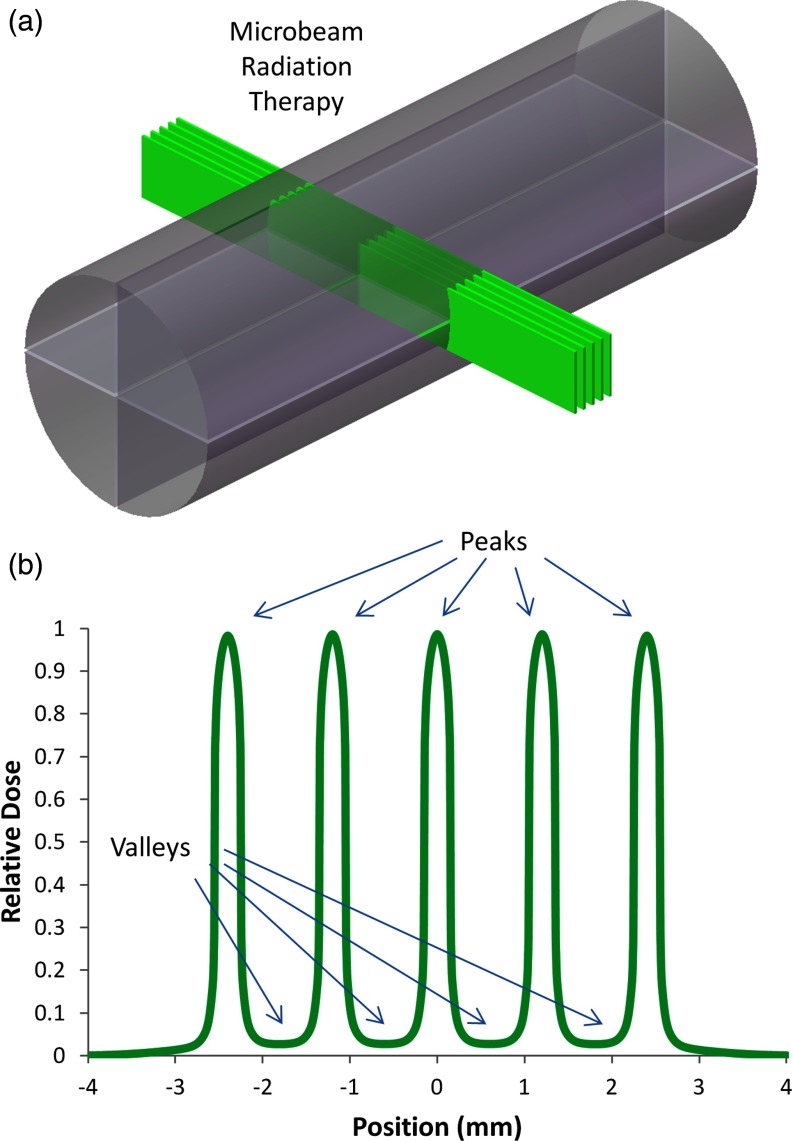
The peak to valley dose ratio (PVDR), as illustrated in Fig. 5b, has been shown to greatly affect the therapeutic ratio of MRT treatment.10, 37, 38 Therefore, we measured the PVDR at center-to-center beam spacings of 600, 900, and 1200 μm in order to determine which beam spacing would produce values of ∼10 for this parameter given our divergent source. For this experiment, only the 0° and 180° entrance angles were used. A pattern of five microbeams was delivered to the phantom and film as shown in Fig. 5a, each consisting of 120 pulses from each of the two opposing directions. The pattern was delivered by setting the gantry to the 0° angle, delivering the 120 pulses to the phantom, and then translating the phantom along its axis by the designated beam spacing after each set of pulses. The gantry was then rotated to the 180° angle and the steps of the first pattern were retraced, creating microbeams that would overlap with the first set of five beams. After irradiation, the film was scanned and the ratio between the average peak and valley doses was calculated for each of the three beam spacings.
Figure 5.
(a) In our setup, five x-ray microbeams are incident on a cylindrical plastic phantom from both sides. (b) Idealized dose distribution illustrating the characteristic high peaks and low valleys inherent to MRT dose distributions. As noted in the text, control of the PVDR is essential to retaining a high therapeutic ratio.
Interlacing beams demonstration
Due to the fact that synchrotron MRT research groups have begun to explore the efficacy of interlaced microbeams in the treatment of neurological disorders and brain tumors,12, 39, 40, 41, 42 the capability to interlace microbeams incident from different entrance angles was also demonstrated. This experiment used only the four main axes for entrance angles, giving 132 pulses of 0.05 mAs from each direction. The beams from the 0° and 180° directions were spaced by 900 μm center-to-center along the axis of the phantom and offset from the beams incident from the 90° and 270° angles by half this spacing. Five beams were incident from the 0° and 180° directions and interlaced with four beams incident from the 90° and 270° directions. The method of creating this spacing was similar to that described for the PVDR study above. Finally, the film was removed from the phantom, scanned, and qualitatively examined for interlacing capabilities.
Preliminary dose rate measurement
A quantitative dose experiment was performed to provide an extrapolated estimate for the capabilities of a full-scale device. This experiment was set up in the same manner as the qualitative overlap study above with the additional caveat that fifty 0.05 mAs pulses were given from each of the 44 entry angles instead of ten. After films were analyzed as described previously, the maximum dose measured at the center of the phantom was combined with proposed device specifications for our full-scale device to extrapolate an estimate of its projected dose rate. For this projection, the following relationship between the output power (P) of an x-ray tube and its operational parameters was used.
| (1) |
This proportionality was derived from the standard equation for the total unfiltered radiant energy from the bremsstrahlung spectrum of a reflective anode type x-ray tube.43 In this equation, V refers to the anode voltage which accelerates the electrons toward the reflective target, I represents the amount of electron current from the cathode that impinges on the anode target to create x-rays, and Z is the atomic number of this anode target material.
RESULTS
Beam width measurement and overlap verification
After initial collimator alignment, it was observed that the combined beam width of two opposing overlapped beams as marked on film was 290 ± 30 μm. The width of a single nonoverlapped beam at the isocenter of the micro-CT scanner was calculated to be around 300 ± 20 μm using geometric considerations. From these measurements, it can be concluded that the overlap of the two beams is coincidental to within the intrinsic error of our measurement technique. It was also observed that the width of the overlapped beams as marked on film does not display additional widening at the edges of the phantom, indicating that the beams do not merely cross at the isocenter, but rather overlap through the entirety of their transmission through the phantom.
During the experiment in which microbeams were overlapped from 44 different entrance angles, the FWHM of the resulting beam was 300 μm, as shown in Fig. 6b. This was only 3.4% wider than the measurement only involving two opposing beams described above. In addition, the beam width near the edges of the phantom still displayed the same width as a single beam. As shown in Fig. 6c, which represents a measurement of dose along the beam path in the vertical direction, relative dose in the center of the phantom was measured to be roughly two times higher than dose in the surrounding material.
Figure 6.
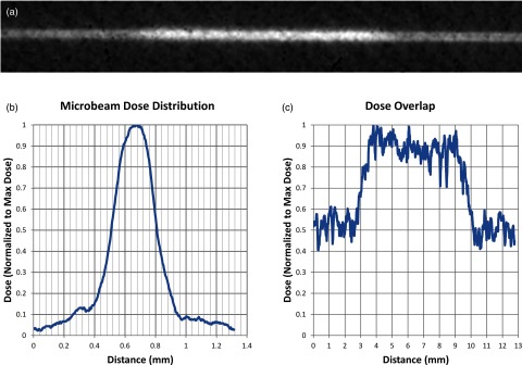
Results of the overlap experiment showing (a) the inverted grayscale image of the vertical irradiated film, (b) a graph of relative dose displaying the dose profile along the width of the overlapped microbeams, and (c) a graph of the dose along the length of the irradiated line displaying roughly double the dose in the center of the phantom than in the peripheral areas.
Peak to valley dose ratio
During the PVDR study, center-to-center beam separations of 600, 900, and 1200 μm respectively produced PVDRs of 5.1, 8.6, and 9.6 at the center of the phantom as shown in the film scans from the PVDR study displayed in Fig. 7, with results listed in Table 1. Due to a considerable amount of signal noise in the valley for the 1200 μm case, it was necessary to average the dose within this region rather than simply use the minimum to calculate PVDR. To do this, the valley region was defined to be anywhere between two peaks where the dose was less than D10 as defined below.
| (2) |
In this formula, represents the average minimum dose in the valleys and represents the average peak dose. Also using this formulation, a valley width for each of the three spacings was calculated using the D10 positions within the distributions. These were calculated to be 190, 450, and 620 μm and are also displayed in Table 1.
Figure 7.
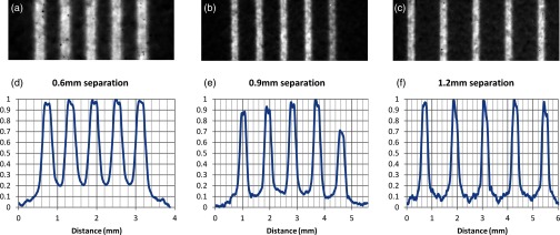
Films and dose profiles of microbeams delivered with different center to center (c-t-c) spacings. Vertical axes in graphs (d)–(f) represent relative dose (normalized to the maximum dose). Film (a) and profile (d) of 290 μm microbeams delivered at 600 μm c-t-c spacing. Film (b) and profile (e) of similar beams delivered at 900 μm spacing. Note that there was an error in delivery in the fifth beam so only the previous four were used in the PVDR and valley width calculations. Film (c) and profile (f) of beams delivered at 1200 μm spacing. Also note the higher noise level in the valley at the largest c-t-c spacing, indicating the possibility of a lack of measurable dose in this region.
Table 1.
PVDR and valley width for various center-to-center beam separations of our microbeams. Microbeams had FWHM values of 300 μm. All results here are averaged over all peaks (or valleys) in the array.
Center to center.
Modified PVDR value that uses average relative dose across the valley regions to mitigate noise in the signal.
Interlacing beams demonstration
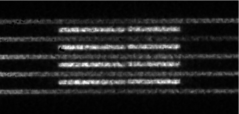
In this study, we were successful in placing one pattern inside the other (as shown in Fig. 8), thus creating a dose pattern that was a well-defined microbeam distribution outside the target area, but that delivered twice the density of dose inside the target area, effectively doubling the dose volume. As a side note, it can be seen from the film that beams incident from the direction parallel to the film produce less signal than perpendicularly incident beams even though the same amount of beam on time was used. This inconsistency was to be expected, though, since numerous studies have reported conflicting results on film behavior when it is irradiated parallel to the film plane as opposed to perpendicularly.44, 45, 46 Therefore, a relative dose profile for this film is excluded from this work.
Figure 8.
Scanned image of film in which beams were overlapped from opposing directions and interlaced in perpendicular directions. Dose volume was doubled in the target region while surrounding regions only see a typical microbeam pattern. The relative dose profile for this film has been omitted because of inconsistencies in film response when beams are incident edge-on to the film.
Preliminary dose rate measurement
The peak dose measured by the EBT2 film in our quantitative measurement was 34 cGy and the FWHM was found to be identical to that shown above. Using the previously measured dose rate of the micro-CT tube and assuming nearly ideal dose accumulation from the overlapping microbeams, the 2200 pulses of 0.05 mAs each should have resulted in a dose of 52 cGy with no attenuation. When accounting for the attenuation of the 1.25 cm of acrylic with tabulated mass attenuation coefficients47 at our median x-ray energy of 30 keV, however, the expected dose value for this experiment is found to be 33 cGy, which compares well with the measured value and again indicates good overlap and collimator transmission.
Finally as can be seen in Table 2, this measurement for the micro-CT setup corresponds to an instantaneous dose rate of 0.00154 Gy/s or 3.1 Gy/As. Therefore, based on the preliminary specifications of the proposed compact CNT MRT device (also as seen in Table 2) and an extrapolation based on the use of Eq. 1 as described above, an instantaneous dose rate of 100 Gy/s should be achievable given an anode current of around 1 A, an anode voltage of 160 kV, an anode target material made from tungsten, and a source to target distance of 12 cm.
Table 2.
Calculation of the necessary tube current (A) to achieve 100Gy/s (dose rate) in the prototype device based upon the measured MRT dose rate using the micro-CT scanner. Note that the different configuration source distances necessitate an inverse-square correction in addition to those indicated in the text.
| Device configuration | Tube current | Anode voltage (kV) | Anode material (Z) | Source distance (cm) | Dose rate (Gy/s) |
|---|---|---|---|---|---|
| Micro-CT | 0.5 mA | 50 | Mo (42) | 16 | 0.00154 |
| Prototype | 1.0 A | 160 | W (74) | 12 | 100 |
DISCUSSION
As was seen from the results of initial alignment and the overlap of collimated microbeams from opposing angles, the machinery designed for this work proved quite capable of creating microbeams from our CNT x-ray source and superimposing them within the target. In regards to the experiment in which multiple entrance angles were used, the achieved alignment was better than expected based upon on the previously imperceptible deformation of the plane of rotation under the weight of the x-ray source. It was also noted that the beam width remained fairly constant even outside the target region, indicating that beam alignment was not only sufficient to provide overlap within the target region, but also to maintain the integrity of a delivered microbeam array outside the target region. This is an ability that will be essential to sparing normal tissue surrounding targeted tumors in MRT treatments.
Although the data on beam width and alignment is quite conclusive, results involving the dose addition in the target region where beams were overlapped must only be considered qualitatively due to the nature of our setup. Various studies have shown that discrepancies in quantitative analysis can arise when irradiating film in an orientation parallel to the beam path and sandwiching film in plastic phantoms with possible air gaps.44, 45, 46 Therefore, even though the film showed an increase in measurable signal within the targeted region when compared to the signal in the periphery of the phantom, how much of a corresponding increase in dose is unknown because half of the irradiation was delivered perpendicular to the film while the other half was incident edge-on. Therefore, this study cannot be used as a quantitative result to compare with simulations done in earlier work, both because of this lack of reliable quantitative data and large differences in experimental setup.31 Regardless, it does show that achieving a microbeam dose within the target region of a small irradiated subject that is higher than the dose at its periphery is possible with methods of alignment such as those shown here.
After an analysis of the results from the PVDR study, a beam width to separation distance ratio of approximately 1:4 for future designs was decided upon due to this configuration's average valley width of 620 μm and PVDR of 9.6. We considered this to be the minimum value for PVDR, with the valley widths and PVDR values of the other configurations deemed to be too small to allow for normal tissue repair when giving peak doses on the order of 100s of Gy based upon studies done at synchrotron facilities.7, 10, 48 The reason our PVDR is lower than those measured in synchrotron studies that employ similar beam widths but smaller beam separations12, 39, 40 is clearly due to the divergent nature of our beam. In addition to the fact that this divergence causes a non-negligible increase of beam size in both the length and width as the beam penetrates the target region, it will also produce much more collimator scatter before the target region is even reached. This will in turn increase valley dose beyond what is seen from the quasi-parallel beams produced at synchrotron sites49 and subtract from peak dose. Therefore, a larger beam separation is warranted and necessary when using a divergent source.
The qualitative study on interlacing capabilities further highlighted the utility of our collimation system and micro-focus x-ray tube by demonstrating its ability to construct micrometrically accurate dose distributions within the target region of the phantom. In this way, a table-top system of this type could create microbeam distributions such as those seen in various synchrotron studies that overlap, interlace, or cross in the target region to increase the peak dose and/or the valley dose given to the target.9, 40, 41, 42 Moreover, this experiment displayed the conjunction of microbeam overlap with interlacing. Expanding this concept to multiple gantry angles on a larger phantom would allow for the possibility of simultaneously producing a maximum continuous dose distribution at the target while leaving a lower-dose, microbeam dose distribution in the surrounding regions by using a fraction of the angles for overlap and the remaining fraction for interlacing. In this way, both dose magnitude and volume can be increased at the target.
Finally, we have demonstrated that we should be able to scale-up to a device with a power high enough to deliver effective MRT doses (100s of Gy) in a reasonable time scale, given the 160 kV anode voltage and compact sizes achievable using our CNT cathode devices.50 It should be noted that even at the projected dose rate of 100 Gy/s, physiological gating as shown by Cao et al.32 may still be necessary if cardiosynchronous motion of the cerebral microvasculature is strong enough to blur the microbeam pattern. Even if such gating reduces the effective dose rate by 20x, though, a microbeam pattern with five beams, each with a depth dose of 600 Gy would still be possible within 10 min given a single distributed line source with a 100 Gy/s instantaneous dose rate. Moreover, given the preliminary device specifications above, the dose rate will likely be even higher, seeing as how our rudimentary extrapolation was based upon depth dose, which would increase appreciably at 160 kVp.
Such a device will be tenable through the use of our CNT source arrays to spread the anode heat load necessary for such a high dose rate into a large enough focal area. Based on the results of this study, it is feasible to align microbeams created from a single divergent source and collimator into a single microplane in the target region. Therefore, the concept of surrounding a target with multiple small line sources and collimating the set of axially symmetric microbeams all into a single plane, also as described by Schreiber et al.,31 will also be possible. This will allow for the large anode area needed to dissipate the amount of heat that will be created from over an amp of anode current. Similar to the typical x-ray tube design in which a rotating anode spreads the heat from one focal spot around a full circle of the anode to create a highly luminous single source, this design would also spread the heat across a large circular path. But in this case, the path would be much larger because it would encompass the irradiation target, not require rotation, and make use of a large number of much weaker sources to create a much more favorable dose distribution in the subject.
CONCLUSIONS
It has been shown here that microbeam dose profiles can be created from a microfocus x-ray tube with the addition of a precise collimator alignment system. In addition, the possibility of microbeam overlap from various entrance angles has been demonstrated. Experimentation on how PVDR varies with beam separation given a divergent beam has also been achieved, providing a starting point for future research on MRT from divergent sources. Moreover, the precision of the collimation and alignment system demonstrated here also highlights the capability of beam interlacing within the target region of interest.
We have also demonstrated the feasibility of creating a compact device capable of delivering microbeam dose distributions without the use of a synchrotron source by incorporating many of our CNT x-ray sources in tandem. These dose distributions based upon our circular geometry will provide a much lower entrance dose than that seen at synchrotron sites while retaining their microplanar structure. Simultaneously, such a design will allow for dose rates high enough to create therapeutic microbeam doses in small animal studies using a table-top source. It is our greatest hope that the resulting increase in availability of MRT radiobiological studies will help uncover more of the mechanisms behind the high therapeutic ratios of MRT as demonstrated in small animals and possibly open new avenues to be explored through which this promising new technique could be brought to future patients.
ACKNOWLEDGMENTS
This work was supported by the North Carolina Translational and Clinical Sciences Institute (Award No. UL1RR025747 from the National Center for Research Resources) and the National Institutes of Health Grand Opportunities “GO” program (Grant No. RC2-CA148487). The authors would like to thank Christy Inscoe for her help with shielding during experimentation with the mobile micro-CT scanner, Dr. Xin Qian for helpful discussions in setting up the experiment, and Dr. Xiomara Calderon-Colon and Dr. Shabana Sultana for their hard work in optimizing the CNT cathodes and focusing structure of the x-ray source.
References
- Van Dyk J., The Modern Technology of Radiation Oncology: A Compendium for Medical Physicists and Radiation Oncologists (Medical Physics Publishing, Madison, WI, 1999). [Google Scholar]
- Van Dyk J., The Modern Technology of Radiation Oncology, Volume 2: A Compendium for Medical Physicists and Radiation Oncologists (Medical Physics Publishing, Madison, WI, 2005). [Google Scholar]
- Zeman W., Curtis H. J., and Baker C. P., “Histopathologic effect of high-energy-particle microbeams on the visual cortex of the mouse brain,” Radiat. Res. 15, 496–514 (1961). 10.2307/3571293 [DOI] [PubMed] [Google Scholar]
- Slatkin D. N., Spanne P., Dilmanian F. A., and Sandborg M., “Microbeam radiation therapy,” Med. Phys. 19, 1395–1400 (1992). 10.1118/1.596771 [DOI] [PubMed] [Google Scholar]
- Laissue J. A., Lyubimova N., Wagner H.-P., Archer D. W., Slatkin D. N., Di Michiel M., Nemoz C., Renier M., Brauer E., Spanne P. O., Gebbers J.-O., Dixon K., and Blattmann H., “Microbeam radiation therapy,” Proc. SPIE 3770, 38–45 (1999). 10.1117/12.368185 [DOI] [Google Scholar]
- Slatkin D. N., Spanne P., Dilmanian F. A., Gebbers J. O., and Laissue J. A., “Subacute neuropathological effects of microplanar beams of x-rays from a synchrotron wiggler,” Proc. Natl. Acad. Sci. U.S.A. 92, 8783–8787 (1995). 10.1073/pnas.92.19.8783 [DOI] [PMC free article] [PubMed] [Google Scholar]
- Laissue J. A., Blattmann H., Di Michiel M., Slatkin D. N., Lyubimova N., Guzman R., Zimmermann W., Birrer S., Bley T., Kircher P., Stettler R., Fatzer R., Jaggy A., Smilowitz H., Brauer E., Bravin A., Le Duc G., Nemoz C., Renier M., Thomlinson W. C., Stepanek J., and Wagner H.-P., “Weanling piglet cerebellum: A surrogate for tolerance to MRT (microbeam radiation therapy) in pediatric neuro-oncology,” Proc. SPIE 4508, 65–73 (2001). 10.1117/12.450774 [DOI] [Google Scholar]
- Dilmanian F. A., Morris G. M., Le Duc G., Huang X., Ren B., Bacarian T., Allen J. C., Kalef-Ezra J., Orion I., Rosen E. M., Sandhu T., Sathé P., Wu X. Y., Zhong Z., and Shivaprasad H. L., “Response of avian embryonic brain to spatially segmented x-ray microbeams,” Cell. Mol. Biol. 47, 485–493 (2001). [PubMed] [Google Scholar]
- Laissue J. A., Geiser G., Spanne P. O., Dilmanian F. A., Gebbers J.-O., Geiser M., Wu X.-Y., Makar M. S., Micca P. L., Nawrocky M. M., Joel D. D., and Slatkin D. N., “Neuropathology of ablation of rat gliosarcomas and contiguous brain tissues using a microplanar beam of synchrotron-wiggler-generated X rays,” Int. J. Cancer 78, 654–660 (1998). [DOI] [PubMed] [Google Scholar]
- Dilmanian F. A., Button T. M., Le Duc G., Zhong N., Pena L. A., Smith J. A. L., Martinez S. R., Bacarian T., Tammam J., Ren B., Farmer P. M., Kalef-Ezra J., Micca P. L., Nawrocky M. M., Niederer J. A., Recksiek F. P., Fuchs A., and Rosen E. M., “Response of rat intracranial 9L gliosarcoma to microbeam radiation therapy,” Neurooncology 4, 26–38 (2002). [DOI] [PMC free article] [PubMed] [Google Scholar]
- Laissue J. A., Blattmann H., Wagner H. P., Grotzer M. A., and Slatkin D. N., “Prospects for microbeam radiation therapy of brain tumours in children to reduce neurological sequelae,” Dev. Med. Child Neurol. 49, 577–581 (2007). 10.1111/j.1469-8749.2007.00577.x [DOI] [PubMed] [Google Scholar]
- Prezado Y., Sarun S., Gil S., Deman P., Bouchet A., and Le Duc G., “Increase of lifespan for glioma-bearing rats by using minibeam radiation therapy,” J. Synchrotron. Radiat. 19, 60–65 (2012). 10.1107/S0909049511047042 [DOI] [PubMed] [Google Scholar]
- Crosbie J. C., Anderson R. L., Rothkamm K., Restall C. M., Cann L., Ruwanpura S., Meachem S., Yagi N., Svalbe I., Lewis R. A., Williams B. R., and Rogers P. A., “Tumor cell response to synchrotron microbeam radiation therapy differs markedly from cells in normal tissues,” Int. J. Radiat. Oncol., Biol., Phys. 77, 886–894 (2010). 10.1016/j.ijrobp.2010.01.035 [DOI] [PubMed] [Google Scholar]
- Bouchet A., Lemasson B., Le Duc G., Maisin C., Brauer-Krisch E., Siegbahn E. A., Renaud L., Khalil E., Remy C., Poillot C., Bravin A., Laissue J. A., Barbier E. L., and Serduc R., “Preferential effect of synchrotron microbeam radiation therapy on intracerebral 9L gliosarcoma vascular networks,” Int. J. Radiat. Oncol., Biol., Phys. 78, 1503–1512 (2010). 10.1016/j.ijrobp.2010.06.021 [DOI] [PubMed] [Google Scholar]
- Stepanek J., Blattmann H., Laissue J. A., Lyubimova N., Di Michiel M., and Slatkin D. N., “Physics study of microbeam radiation therapy with PSI-version of Monte Carlo code GEANT as a new computational tool,” Med. Phys. 27, 1664–1675 (2000). 10.1118/1.599034 [DOI] [PubMed] [Google Scholar]
- De Felici M., Felici R., del Rio M. S., Ferrero C., Bacarian T., and Dilmanian F. A., “Dose distribution from x-ray microbeam arrays applied to radiation therapy: An EGS4 Monte Carlo study,” Med. Phys. 32, 2455–2463 (2005). 10.1118/1.1951043 [DOI] [PubMed] [Google Scholar]
- Siegbahn E. A., Stepanek J., Bräuer-Krisch E., and Bravin A., “Determination of dosimetrical quantities used in microbeam radiation therapy (MRT) with Monte Carlo simulations,” Med. Phys. 33, 3248–3259 (2006). 10.1118/1.2229422 [DOI] [PubMed] [Google Scholar]
- Tu S.-J., Hsieh H.-L., Chao T.-C., and Lee C.-C., “Feasibility of using the micro CT imaging system as the conformal radiation therapy facility for small animals,” Proc. SPIE 7258, 72585T-1–72585T-8 (2009). 10.1117/12.813598 [DOI] [Google Scholar]
- Wong J., Armour E., Kazanzides P., Iordachita I., Tryggestad E., Deng H., Matinfar M., Kennedy C., Liu Z., Chan T., Gray O., Verhaegen F., McNutt T., Ford E., and DeWeese T. L., “High-resolution, small animal radiation research platform with x-ray tomographic guidance capabilities,” Int. J. Radiat., Oncol., Biol., Phys. 71, 1591–1599 (2008). 10.1016/j.ijrobp.2008.04.025 [DOI] [PMC free article] [PubMed] [Google Scholar]
- Izaguirre E. W., Kassebaum B. L., Birch J., Su I. T., Goddu S. M., and Low D. A., “Development of a High Resolution Image Guided Microirradiator,” presented at the Nuclear Science Symposium Conference Record (NSS/MIC), IEEE2009, 2009, Institute of Electrical and Electronics Engineers (IEEE), pp. 2690–2693.
- Verhaegen F., Granton P., and Tryggestad E., “Small animal radiotherapy research platforms,” Phys. Med. Biol. 56, R55–R83 (2011). 10.1088/0031-9155/56/12/R01 [DOI] [PubMed] [Google Scholar]
- Huang K., Yan K., Podder T., Hu Y., and Yu Y., presented at the AAPM Annual Meeting, Anaheim, CA, 2009. (unpublished).
- Zhou O. Z. and Chang S. X., “Compact Microbeam Radiation Therapy Systems and Methods for Cancer Treatment and Research,” U.S. patent 8,600,003 B2 (3 December 2013).
- Bordelon D. E., Zhang J., Graboski S., Cox A., Schreiber E., Zhou O. Z., and Chang S., “A nanotube based electron microbeam cellular irradiator for radiobiology research,” Rev. Sci. Instrum. 79, 125102 (2008). 10.1063/1.3043417 [DOI] [PMC free article] [PubMed] [Google Scholar]
- Wang S., Calderon X., Peng R., Schreiber E. C., Zhou O., and Chang S., “A carbon nanotube field emission multipixel x-ray array source for microradiotherapy application,” Appl. Phys. Lett. 98, 213701 (2011). 10.1063/1.3595268 [DOI] [PMC free article] [PubMed] [Google Scholar]
- Maltz J. S., Sprenger F., Fuerst J., Paidi A., Fadler F., and Bani-Hashemi A. R., “Fixed gantry tomosynthesis system for radiation therapy image guidance based on a multiple source x-ray tube with carbon nanotube cathodes,” Med. Phys. 36, 1624–1636 (2009). 10.1118/1.3110067 [DOI] [PubMed] [Google Scholar]
- Qian X., Tucker A., Gidcumb E., Shan J., Yang G., Calderon-Colon X., Sultana S., Lu J., Zhou O., Spronk D., Sprenger F., Zhang Y., Kennedy D., Farbizio T., and Jing Z., “High resolution stationary digital breast tomosynthesis using distributed carbon nanotube x-ray source array,” Med. Phys. 39, 2090–2099 (2012). 10.1118/1.3694667 [DOI] [PMC free article] [PubMed] [Google Scholar]
- Zhou O. and Calderon-Colon X., “Carbon nanotube-based field emission x-ray technology,” in Carbon Nanotube and Related Field Emitters, edited by Saito Y. (John Wiley & Sons, Hoboken, NJ, 2010), pp. 417–437. [Google Scholar]
- Cao G., Lee Y. Z., Peng R., Liu Z., Rajaram R., Calderon-Colon X., An L., Wang P., Phan T., Sultana S., Lalush D. S., Lu J. P., and Zhou O., “A dynamic micro-CT scanner based on a carbon nanotube field emission x-ray source,” Phys. Med. Biol. 54, 2323–2340 (2009). 10.1088/0031-9155/54/8/005 [DOI] [PubMed] [Google Scholar]
- Lee Y. Z., Burk L. M., Wang K. H., Cao G., Volmer J., Lu J., and Zhou O., “Prospective respiratory gated carbon nanotube micro computed tomography,” Acad. Radiol. 18, 588–593 (2011). 10.1016/j.acra.2010.11.022 [DOI] [PMC free article] [PubMed] [Google Scholar]
- Schreiber E. C. and Chang S. X., “Monte Carlo simulation of a compact microbeam radiotherapy system based on carbon nanotube field emission technology,” Med. Phys. 39, 4669–4678 (2012). 10.1118/1.4728220 [DOI] [PMC free article] [PubMed] [Google Scholar]
- Cao G., Burk L. M., Lee Y. Z., Calderon-Colon X., Sultana S., Lu J., and Zhou O., “Prospective-gated cardiac micro-CT imaging of free-breathing mice using carbon nanotube field emission x-ray,” Med. Phys. 37, 5306–5312 (2010). 10.1118/1.3491806 [DOI] [PMC free article] [PubMed] [Google Scholar]
- Liu Z., Yang G., Lee Y. Z., Bordelon D., Lu J., and Zhou O., “Carbon nanotube based microfocus field emission x-ray source for microcomputed tomography,” Appl. Phys. Lett. 89, 103111 (2006). 10.1063/1.2345829 [DOI] [Google Scholar]
- Sultana S., Calderón-Colón X., Cao G., Zhou O., and Lu J., “Design and characterization of a carbon-nanotube-based micro-focus x-ray tube for small animal imaging,” Proc. SPIE 7622, 76225G-1–76225G-9 (2010). 10.1117/12.844350 [DOI] [Google Scholar]
- Devic S., Seuntjens J., Sham E., Podgorsak E. B., Schmidtlein C. R., Kirov A. S., and Soares C. G., “Precise radiochromic film dosimetry using a flat-bed document scanner,” Med. Phys. 32, 2245–2253 (2005). 10.1118/1.1929253 [DOI] [PubMed] [Google Scholar]
- Burk L., “Development of a Carbon Nanotube-Based Micro-CT and its Applications in Preclinical Research,” (University Microfilms International (UMI) or Proquest LLC, Ann Arbor, MI, 2013), p. 173.
- Regnard P., Le Duc G., Brauer-Krisch E., Tropres I., Siegbahn E. A., Kusak A., Clair C., Bernard H., Dallery D., Laissue J. A., and Bravin A., “Irradiation of intracerebral 9L gliosarcoma by a single array of microplanar x-ray beams from a synchrotron: Balance between curing and sparing,” Phys. Med. Biol. 53, 861–878 (2008). 10.1088/0031-9155/53/4/003 [DOI] [PubMed] [Google Scholar]
- Serduc R., Bouchet A., Bräuer-Krisch E., Laissue J. A., Spiga J., Sarun S., Bravin A., Fonta C., Renaud L., Boutonnat J., Siegbahn E. A., Estève F., and Le Duc G., “Synchrotron microbeam radiation therapy for rat brain tumor palliation—Influence of the microbeam width at constant valley dose,” Phys. Med. Biol. 54, 6711–6724 (2009). 10.1088/0031-9155/54/21/017 [DOI] [PubMed] [Google Scholar]
- Prezado Y., Renier M., and Bravin A., “A New Synchrotron Radiotherapy Technique with Future Clinical Potential: Minibeams Radiation Therapy,” in World Congress on Medical Physics and Biomedical Engineering, Munich, Germany, 7–12 September 2009, edited by Dössel O. and Schlegel W. (Springer, Berlin, 2009), vol. 25/1, pp. 29–32. [Google Scholar]
- Dilmanian F. A., Zhong Z., Bacarian T., Benveniste H., Romanelli P., Wang R., Welwart J., Yuasa T., Rosen E. M., and Anschel D. J., “Interlaced x-ray microplanar beams: A radiosurgery approach with clinical potential,” Proc. Natl. Acad. Sci. U.S.A. 103, 9709–9714 (2006). 10.1073/pnas.0603567103 [DOI] [PMC free article] [PubMed] [Google Scholar]
- Serduc R., Bräuer-Krisch E., Siegbahn E. A., Bouchet A., Pouyatos B., Carron R., Pannetier N., Renaud L., Berruyer G., Nemoz C., Brochard T., Rémy C., Barbier E. L., Bravin A., Le Duc G., Depaulis A., Estève F., and Laissue J. A., “High-precision radiosurgical dose delivery by interlaced microbeam arrays of high-flux low-energy synchrotron X-rays,” PLoS One 5, e9028-1–e9028-12 (2010). 10.1371/journal.pone.0009028 [DOI] [PMC free article] [PubMed] [Google Scholar]
- Bräuer-Krisch E., Requardt H., Régnard P., Corde S., Siegbahn E., LeDuc G., Brochard T., Blattmann H., Laissue J., and Bravin A., “New irradiation geometry for microbeam radiation therapy,” Phys. Med. Biol. 50, 3103–3111 (2005). 10.1088/0031-9155/50/13/009 [DOI] [PubMed] [Google Scholar]
- Attix F. H., Introduction to Radiological Physics and Radiation Dosimetry (John Wiley & Sons, Hoboken, NJ, 1986). [Google Scholar]
- Suchowerska N., Hoban P., Butson M., Davison A., and Metcalfe P., “Directional dependence in film dosimetry: Radiographic and radiochromic film,” Phys. Med. Biol. 46, 1391–1397 (2001). 10.1088/0031-9155/46/5/305 [DOI] [PubMed] [Google Scholar]
- Suchowerska N., Hoban P., Davison A., and Metcalfe P., “Perturbation of radiotherapy beams by radiographic film: Measurements and Monte Carlo simulations,” Phys. Med. Biol. 44, 1755–1765 (1999). 10.1088/0031-9155/44/7/314 [DOI] [PubMed] [Google Scholar]
- Srivastava R. P. and De Wagter C., “The effects of incidence angle on film dosimetry and their consequences in IMRT dose verification,” Med. Phys. 39, 6129–6138 (2012). 10.1118/1.4752236 [DOI] [PubMed] [Google Scholar]
- Hubbell J. H. and Seltzer S. M., “Tables of x-ray mass attenuation coefficients and mass energy-absorption coefficients from 1 keV to 20 MeV for elements Z = 1 to 92 and 48 additional substances of dosimetric interest,” The National Institute of Standards and Technology (NIST) Report NISTIR 5632, 1995.
- Anschel D. J., Bravin A., and Romanelli P., “Microbeam radiosurgery using synchrotron-generated submillimetric beams: A new tool for the treatment of brain disorders,” Neurosurg. Rev. 34, 133–142 (2010). 10.1007/s10143-010-0292-3 [DOI] [PubMed] [Google Scholar]
- Nettelbeck H., Takacs G. J., Lerch M. L. F., and Rosenfeld A. B., “Microbeam radiation therapy: A Monte Carlo study of the influence of the source, multislit collimator, and beam divergence on microbeams,” Med. Phys. 36, 447–456 (2009). 10.1118/1.3049786 [DOI] [PubMed] [Google Scholar]
- Sprenger F., Calderon-Colon X., Cheng Y., Englestad K., Lu J., Maltz J., Paidi A., Qian X., Spronk D., Sultana S., Yang G., and Zhou O., “Distributed source x-ray tube technology for tomosynthesis imaging,” Proc. SPIE 7622, 76225M-1–76225M-8 (2010). 10.1117/12.844586 [DOI] [PMC free article] [PubMed] [Google Scholar]


