

SUMMARY
Live imaging technology has significantly advanced the field of neural injury and axon degeneration; however, studies are still predominantly performed in in vitro settings such as cultured neuronal cells or in lower model organisms such as C. elegans where axons lack glial wrappings. We recently developed a new in vivo model for adult-stage neural injury in the powerful model organism Drosophila melanogaster, using the highly accessible wing of the animal. Because the Drosophila wing is translucent and dispensable for survival, it allows clear and direct visualization of injury-induced progressive responses of axons and glia highlighted by fluorescent protein markers on live animals over time. Moreover, unlike previous Drosophila models of neural injury, this procedure does not require dissection of the central nervous system (CNS). Thus, the key preparation steps for in vivo imaging of neural injury response described in this protocol can be completed within 30 min.
INTRODUCTION
The consequence of neural injury such as spinal cord injury (SCI) and traumatic brain injury (TBI) in human patients is devastating and often leads to long-term disability and paralysis1,2. Understanding the mechanisms of injury-induced axon degeneration—namely, Wallerian degeneration—as well as glial, inflammatory and immune responses is central to the development of effective therapeutics. Because of the significant importance and the equally, if not more, significant challenges due to the complexity of the mammalian central nervous system (CNS), the molecular and cellular mechanisms of axon degeneration and regeneration have been the subject of intensive investigation for over a century. Such studies have long been conducted in vertebrate model organisms such as rodents3 and fish4, while recent insights have come from invertebrate animal models of neural injury such as Caenorhabditis elegans5 and Drosophila melanogaster6.
The discovery of fluorescent proteins (FP), the advancement of live cell imaging technology, and the development of super-resolution microscopy have dramatically advanced the field of cell biology especially for the study of cellular dynamics7. In addition, they have enabled neurobiologists to study axon injury and neurodegeneration by in vitro cell culture assays and ex vivo brain slices8,9. In order to fully understand the underlying mechanisms of axon degeneration and the poor capability of axon regeneration, however, in vivo imaging and study of neural injury-induced responses in intact animals is needed. Although difficult in rodent models, in vivo imaging of the nervous system for injury-related research has been developed in C. elegans10–12 and more recently in the adult Drosophila by our laboratory13. Because of superior optical advantages, the wing allows direct visualization of the FP-highlighted wing nerve in live animals (Fig. 1), which makes this system suitable for large-scale screening and adaptable to super-resolution microscopy. Here, we describe the detailed protocol for performing precise and reproducible axotomy of the adult Drosophila wing nerve and in vivo imaging of the injury responses without the need of time-consuming CNS surgery or dissection.
Figure 1. The neuronal and glial components of the Drosophila wing.

Using a dual labeling approach, (a) the neuronal (red, highlighted by appl-GAL4>UAS-mCD8-ChRFP) and (b) the glial (green, highlighted by repo-LexA::GAD> LexAop-rCD2-GFP) components of the wing nerve are readily visualized. (c) Merge of the red and green channels with a bright field image showing the overall morphology of the wing. The drivers illustrated here highlight all neurons (appl-GAL4) and all glia (repo-LexA::GAD), thus the wing nerve along the entire wing margin (the L1 vein and the costal vein), as well as along the L3 vein are labeled. Scale bar: 100 μm
Development of the protocol
The fly Drosophila is a genetically tractable model organism and has been proven highly successful for addressing a wide variety of complex biological questions that share evolutionarily conserved mechanisms with humans 14–17. Because of the simplicity and the vast molecular genetic tools available in Drosophila, fly geneticists have tried to model neural injury in Drosophila to study axon degeneration and regeneration (for a recent review, see6). Existing models include stabbing a needle through the fly head for massive TBI18, removing the olfactory organ to induce degeneration of the residual olfactory nerve in the brain19,20, cutting axons in brain explants with a microdissector21, and crushing or laser ablating axons in fly larvae22,23. However, none of these models allow direct visualization of the nervous system in adult animals, in which monitoring neural injury responses and evaluating potential therapeutic targets still require complicated, delicate, and time-consuming dissection. As a result, such procedures are challenging for large-scale molecular genetic screening, which is one of the most desirable approaches to identify novel genes, pathways, and unknown or unappreciated mechanisms that impact axon degeneration and regeneration.
To employ the full power of Drosophila genetics in the study of neural injury and axon degeneration, we sought to develop a new approach whereby axons could be directly visualized when highlighted with FP. Such a paradigm would allow precise axotomy and in vivo imaging of neural injury responses with a few simple steps, making it suitable for unbiased, large-scale screening. In examining various neuronal tracts of the adult animal, we found that the wing is particularly well-suited for this purpose and thus developed a new in vivo model for adult-stage nerve injury based on the Drosophila wing12. The fly wing has approximately 200~300 peripheral chemosensory and mechanosensory neurons situated along the anterior margin (the L1 vein and the costal vein) and the L3 vein (Fig. 1), which send their axonal projections to the central neuropil of the thoracic ganglion23. The neurons and axons are wrapped in glial cells, and the nerve bundle is immersed in the circulating hemolymph (the fly “blood and lymph”) in the veins, resembling the structure of the spinal cord and the cerebrospinal fluid in mammals. The Drosophila wing thus provides a preparation with both primary neurons and accessory cells that are impacted by injury. Furthermore, the fly wing nerve is of substantial length (~2 mm), which is about the length of the fly body and similar to the relative length of the sciatic nerve to the human body. This length not only allows one to resolve rapid axonal changes in acute injury, but also provides a unique opportunity to study chronic disease conditions in which long axons are especially prone to damage and compromise.
Applications and limitations
Using this Drosophila preparation, the vast repertoire of molecular genetic tools can be applied to the problem of acute neural injury and axon degeneration. Also, neural changes associated with age or in chronic degenerative diseases can be visualized with the wing paradigm. This readily accessible and rapid system can be used for in vivo imaging of live axonal transport, cytoskeletal dynamics, and ion channel trafficking. In addition, since the wing nerve bundle is comprised of not only neurons and axons, but also accessory cells such as wrapping glia and innate immune cells, and is surrounded by hemolymph, the wing paradigm also provides a platform to define extrinsic and environmental impacts such as the role of glial and immune cells in neural injury and normal maintenance of the nervous system. Furthermore, this paradigm is amenable to small molecule screens for agents with either short- or long-term effects on the time course of axon degeneration.
A potential limitation to the model is caused by the extreme impermeability of the cuticle of the wing, which makes classical immunohistochemical approaches such as antibody staining difficult. However, as the strength of the wing paradigm lies in in vivo imaging, we believe that the ever-growing variety of fluorescent labeling tools and advances in fluorescence and light microscopy will continue to improve and expand the applications of the Drosophila wing model.
Experimental design
Fig. 2 summarizes in detail the steps required for in vivo imaging of neural injury responses: labeling of the neuronal and glial components of the wing nerve, precise axotomy, maintenance of the injured animals, preparation of the wings for in vivo imaging, and the specific microscopic settings to directly visualize neural injury responses.
Figure 2. An overview of the experimental procedure.
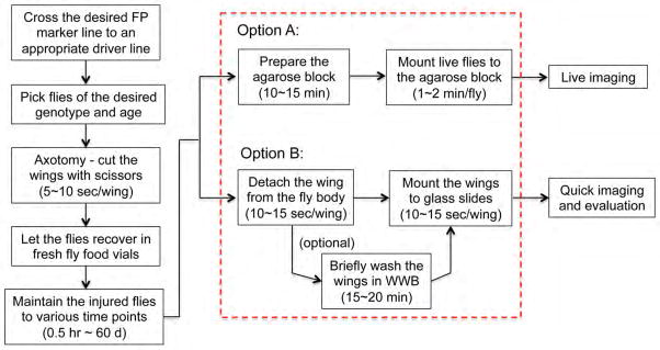
A flowchart of the major steps in the procedure of acute axotomy and in vivo imaging of the wing nerve. The approximate time needed for each of the key steps is noted. After some practice, the key preparation steps for preparation of one slide for in vivo imaging highlighted in the dashed box can be completed within 30 min. FP, fluorescent protein; WWB, wing washing buffer, see REAGENT SETUP for details.
Dual fluorescent labeling of the wing nerve
In order to label the neuronal and the glial components of the wing nerve separately in vivo, we employ two expression systems: the GAL4/UAS25 and the LexA/LexAop26, 27 expression systems. In general, we use a neuronal promoter-GAL4 line (e.g., appl-GAL4) to drive a fluorescent protein (FP) marker that is under the control of UAS (e.g., UAS-mCD8-ChRFP), at the same time as using a glial promotor-LexA::GAD line (e.g., repo-LexAop::GAD) to drive the expression of another FP marker that is under the control of LexAop (e.g., LexAop-rCD2-GFP). In this case, the neurons and axons are labeled in red (appl-GAL4>UAS-mCD8-ChRFP) while the glial cells are labeled in green (repo-LexAop::GAD>LexAop-rCD2-GFP) in the same animal (Fig. 1).
The color and the subcellular localization of the FP markers can be selected according to the need of each experiment and the preference of the individual researcher. The transgenic fly lines that are frequently used in our studies to label the neuronal and glial components include:
GAL4 driver lines:
appl-GAL4: expresses GAL4 in neurons.
repo-GAL4: expresses GAL4 in glia.
dpr-GAL4: expresses GAL4 in the chemosensory neurons of the wing margin bristles; also expresses in the leg.
UAS FP lines:
UAS-mCD8-GFP: expresses membrane-bound GFP.
UAS-mCD8-ChRFP: expresses membrane-bound Cherry RFP.
UAS-RedStinger: expresses a variant DsRed protein with a nuclear localization signal.
UAS-mitoGFP: expresses GFP with a mitochondrial import signal.
LexA::GAD driver lines:
nSyb-LexA::GAD: expresses LexA::GAD in neurons.
repo-LexA::GAD: expresses LexA::GAD in glia.
LexAop FP lines:
LexAop-rCD2-GFP: expresses membrane-bound GFP.
LexAop-mCherry.myr: expresses membrane-bound mCherry RFP.
We note that the range of expression systems continues to multiply27,28, expanding the diversity of cell types that can be labeled and expression approaches available for use in pathway manipulation and screens.
MATERIALS
REAGENTS
Transgenic fly strains carrying the desired FP marker or promoter
Standard fly food (use vials for flies after injury or while aging)
SeaPlaque™ low melting agarose (Lonza, cat. # 50100)
Distilled water
Vectashield mounting medium for fluorescence (Vector Labs, cat. # H-1000)
Nail polish (Electron Microscopy Sciences, cat. # 72180)
Type F immersion liquid (Leica, cat. # 11 513 859) !CAUTION Avoid contact and inhalation. May cause eye and skin irritation.
PBS powder (Sigma-Aldrich, cat. # P3813-10PAK)
Triton X-100 (Sigma-Aldrich, cat. # T9284-500ML)
20% (wt/vol) Paraformaldehyde (Electron Microscopy Sciences, cat. # 15713) !CAUTION Formaldehyde (paraformaldehyde) is considered a carcinogen and highly toxic. Cause strong irritation to skin, eye and respiratory tract when contacted or inhaled. ▲CRITICAL Do not freeze. Store at room temperature (20 °C). Once the ampoule is open, use immediately to make Wing Wash Buffer (see Reagent Setup below).
REAGENT SETUP
10 × PBS: Add 100 mL distilled water to 1 pack of PBS powder. Shake well to dissolve the PBS powder. The solution is stable for many months at room temperature.
Triton X-100, 20% (vol/vol): Triton X-100 is diluted in distilled water. ▲CRITICAL Shake well and prepare in advance. The viscosity of the detergent requires time to fully mix. Can be stored at room temperature for up to 1 month.
Wing Wash Buffer (WWB): Make 4% (wt/vol) formaldehyde in 1 × PBS with 0.2% (vol/vol) Triton X-100 from the above stock solutions with distilled water. ▲CRITICAL Prepare freshly for each experiment. Aliquots frozen at −20 °C can be used up to 1 month but with reduced fixation efficacy.
3% (wt/vol) agarose gel: Add 3 g agarose and 100 mL distilled water to a large bottle or flask, mix well, microwave for 1 min × 3 times. Swirl the flask in between each heating to make sure agarose is completely melted and dissolved, but avoid getting air bubbles in. !CAUTION Use low power of the microwave and short duration each time to avoid over-heating. Also, leave the cap loose if using a bottle. ▲CRITICAL Let the mixture cool and settle in a water bath set to 55 °C. This will also allow the air bubbles to release. The unused agarose solution can be stored in 4 °C for a few months.
EQUIPMENT
Microscopy and photography equipment
Upright fluorescence microscope (Leica, DM6000 B)
High speed camera system (Leica, DFC360 FX)
Mercury lamp (Leica, Kubler CODIX)
The software for obtaining microscopic imaging and analyzing data (Leica, LAS AF software)
Confocal microscope (Leica, TSC SP5)
Motorized stage
Air table for vibration control
-
Objective Lenses:
HC PL FLUOTAR 10.0×0.30: a dry lens for finding the sample of interest.
HCX PL APO CS 20.0×0.70: a dry lens for scoring and quick imaging.
HCX APO L U-V-I 40.0×0.80: a water lens for living imaging.
HCX PL APO CS 63.0×1.40: an oil lens for high-resolution imaging.
The filter setups for visualization of GFP and mCherry fluorescence are given in Fig. 3.
Figure 3. The filter settings for visualization of GFP and mCherry fluorescence of the wing nerve.
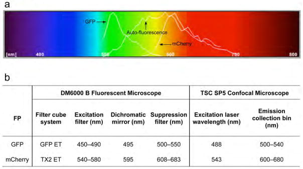
(a) The emission spectrum of GFP and mCherry are presented together with the auto-fluorescence of the wing. Note that the y-axis indicates the relative emission power of a fluorochrome at indicated wavelengths, which is relative to the maximum emission of the fluorochrome within the excitation spectrum tested, not an absolute value. Thus, although the wing has a wide spectrum of autofluorescence, its intensity is usually lower than the intended GFP or mCherry markers. With the recommended filter settings listed in (b), one can obtain an image of the highlighted wing nerve without excessive background auto-fluorescence using either a fluorescent light microscope (e.g., Leica DM6000 B) or a confocal microscope (e.g., Leica TSC SP5).
Other equipment
Dissecting microscope (Leica SZ60)
Spring scissors (Fine Science Tools, cat. # 15000-08)
Dumont #5 forceps (Fine Science Tools, cat. # 11252-23)
Fine hair paintbrush (Utrecht 228)
Colorfrost/Plus microscope slides (Fisher, cat. # 12-550-19)
Coverslips, 22 × 40 mm, no. 1 (Gold Seal, cat. # 3316)
Nunc Lab-Tek chamber slide, one-well (Fisher, cat. # 12-565-15)
Nutator (Fisher, cat. # 260100F)
Water bath (Precision 280)
Microwave oven
Eppendorf tubes
Pipettes and tips
Kimwipes
Humid chamber: Place a few wet Kimwipes at the bottom of a large Petri dish (150 mm × 15 mm). Press down the Kimwipes firmly to make the surface flat. Put the dish cover on once the mounted agarose blocks are placed in it, and then keep it at 4 °C before imaging.
Agarose block chamber: The agarose block chambers are made from Nunc Lab-Tek chamber slides (one-well). The chamber wall is cut by a machine shop to reduce the height of the wall to ~ 5 mm, such that the slide can move easily beneath the objectives of a microscope.
PROCEDURE
Precise axotomy by a simple wing cut. ❖Timing 10~15 min
-
1
Pick the adult flies of the desired genotype and age (we usually cut the wings of flies at the age of 3d~5d).
-
2
Anesthetize the flies on a CO2 pad and examine the flies under the dissecting light microscope (Fig. 4a).
-
3
Exclude any fly whose wing shows visible damage (nicks or tears).
-
4
Use a fine hair paintbrush to position the flies ventral side down.
▲CRITICAL STEP Avoid poking the fly with the tips of the forceps. It can easily injure the animal.
-
5
Use the handheld spring scissors to cut off the wing at the junction site of the L1 vein and the costal vein (Fig. 4b).
▲CRITICAL STEP Turn the CO2 pressure low such that it is just high enough to keep the flies anesthetized. Excessive CO2 will cause the flies to fold their wings medially and make the cutting difficult.
-
6
Make sure the costal vein, which will be used as an internal control, is not injured after the cut; otherwise, exclude the fly.
-
7
Cut only one wing and leave the other wing of the same fly uncut. (If right-handed, it is usually easier to cut the right wing and leave the left wing uncut.) The uncut wing will be used as an internal self-control to compare with the injury-induced responses of the cut wing.
Figure 4. The wing cut preparation.
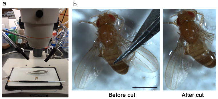
(a) A picture of the acute axotomy tools, showing a dissecting microscope, a CO2 pad, a fine-haired paintbrush, spring scissors, and anesthetized flies. (b) Pictures showing the fly wing before and after cut, with the scissors cutting over the junction site of the costal vein and the L1 vein. This is where the last cluster of L1 neurons is situated (see Fig. 7). Thus, a cut at this site transacts all of the axons of the L1 margin nerve, but leaves the costal vein nerve intact; the costal nerves can be used as an internal control in experiments. (Fig. 4b is reprinted from 13.) Scale bar: 1 mm.
Recovery and maintenance of the flies after injury. ❖Timing Depending on the desired time points for imaging, this can vary from 0.5 h to up to 60d
-
8
Release injured flies from the CO2 pad by gently brushing them into a standard fly food vial.
▲CRITICAL STEP Use clean, fresh fly food that is pre-warmed to room temperature. Place no more than 10 flies per vial.
-
9
Label the vial with the fly genotype, the injury date, and the planned date for imaging.
-
10
Place the vial in a 25 °C incubator and let the flies recover.
-
11
Transfer the flies to fresh food vials every 2~3d.
▲CRITICAL STEP To transfer the flies, gently knock the bottom of the vial on a thick computer mouse pad and quickly flip the vial to transfer the flies into the new vial. Avoid shaking the vial vigorously or knocking the vial on a hard surface, which can cause unintended damage to the wing.
Preparation for in vivo imaging
-
12
Once the flies are aged to the appropriated time points, retrieve them from the incubator and examine the flies under the dissecting microscope.
▲CRITICAL STEP Exclude the flies whose wing show visible damage other than just the wing cut. In addition, pigment deposition along the wing veins is another indication that the wing may have been damaged, for example, bent or crushed, even though a tear or a hole is not seen on the wing. Exclude those flies as well.
? TROUBLESHOOTING
-
13
Prepare the wings for imaging using one of the two methods described below: option A for live imaging of the wing nerve, and option B for quick imaging of detached wings and scoring degeneration severity:
Option (A): for live imaging of the wing nerve. ❖Timing 25~30 min per block
Re-heat the 3% agarose mixture.
Let it cool in a water bath set to 55°C.
-
While the mixture is acclimating to temperature, knock the flies out on a CO2 pad.
▲CRITICAL STEP Make sure the flies are completely asleep before starting to mount them onto the agarose. Otherwise, the flies will wiggle as they wake up and cause air bubbles between the wings and the gel, making the wing difficult to image.
Use the brush to position the flies ventral side up, with the wings flat and extending out from the body.
-
Pour agarose into an agarose block chamber and fill it up.
▲CRITICAL STEP Do not over-fill the chamber, or it will form a convex surface once the gel is hardened. The convex surface is difficult to work with when using the 40× water lens to image.
Use a pair of blunt ended forceps to pick up the fly by holding the legs. Be gentle and do not nip the legs.
Transfer the fly from the CO2 pad to the agarose block (Fig. 5a).
Gently place the wings flat on the agarose. Lightly press the belly and the head of the fly against the agarose to help the fly stick to the gel. Make sure the wings are angled out from the fly body to allow the microscope objective access the wing nerve bundle along the wing margin and the wing root area (Fig. 5b).
-
Line up about 5 flies per block, then place the block into the humid chamber and move it to 4°C (Fig. 5c). This allows the agarose to cool and harden, and helps keep the flies immobile after they are removed from the CO2 pad.
▲CRITICAL STEP Pour the agarose blocks one by one right before mounting flies. Once poured, mount the flies quickly before the agarose cools. Do not attempt to pour multiple agarose blocks at a time or to mount too many flies onto one block. If the agarose cools before flies are mounted, the flies will not stick firmly to the gel.
✓ PAUSE POINT While mounting more flies to make a batch of blocks, the already mounted blocks can be left in a humid chamber at 4 °C for up to 3 h before imaging.
? TROUBLESHOOTING
Figure 5. The preparation for live imaging of the wing nerve.

(a) Live flies mounted on the agarose block. (b) A closer look of the live fly mounted on the agarose block. Note that the flies are mounted on their backs (dorsal side), with the wings flat and angled out from the fly body. This wing posture gives sufficient space to allow the microscope objective to access the wing margin and the wing root area in order to image the wing nerve bundle. (c) The mounted agarose block is kept in a humid chamber at 4°C before imaging. Scale bar: 1 mm.
Option (B): for scoring and quick imaging of detached wings. ❖TIMING 20~30 sec per fly
Gather two pairs of fine tip forceps, a fine hair paintbrush, and a microscope slide.
Make a wet pad by dampening a few Kimwipes (for wiping the tips of the forceps during dissection) (Fig. 6a).
Make stripes of Vectashield mounting medium (lines of 2 mm × 12 mm, at intervals of 2~3 mm apart) on the slide (Fig. 6a). Each stripe is good for mounting a vial of flies (up to 10 flies) and each slide can hold 5~8 mounting stripes. Thus, each slide can be mounted with 100~160 wings. This is especially convenient when doing screens, whereby a large number of wings can be rapidly scored with ease.
Knock out the flies on a CO2 pad (Fig. 6a).
Use the fine paintbrush to orientate the fly ventral side down or on its side.
Remove the wing from the fly body using the tips of the fine forceps. Hold and snap off the wing at the wing hinge (Fig. 6b). Avoid touching the wing blade with the forceps.
-
Place the wing on the mounting stripe with the ventral side up. This is to avoid trapping bubbles underneath the wing and to get consistent images across all wings.
▲CRITICAL STEP Pay attention to the orientation of the fly before removing the wing from the body. It is much harder to tell which side is ventral and which side is dorsal once the wing is removed. Note that the detached wing is slightly curved upwards when the ventral side is up (Fig. 6b).
Repeat Steps v to vii to remove and mount the other wing of the fly.
Place the two wings in a pair side-by-side, aligning the anterior wing margin of the two wings from the same fly parallel to each other, allowing visualization in the same image with a single capture (Fig. 6d).
Mount the rest of the flies from the same vial in one mounting stripe.
Continue to mount the other vials of flies in the rest of the mounting stripes.
-
Put the coverslip on and lightly press it with the other end of the fine paintbrush to remove air bubbles.
▲CRITICAL STEP Do not press the coverslip too hard and avoid pressing directly on top of any wing. The air bubbles are due to the hydrophobicity of the cuticle covering the fly wing. For scoring and quick imaging, it is fine to leave bubbles in the slide as long as they do not obscure the L1 vein or the wing root nerve bundle.
(Optional) To get rid of the bubbles for better images, wash the detached wings in an Eppendorf tube with WWB on a nutator at room temperature for 15~20 minutes. The detergent in WWB reduces the surface tension, allowing it to wet the wing more effectively. Briefly rinse the wings in 1 × PBS and mount them on a microscope slide as described in Steps vii to x.
-
Seal the sides of the coverslip with nail polish.
♪ PAUSE POINT The mounted wing slides (WWB washed or not) can be stored at 4 °C for several hours before imaging.
▲CRITICAL STEP Note that although the WWB contains 4% formaldehyde, it does not seem to penetrate the cuticle, but rather gets into the veins from the open end of the detached wing. Fixation may not be thorough and thus it is recommended to score or image the mounted wings as soon as possible. We usually score and image the detached wings within 4 h after they are removed from the fly body.
? TROUBLESHOOTING
Figure 6. The preparation for quick imaging and scoring of the nerve.

(a) The instruments required for detaching and mounting fly wings to slides include two pairs of fine forceps, a wet pad (for wiping the tips of the forceps), a CO2 pad, a brush, a glass slide with Vectashield mounting medium positioned in stripes. (b) The wings are removed using the forceps where indicated (red box). Avoid touching the wings with the forceps. The wings should be mounted flat on the slide with the ventral side up. (Insert: note the wing is slightly curved upwards when the ventral side is up. This curvature can help distinguish the ventral side from the dorsal side once the wing is detached from the fly body.) (c) A picture showing the uncut and cut wings detached from the same fly mounted side-by-side on the slide. The pair of the wings highlighted in the red box is imaged in (d). Note that the cut wing nerve (right) shows striking axon fragmentation, whereas the uncut wing nerve (left) retains a smooth appearance (see white boxes of higher magnification inserts). The nerve axons are highlighted with mCherry and the dpr-GAL4 driver. Scale bar: 1 mm (c) and 50 μm (d).
In vivo imaging. ❖TIMING 3 h
-
14
Transfer the mounted agarose blocks or the slides to the confocal microscope or the fluorescent microscope.
▲CRITICAL STEP Carry the agarose blocks in the humid chamber and keep them on ice during transportation.
-
15
Turn on the power of the microscope, the computer, the mercury lamp, the laser and the scanner of the confocal.
-
16
Open the LAS AF software, activate the control components and adjust the imaging system including the microscope, the lasers, the confocal scanner unit or the CCD camera for the fluorescent microscope, and the filter settings (see Fig. 3).
-
17
Load an agarose block or a slide with mounted wings on the microscope stage holder.
-
18
Switch on the fluorescence light and use the 10× dry lens to check the block/slide.
-
19
Select a wing that is mounted flat and the wing nerve along the wing margin and in the wing root that is accessible.
▲CRITICAL STEP For live imaging of the wings mounted on the agarose block, use only the 40× water lens. For scoring and quick imaging of the wings mounted on a slide, all the objective lenses (20× dry, 40× water, and 63× oil) can be used. The imaging procedure is similar. Below, we use the 40× water lens as an example to demonstrate the live imaging procedure.
-
20
Lower the stage and put a drop of water on the center of the region of interest.
-
21
Switch to the 40× water lens; immerse the lens into the water droplet.
-
22
Turn on the “live” mode of the LAS AF software, check the intensity of each labeled FP marker, adjust the settings for power strength, gain, offset, exposure time, etc. for each channel.
-
23
Set the acquisition parameters such as repeat number for scanning, z-stack step depth, sequential imaging settings, time interval between each data collection cycles, duration for the time-lapse recording, etc.
▲CRITICAL STEP Use lower laser power (< 30% of the argon laser), lower scan number for acquisition, and a longer interval for time-lapse to reduce photobleach and phototoxicity.
▲CRITICAL STEP As the agarose gel evaporates, the focal plate of the wing drifts. It is important to manually check the focus (e.g. every 15 min) and make sure there is enough water immersing the lens.
-
24
Repeat Steps 19–23 to continue to image the other wings on the block or to switch to another block. We usually do not continuously image a single block for more than 3 h.
▲CRITICAL STEP As the flies are immobilized on their backs, their legs can move freely once they wake up. Also, the flies will try to get off from the gel by twisting the body. This may make focusing difficult. Thus, it is important to keep the blocks that are not being actively imaged on ice.
? TROUBLESHOOTING
-
25
After imaging, release the flies from the block by pipetting water onto the agarose and gently brushing the fly legs to loosen the fly from the gel.
-
26
Brush the flies into a clean, fresh, pre-warmed fly food vial. Let them recover and maintain them as described in Steps 8–11 to the next time point for imaging.
▲CRITICAL STEP Avoid frequent mounting and de-mounting of the flies to/from the agarose block, as this causes increased lethality and additional damage to the wing. For experiments involving multiple time points over an extended aging duration (e.g., 1d, 5d, 10d, 15d, 30d through 60d), it is always better to prepare groups of flies for each time point than to repeatedly mount/de-mount and image the same group of flies.
❖TIMING
Steps 1–7, acute axotomy by a simple wing cut: 10~15 min
Steps 8–11, recovery and maintenance of the injured flies: time varies depending on the desired time points for imaging, ranging from 0.5 h to 60d.
Step 12, examination of the injured wings before mounting: 5 min
Step 13A, preparation for live imaging: 25~30 min per block
Step 13B, preparation for scoring and quick imaging: 20~30 sec per fly
Steps 14–26, live imaging: setup and adjusting the microscope and the imaging systems takes ~ 30 min. The time-lapse images can be obtained as long as the fly is alive. We usually do not image a single wing or a single block continuously for more than 3 h.
? TROUBLESHOOTING
Troubleshooting advice can be found in Table 1.
Table 1.
Troubleshooting table.
| Step | Problem | Possible reason | Possible solution |
|---|---|---|---|
| 12 | The wing shows damage other than the wing cut | Improper handling of the flies | Avoid touching the wings with scissors or forceps. Be gentle when transferring flies to new food vials during aging. |
| 13A | Bubbles in the agarose | Air bubbles are created during heating | Swirl the bottle after heating the agarose in the microwave oven. Heat it again, swirl, and let it cool down and settle to release the bubbles. |
| Flies wake up when they are being mounted to the agarose block or while the agarose is hardening | Flies are not sufficiently immobilized | Leave the flies on the CO2 pad longer. Make sure they are completely asleep before mounting. | |
| Flies get off the agarose block once no longer anesthetized with CO2 | Flies do not stick to the gel firmly | Mount the flies quickly once the agarose is poured into the block. Lightly press the fly belly and the fly head to help the animal adhere to the agarose firmly. Keep the block at 4°C while the gel is hardening. | |
| Flies died during mounting | The agarose is too hot | Allow the melted agarose to cool down in the 55°C water bath. Measure the temperature of the agarose with a thermometer to make sure the agarose is indeed cooled down to the desired temperature before pouring it into the block chamber. | |
| 13B | Wings overlap on the slide | Wings are mounted too close to each other | Leave enough of a gap between each pair of wings and between each mounting stripe. Use as little medium as possible to avoid the wings floating around once the coverslip is positioned. |
| 24 | Difficult to keep the image in focus during time-lapse recording | The agarose block dries out, or the flies wake up and twist their body | Keep the mounted agarose block in a humid chamber on ice before imaging. Do not image a single fly or a single block too long (< 3hr is recommended). Alternate between blocks to keep the gel wet and the flies still. |
| Reduction of fluorescence intensity over time | Photobleach | Use lower laser power, scanning frequency, and imaging duration | |
| Flies died during imaging | Phototoxicity | Use lower laser power, scanning frequency, and imaging duration | |
| Block is dried out | Keep the blocks that are not being imaged in the humid chamber. Topping the agarose block with a thin layer of water helps preventing them from drying out. | ||
| Flies are injured | Be careful not to injure the flies when switching lenses or when lowering the water lens into the droplet. |
ANTICIPATED RESULTS
By using this acute axotomy and in vivo imaging protocol, we can visualize and characterize injury-induced responses directly on the wing nerve. For example, as show in Fig. 7, transection of the L1 nerve by the wing cut induces dramatic axonal fragmentation and degeneration (note the loss of axonal GFP in Fig. 7a) and significant glial proliferation (see the increase of glial mCherry Fig. 7b). These responses are specific and autonomous to the injury, as the uninjured costal nerve, despite being adjacent to the L1 nerve, does not show an axonal or glial response (Fig. 7c).
Figure 7. Representative images of neural injury-induced axonal and glial responses.
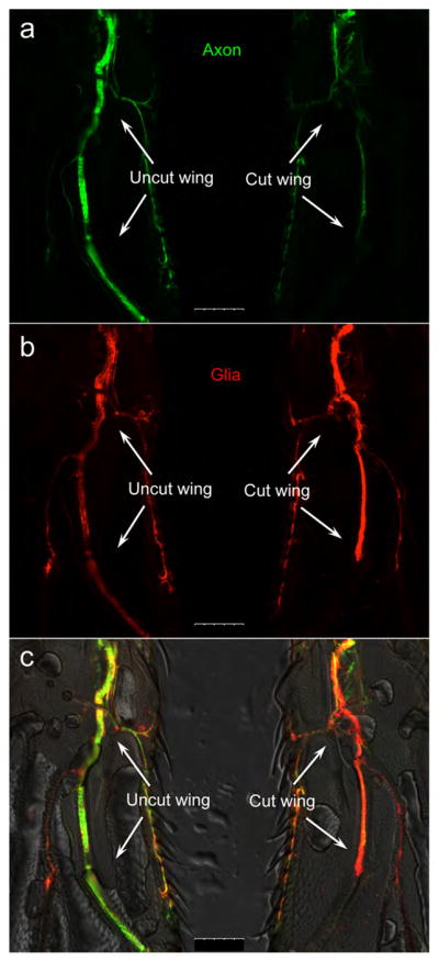
Representative images of a pair of the uncut wing (left) and the cut wing (right) from the same fly mounted side-by-side on a glass slide. (a) The axons (green) are highlighted by nsyb-LexA::GAD>LexAop-rCD2-GFP and (b) the glia (red) are highlighted by repo-GAL4>UAS-mCD8-ChRFP, and (c) they are merged on a DIC image of the wings. At D7 after injury, axotomy of the L1 nerve causes dramatic loss of the axonal GFP signal, indicative of injury-induced axon degeneration (a); there is also a significant increase in the glial mCherry intensity, suggesting injury-induced glial proliferation (b). Note that in both the cut and the uncut wings, the costal nerve is not injured and its GFP and mCherry fluorescence remain largely unchanged, which suggests that the injury-induced axonal and glial responses are autonomous and specific to the nerve bundle that has been damaged. Scale bar: 75 μm.
In combination with the powerful genetic tools of Drosophila, we anticipate that studies using the fly wing paradigm and in vivo imaging will not only uncover evolutionarily conserved core mechanisms that underlie axonal injury, but also provide the foundation to identify novel therapeutic targets for promoting neuroprotection and neural regeneration. In theory, this type of approach is applicable to other nerve systems in the fly, to dissect the detailed molecular mechanisms that impact this crucial biological process with the power of Drosophila tools.
Acknowledgments
We are grateful to M. Landgraf, B. White, T. Lee, and the Bloomington Drosophila Stock Center at Indiana University for providing transgenic flies used in this work, as well as G. Rubin, B. Pfeiffer, N. Aijoscha for sharing unpublished reagents. We also thank X. Teng and M. Geary for their excellent technical assistance, M. Parisi for the nsyb-LexA::GAD>LexAop-rCD2-GFP recombinant fly line, and L-Y. Hao, S-Y. Shieh and the other members of the Bonini lab for their thoughtful discussions. NMB is an investigator of the Howard Hughes Medical Institute. This work was supported by an NIH EUREKA award (grant 1R01NS066312) and an Ellison Medical Foundation Senior Scholar in Aging Award to N.M.B.
Footnotes
AUTHOR CONTRIBUTIONS
Y.F., L.S., and N.M.B. conceived the project and developed the protocol; Y.F. designed and performed the experiments and analyzed the results; Y.F. and N.M.B. wrote the paper.
COMPETING FINANCIAL INTERESTS
The authors declare no competing financial interests.
References
- 1.Wilson JR, Cadotte DW, Fehlings MG. Clinical predictors of neurological outcome, functional status, and survival after traumatic spinal cord injury: a systematic review. J Neurosurg Spine. 2012;17:11–26. doi: 10.3171/2012.4.AOSPINE1245. [DOI] [PubMed] [Google Scholar]
- 2.Rosenfeld JV, et al. Early management of severe traumatic brain injury. The Lancet. 2012;380:1088–1098. doi: 10.1016/S0140-6736(12)60864-2. [DOI] [PubMed] [Google Scholar]
- 3.Tuszynski MH, Steward O. Concepts and methods for the study of axonal regeneration in the CNS. Neuron. 2012;74:777–791. doi: 10.1016/j.neuron.2012.05.006. [DOI] [PMC free article] [PubMed] [Google Scholar]
- 4.Becker CG, Becker T. Adult zebrafish as a model for successful central nervous system regeneration. Restor Neurol Neurosci. 2008;26:71–80. [PubMed] [Google Scholar]
- 5.Chen L, Chisholm AD. Axon regeneration mechanisms: insights from C. elegans. Trends Cell Biol. 2011;21:577–584. doi: 10.1016/j.tcb.2011.08.003. [DOI] [PMC free article] [PubMed] [Google Scholar]
- 6.Fang Y, Bonini NM. Axon Degeneration and Regeneration: Insights from Drosophila Models of Nerve Injury. Annu Rev Cell Dev Biol. 2012;28:575–597. doi: 10.1146/annurev-cellbio-101011-155836. [DOI] [PubMed] [Google Scholar]
- 7.Toomre D, Bewersdorf J. A New Wave of Cellular Imaging. Annu Rev Cell Dev Biol. 2010;26:285–314. doi: 10.1146/annurev-cellbio-100109-104048. [DOI] [PubMed] [Google Scholar]
- 8.Taylor AM, et al. A microfluidic culture platform for CNS axonal injury, regeneration and transport. Nat Methods. 2005;2:599–605. doi: 10.1038/nmeth777. [DOI] [PMC free article] [PubMed] [Google Scholar]
- 9.Cho S, Wood A, Bowlby MR. Brain slices as models for neurodegenerative disease and screening platforms to identify novel therapeutics. Curr Neuropharmacol. 2007;5:19–33. doi: 10.2174/157015907780077105. [DOI] [PMC free article] [PubMed] [Google Scholar]
- 10.Hutter H. Five-colour in vivo imaging of neurons in Caenorhabditis elegans. J Microsc. 2004;215:213–218. doi: 10.1111/j.0022-2720.2004.01367.x. [DOI] [PubMed] [Google Scholar]
- 11.Ghosh-Roy A, Chisholm AD. Caenorhabditis elegans: a new model organism for studies of axon regeneration. Dev Dyn. 2010;239:1460–1464. doi: 10.1002/dvdy.22253. [DOI] [PMC free article] [PubMed] [Google Scholar]
- 12.Bejjani RE, Hammarlund M. Neural Regeneration in Caenorhabditis elegans. Annu Rev Genet. 2012;46:499–513. doi: 10.1146/annurev-genet-110711-155550. [DOI] [PMC free article] [PubMed] [Google Scholar]
- 13.Fang Y, Soares L, Teng X, Geary M, Bonini NM. A Novel Drosophila Model of Nerve Injury Reveals an Essential Role of Nmnat in Maintaining Axonal Integrity. Curr Biol. 2012;22:590–595. doi: 10.1016/j.cub.2012.01.065. [DOI] [PMC free article] [PubMed] [Google Scholar]
- 14.Lessing D, Bonini NM. Maintaining the brain: insight into human neurodegeneration from Drosophila melanogaster mutants. Nat Rev Genet. 2009;10:359–370. doi: 10.1038/nrg2563. [DOI] [PMC free article] [PubMed] [Google Scholar]
- 15.Potter CJ, Turenchalk GS, Xu T. Drosophila in cancer research. An expanding role. Trends Genet. 2000;16:33–39. doi: 10.1016/s0168-9525(99)01878-8. [DOI] [PubMed] [Google Scholar]
- 16.Keene AC, Waddell S. Drosophila olfactory memory: single genes to complex neural circuits. Nat Rev Neurosci. 2007;8:341–354. doi: 10.1038/nrn2098. [DOI] [PubMed] [Google Scholar]
- 17.Sehgal A, et al. Molecular analysis of sleep: wake cycles in Drosophila. Cold Spring Harb Symp Quant Biol. 2007;72:557–564. doi: 10.1101/sqb.2007.72.018. [DOI] [PubMed] [Google Scholar]
- 18.Leyssen M, et al. Amyloid precursor protein promotes post-developmental neurite arborization in the Drosophila brain. EMBO J. 2005;24:2944–2955. doi: 10.1038/sj.emboj.7600757. [DOI] [PMC free article] [PubMed] [Google Scholar]
- 19.MacDonald JM, et al. The Drosophila cell corpse engulfment receptor Draper mediates glial learance of severed axons. Neuron. 2006;50:869–881. doi: 10.1016/j.neuron.2006.04.028. [DOI] [PubMed] [Google Scholar]
- 20.Hoopfer ED, et al. Wlds protection distinguishes axon degeneration following injury from naturally occurring developmental pruning. Neuron. 2006;50:883–895. doi: 10.1016/j.neuron.2006.05.013. [DOI] [PubMed] [Google Scholar]
- 21.Ayaz D, et al. Axonal injury and regeneration in the adult brain of Drosophila. J Neurosci. 2008;28:6010–6021. doi: 10.1523/JNEUROSCI.0101-08.2008. [DOI] [PMC free article] [PubMed] [Google Scholar]
- 22.Xiong X, et al. Protein turnover of the Wallenda/DLK kinase regulates a retrograde response to axonal injury. J Cell Biol. 2010;191:211–223. doi: 10.1083/jcb.201006039. [DOI] [PMC free article] [PubMed] [Google Scholar]
- 23.Stone MC, Nguyen MM, Tao J, Allender DL, Rolls MM. Global up-regulation of microtubule dynamics and polarity reversal during regeneration of an axon from a dendrite. Mol Biol Cell. 2010;21:767–777. doi: 10.1091/mbc.E09-11-0967. [DOI] [PMC free article] [PubMed] [Google Scholar]
- 24.Garcia-Alonso LA. Postembryonic sensory axon guidance in Drosophila. Mol Life Sci. 1999;55:1386–1398. doi: 10.1007/s000180050379. [DOI] [PMC free article] [PubMed] [Google Scholar]
- 25.Brand AH, Perrimon N. Targeted gene expression as a means of altering cell fates and generating dominant phenotypes. Development. 1993;118:401–415. doi: 10.1242/dev.118.2.401. [DOI] [PubMed] [Google Scholar]
- 26.Lai SL, Lee T. Genetic mosaic with dual binary transcriptional systems in Drosophila. Nat Neurosci. 2006;9:703–709. doi: 10.1038/nn1681. [DOI] [PubMed] [Google Scholar]
- 27.Pfeiffer BD, Ngo TT, Hibbard KL, Murphy C, Jenett A, Truman JW, Rubin GM. Refinement of tools for targeted gene expression in Drosophila. Genetics. 2010;186:735–755. doi: 10.1534/genetics.110.119917. [DOI] [PMC free article] [PubMed] [Google Scholar]
- 28.Potter CJ, Tasic B, Russler EV, Liang L, Luo L. The Q system: A repressible binary system for transgene expression, lineage tracing, and mosaic analysis. Cell. 2010;141:536–548. doi: 10.1016/j.cell.2010.02.025. [DOI] [PMC free article] [PubMed] [Google Scholar]
- 29.Wang JW, Beck ES, McCabe BD. A modular toolset for recombination transgenesis and neurogenic analysis of Drosophila. PLoS One. 2012;7:e42102. doi: 10.1371/journal.pone.0042102. [DOI] [PMC free article] [PubMed] [Google Scholar]