Abstract
The short working distance of microscope objectives has severely restricted the application of optical micromanipulation techniques at larger depths. We show the first use of fiber-optic tweezers toward controlled guidance of neuronal growth cones and stretching of neurons. Further, by mode locking, the fiber-optic tweezers beam was converted to fiber-optic scissors, enabling dissection of neuronal processes and thus allowing study of the subsequent response of neurons to localized injury. At high average powers, lysis of a three-dimensionally trapped cell was accomplished.
Keywords: optical tweezers, laser microbeam, optical stretcher, optical micromanipulation, optical fiber, neuron growth, cellular lysis
1 Introduction
Optical scissors and tweezers have been tools of the biologist for over two decades.1,2 Recently, the application of optically based micromanipulation has led to an explosion of new applications. In particular, optical tweezers and scissors have had a major impact on the fields of biophysics3,4 and colloidal science,5 with applications ranging from measurement of force at the single molecule level6–9 to disease diagnosis10 to therapeutic applications11 in the field of assisted reproductive therapy (ART). Recently, while optical tweezers have been shown to enhance and guide neuronal growth,12,13 femtosecond laser scissors have been employed for axotomy of neurons, allowing measurement of the regeneration process.14 In contrast to the short working distance of the high numerical aperture (NA) microscope objectives, optical tweezers and scissors based on a single optical fiber will enable micromanipulation at much larger depths and thus open up additional avenues for biophysics and nanoscience research. While no report exists on single-fiber scissors, earlier attempts to trap in three dimensions using a single optical fiber have not been successful, even with a hemispherical lens built on the tip of fiber.15,16 This failure is presumably due to the dominance of the scattering force in the axial direction. While particle trap-ping using a single fiber probe with an annular light distribution17 required balance of opposing optical and electrostatic forces, recently, pure-optical 3-D trapping was demonstrated using a tapered18 and axicon-tip fiber.19
In this report, we show that by microshaping of the axicon fiber tip, effective three-dimensional (3-D) trapping and micro-dissection is possible. We demonstrate the use of the fiber-optic tweezers for neuronal stretching and directed axonal growth guidance and fiber-optic scissors for dissection of neuronal growth cones and rapid cellular lysis.
2 Materials and Methods
2.1 Fabrication of Axicon-Tip Fiber
A single-mode optical fiber appropriate for 800 nm was used for preparing the axicon-tip fiber. One end of the mechanically cleaved bare single-mode fiber was dipped into 48% hydrofluoric (HF) acid containing a protective layer (e.g., Toluene) at the top. As described by Hoffmann et al.,20 the cone angle of the fiber tip is determined by the contact angle of HF with the fiber. The etching process is self-terminating, and the cone angle is influenced by the liquid used as a protection layer. The small cone angle fiber tip has been used earlier for in-depth trapping of low-index microscopic objects.21 For varying the tip cone angle over a wider range (e.g., for 60 deg and 90 deg) and for mechanical rigidity, a two-step etching technique22 was employed. After the first selective chemical etching step, the tapered region has a cone angle of 30 deg, and the diameter at the end of the fiber is found to be about 40 μm. The etching time was 100 min. The second step with a selective etching solution22 having higher volume ratio of NH4F results in a sharp apex with a cone angle of ∼90 deg with an etching time of about 140 min. The shape of the tip was optimized considering different experimental conditions. For example, while using it (in an almost horizontal plane) for neuronal growth enhancement, by lengthening the fiber tip region, contact between the cladding of the fiber and the substrate on which cells were grown could be avoided. Figure 1(a) shows a typical axicon-tip fiber. Scanning electron microscopy (SEM) imaging of the fiber tip showed reproducible high-quality fiber tips (data not shown).
Fig. 1.
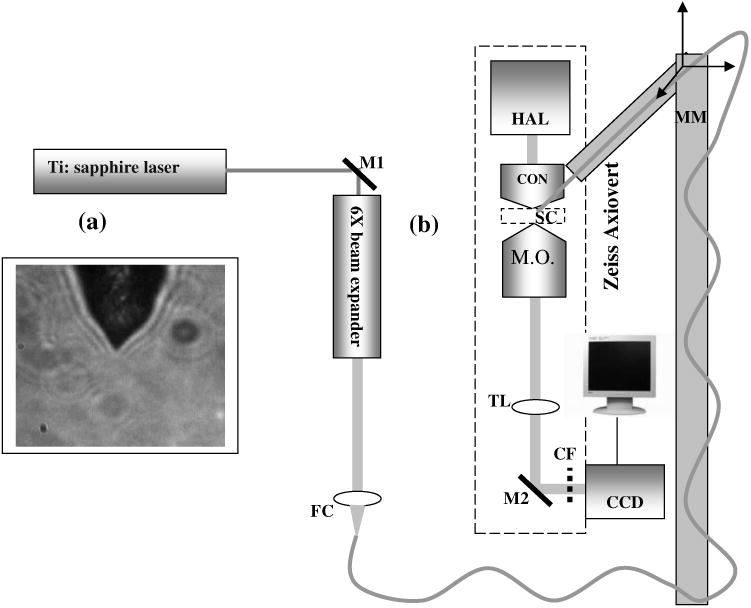
(a) Microscopic image of the tapered tip with 60-deg cone angle. (b) Single-fiber optical tweezers and scissors setup. M1, M2: folding mirrors; M.O.: microscope objective; SC: sample chamber; CON: condenser; HAL: halogen lamp; FC: fiber coupler; MM: motorized manipulator; CF: IR cutoff filter; TL: tube lens.
2.2 Experimental Setup
The experimental setup [Fig. 1(b)] consists of a TEM00 mode output of Ti:Sapphire laser beam (780 nm, Coherent, Inc., Santa Clara, California). The beam is expanded using a 6× beam expander and coupled to the single-mode optical fiber using a 20× objective (FC), and the tip of the fiber was mounted on a mechanical micromanipulator (MM) in order to have 3-D movement controls. In mode locking, the pulse duration is ∼200 fs (frequency 76 MHz) as measured by the manufacturer (using autocorrelation). The spectral width (measured using a spectrometer, Model No. SM24, CVI Spectral Porducts, Putnam, Connecticut) of the mode-locked laser beam coming out of the fiber (length 80 cm) was found to decrease (1.1 nm), implying broadening of the pulse. A 40× microscope objective (M.O.) was used to image the beam profile as well as manipulation events onto the CCD camera using a 200-mm focal length tube lens. The sample chamber was transilluminated using a halogen lamp through a condenser lens. An infrared (IR) cutoff filter (CF) was used to block the laser beam reaching the CCD. Images of the manipulation of objects were digitized using a frame grabber and computer. Moving the objective for a range of 10 μm with a resolution of 2 μm, a series of images of transverse beam profiles were recorded for different tip cone angle fibers.
2.3 Calibration of Trapping Stiffness
To determine the stiffness (Ktrap) of fiber optic tweezers, we used the equipartition theorem method,3 Ktrap=1/2KBT/〈X2〉, where KB is the Boltzmann constant, and T is the temperature of the medium in which the particle is suspended. The chief advantage of this method is that knowledge of the viscous drag coefficient is not required and therefore neither is the particles geometry or fluid viscosity. Polystyrene beads of 2 μm diameter were trapped and used for calibration of the fiber optic tweezers. The positions of the particle in the trap were detected using a centroid detection method.23 A software program on LabView platform was developed for quick analysis of a large number of images. Region of interest (ROI) selection and thresholding was carried out in order to reject background images.
2.4 Cell Culture
NG108 Neuroblastoma and Chinese hamster ovary (CHO) cells were obtained from American Type Culture Collection (Manassas, Virginia). These were grown in Dulbecco's modified Eagle medium (DMEM) and Rosewell Park Institute medium (RPMI) supplemented with 10% fetal bovine serum, respectively (Invitrogen, Calsbad California). Cultures were maintained at 37°C with 5% CO2 supplementation. For cells to be trapped or stretched in the single-fiber optical stretcher, single-cell suspensions (CHO and NG108) were obtained by incubating the cells with 0.25% trypsin-EDTA solution at 37°C for 4 min. After detaching, the activity of trypsin-EDTA was diluted by adding fresh culture medium. This treatment causes the cells to stay suspended as isolated cells for a few hours. The neuronal growth cone guidance experiments were performed at 37°C. Use of external CO2 supplementation was avoided by use of pH-stabilized medium (through addition of 10 mM Hepes) in the neuron growth and dissection experiment.
3 Results and Discussion
3.1 Measurement of Transverse and Axial Trapping Stiffness
Figure 2(a) shows 3-D trapping of a polystyrene particle [refractive index=1.59, diameter 2 μm) using a 90-deg cone angle fiber tip (see also Video 1)]. Translation of the fiber led to transportation of the particle [Fig. 2(b)]. Figure 2(c) shows measured transverse trapping force at different trap beam powers for the 2-μm polystyrene particle. For a fixed beam power, the transverse trapping stiffness was found to be quite high (5.7 pN/μm at beam power of 25 mW) as compared to the axial trapping stiffness (1.4 pN/μm) for the 2-μm polystyrene particle. The slope of the graphs for the transverse and axial directions was found to be 0.056 and 0.22 pN/(μ/mW, respectively.
Fig. 2.
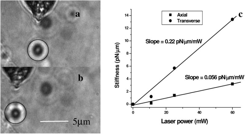
(a) Image of a trapped 2-μm polystyrene particle (circled). (b) Transportation of the trapped particle by maneuvering the fiber tip. (c) Plot of measured stiffness along axial and transverse directions for the 2-μm particle as a function of trap beam power.
Video 1.

Video showing 3-D trapping of a 2-μm polystyrene particle using a 90-deg cone angle fiber tip. Transportation of the particle can be achieved by translation of the fiber. Video corresponds to data in Figs. 2(a) and 2(b). Resolution is 320 × 240 (MPEG, ∼2 MB). [URL: http://dx.doi.org/10.1117/1.2983663.1].
3.2 Trapping and Lysis of Mammalian Cells
In Fig. 3, we show how a single axicon-tip fiber can be deployed to perform optical trapping as well as lysis of biological cells. The cell (CHO), distant from the fiber tip [marked by an arrow in Fig. 3(a)], is attracted toward the fiber tip [Fig. 3(b)] at a power of 95 mW and was stably trapped very close to the axicon tip [Fig. 3(c)]. The trapped cell could be transported to a new location [Figs. 3(d) and 3(e)] by maneuvering the fiber tip. Switching the laser beam on and off alternatively allowed the cell to move close [Fig. 3(g)] or away [Fig. 3(f)] from the fiber tip, ruling out the possibility of nonoptical attraction between the cell and the fiber. By mode locking the near-infrared (NIR) laser beam, femtosecond pulses (∼200 fs, 76 MHz) could be delivered, and the same fiber probe could be used for lysis of the trapped cells [Figs. 3(h) and 3(i)] in a time scale of 600 ± 200 ms. This feature is required24 in many assays to immediately terminate biochemical reactions, thus preventing measurement artifacts resulting from the sample processing. By reducing the average power of the femtosecond fiber-optic microbeam, microinjection25,26 of impermeable exogenous materials into the trapped cells was also possible (data not shown).
Fig. 3.
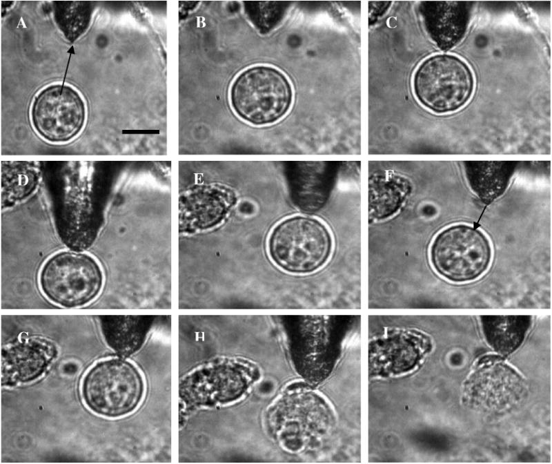
Time-lapse digitized images of trapping, transport, and lysis of a biological cell (CHO cell) using axicon tip (cone angle of 60 deg) single-fiber tweezers and scissors (95 mW). (a) The targeted CHO cell away from the fiber tip (marked by arrow). (b) Movement of the cell toward the fiber tip due to the tweezing beam. (c) Trapping of the cell at the tip of the fiber. (d) to (e) Transportation of the trapped cell to different location by maneuvering the fiber tip. (f) Switching off the laser beam leading to movement of the cell away from tip. (g) Trapping after laser is turned on. (h) Lysis of cell, 200 ms after laser in pulsed mode (∼200 fs, 76 MHz) is turned on. (i) Complete lysis of cell after 800 ms. All images are at same magnification. Scale bar: 10 μm.
3.3 Controlled Guidance and Nanosurgery of Neuronal Growth Cones
Manipulation of neuronal growth cones using single-fiber optical tweezers and scissors is illustrated in Figs. 4(a)–4(d). While irradiation on the growth cone [Fig. 4(a)] of an NG108 neuronal cell with a continuous wave (CW) NIR fiber tweezers (power 42 mW) led to initial retraction [Fig. 4(b)], there was a significant enhancement of growth rate (29 ± 11 μm/h) as compared to control cells (13 ± 7 μm/h). The standard deviation around the mean was measured on 11 growth cones. The significance (measured by independent two-sample t-test) was observed [Fig. 4(c)] within 15 min of irradiation. This may be attributed to an induced accumulation of actins at the leading edge of the growth cone leading to an enhanced polymerization rate. Higher laser power (50 to 80 mW) led to irreversible retraction. Therefore, the power was limited to 42 mW. A laser-induced temperature rise, leading to enhanced polymerization, can be ruled out since the power used here can only increase the local temperature by less than 1 °C (Ref. 4) However, photochemical (single- or two-photon) effects of a focused 800-nm laser beam cannot be completely ruled out. It is also significant to note that we were able to guide and change the direction of the neuronal growth cone by repositioning the fiber tweezers at different locations [Fig. 4(d)]. The fact that 13 out of 18 growth cones changed direction (more than 30 deg) following the fiber tip as compared to 3 out of 14 in absence of the laser beam, we confirmed that the turning events are not placebo effect. These results are consistent with the theoretical simulations [Fig. 4(e)], which showed that fiber-optic tweezers can exert directional dipole force and thus transport intracellular actin monomers/oligomers (size ∼ few nm) toward the center of the focused spot.
Fig. 4.
Time-lapse digitized images of manipulation of NG108 neuroblastoma cells using single-fiber optical tweezers and scissors. (a) Fiber tip positioned near the leading edge of the growth cone (circled). (b) Initial retraction at 5 min after irradiation of growth cone with CW near-infrared (NIR) fiber tweezers (power: 42 mW). (c) Enhanced growth within 15 min of irradiation. (d) Change in direction of the neuronal growth cone after repositioning the fiber tweezers.
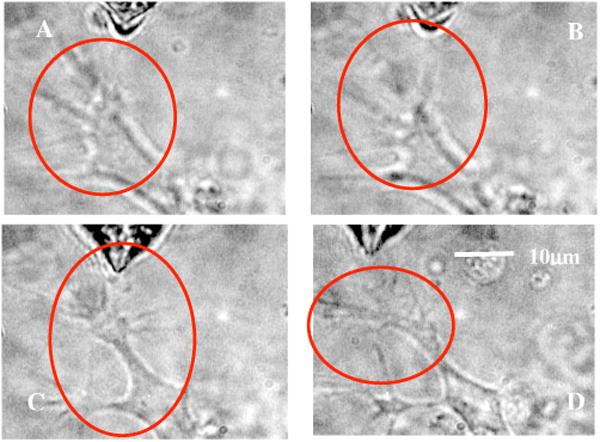
By mode locking the NIR tweezers laser beam, at an average power of 42 mW, the fiber tweezers were transformed into fiber-optic laser scissors and were used to perform nanosurgery at desired locations on the neural processes [circled in Fig. 5(a)]. Figure 5(b) shows the lesion made (marked by arrow) on the axon subsequent to laser nanodissection, which was followed by a resealing process [Fig. 5(c)]. This microscopic-controlled nanodissection of neurons followed by a process of resealing and repair could serve as a useful model system for basic and applied studies on neuronal damage, repair, and regeneration.
Fig. 5.
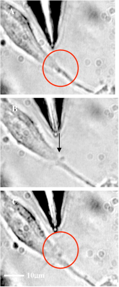
(a) Targeted location on the neural processes (circled) for nanosurgery. (b) Lesion made (marked by arrow) on the axon subsequent to laser nanodissection (after mode locking the NIR tweezers laser beam at 42 mW). (c) Resealing (in the circled region) of the neuronal process after 5 min of surgery.
3.4 Stretching of Neuronal Cells
In order to verify whether the fiber-optic tweezers can exert force on the membrane of the neuronal cell, NG108 cells were grown in suspension and subjected to fiber-optic tweezers. The cells were stretched by the combined action of two forces: an attractive gradient force due to the fiber-optic tweezers at high beam powers pulling the membrane and a scattering force on the membrane as reported in dual-fiber trapping.27 Figures 6(a)–6(d) illustrate stretching of NG108 neuronal cells in suspension using the single-fiber optical stretcher (Video 2). The spherical NG108 neuroblastoma cell in suspension (a), became a tear drop (b) and (c) with elongation along the direction of propagation and compression along the orthogonal direction. Alignment of intracellular dark (high refractive index) material along the direction of laser beam propagation was also observed (c).
Fig. 6.
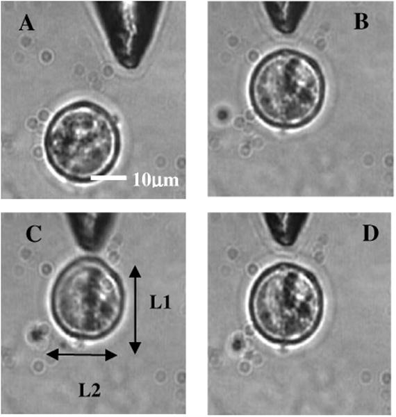
The size of the NG108 neuroblastoma cell, in suspension (a), increased from (b) L1 = 21.15 ± 0.1 μm just before trapping to (c) L1 = 23.00 ± 0.1 μm along the beam axis at trapping power of 120 mW, and decreased in the perpendicular direction from L2 = 21.05 ± 0.1 μm to L2 = 20.65 ± 0.1 μm. (d) After reducing the power, the cell returned to its original shape within 120 ± 40 ms. The values are standard deviation around mean values calculated over six measurements.
Video 2.
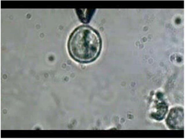
Video showing stretching of an NG108 neuronal cell in suspension using the single-fiber optical stretcher. Alignment of intracellular dark (high refractive index) material along the direction of laser beam propagation can be observed. Repeated stretching could be realized by switching on and off the laser beam. The cell returned to its original shape after switching off the trapping beam. Video corresponds to data in Fig. 6. Resolution is 320 × 240 (MPEG, ∼4 MB). [URL: http://dx.doi.org/10.1117/1.2983663.2].
After reducing the power, the cell returned to its original shape (d) within 120 ± 40 ms. Transportation of the cell along with the movement of the fiber tip after the stretching operation could be carried out (Video 3), ruling out tethering to the substrate. The observed stretching of a cell type with an extensive cytoskeleton suggests an even greater deformation potential for red blood cells, which lack an internal cytoskeleton. The single-fiber stretcher should be able to measure the viscoelastic properties of different biological cells and thus monitor the progress of diseases10 or chemicals that affect the cytoskeleton. It also has an advantage over a dual-fiber optical stretcher because it avoids the crucial requirement of fiber alignment.27
Video 3.
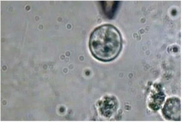
Video showing transportation of a cell along with the movement of the fiber tip after stretching operation; rules out tethering to the substrate. Video corresponds to data related to Fig. 6. Resolution is 720 × 480 (MPEG, ∼3 MB).
4 Conclusions
In conclusion, single-fiber optical trapping in the far and near field was made possible by shaping the axicon-tip cone angle. The fiber-optic tweezers could be used for trapping of cells as well as for controlling the growth rate and direction of neuronal growth cones. Further, single-fiber optical stretching of neuronal cells, in suspension, could be achieved by the combined action of attractive gradient and scattering forces on the cell membrane. By mode locking, the same laser beam coupled to the micro-axicon-tipped fiber could be transformed to optical scissors, enabling nanosurgery of neuronal growth cones. In addition, at high average powers, optical scissors were employed for lysis of a three-dimensionally trapped cell in a fraction of a second. The noninvasive micro-axicontipped optical fiber can be used in multifunctional mode for in-depth trapping, stretching,27 rotation,28,29 sorting,30 microinjection, and ablation as well as for excitation of fluorophores and other light-activated ion channels.31,32 The depth attainable by optical micromanipulation not only is enhanced by a single microfabricated fiber device, but also this technology could lead to sophisticated sensing and imaging capabilities33 that can be applied to live cells.
Acknowledgments
We thank J. Stephens and S. Genc, Univ. of California, Irvine, for careful reading of the manuscript, and V. Garcés-Chávez and K. Dholakia, Univ. of St. Andrews, UK, and H. Rubinsztein-Dunlop, Univ. of Queensland, Australia, for discussions. This work was supported by grants from the United States Air Force (AFOSR No. F9620-00-1-0371).
Contributor Information
Samarendra K. Mohanty, University of California-Irvine, Beckman Laser Institute, Irvine, California 92612.
Khyati S. Mohanty, University of California-Irvine, Beckman Laser Institute, Irvine, California 92612 and University of California-Irvine, Department of Biomedical Engineering, Irvine, California 92612.
Michael W. Berns, University of California-Irvine, Beckman Laser Institute, Irvine, California 92612 and University of California-Irvine, Department of Biomedical Engineering, Irvine, California 92612
References
- 1.Berns MW, et al. Laser microsurgery in cell and developmental biology. Science. 1981;213:505–513. doi: 10.1126/science.7017933. [DOI] [PubMed] [Google Scholar]
- 2.Ashkin A, Dziedzic JM. Optical trapping of viruses and bacteria. Science. 1987;235:1517–1520. doi: 10.1126/science.3547653. [DOI] [PubMed] [Google Scholar]
- 3.Greulich KO. Micromanipulation by Light in Biology and Medicine: The Laser Microbeam and Optical Tweezers. Birkhäuser Verlag; Basel, Switzerland: 1999. [Google Scholar]
- 4.Berns MW. A history of laser scissors (microbeams) Methods Cell Biol. 2007;82C:1–58. doi: 10.1016/S0091-679X(06)82001-7. [DOI] [PubMed] [Google Scholar]
- 5.Grier DG. A revolution in optical manipulation. Nature (London) 2003;424:810–816. doi: 10.1038/nature01935. [DOI] [PubMed] [Google Scholar]
- 6.Asbury CL, Fehr AN, Block SM. Kinesin moves by an asymmetric hand-over-hand mechanism. Science. 2003;302:2130–2134. doi: 10.1126/science.1092985. [DOI] [PMC free article] [PubMed] [Google Scholar]
- 7.Wang MD, Schnitzer MJ, Yin H, Landick R, Gelles J, Block SM. Force and velocity measured for single molecules of RNA ploymerase. Science. 1998;292:902–907. doi: 10.1126/science.282.5390.902. [DOI] [PubMed] [Google Scholar]
- 8.Kellermayer MS, Smith SB, Granier HL, Bustamante C. Folding-unfolding transitions in single titin molecules characterized with laser tweezers. Science. 1997;276:1112–1116. doi: 10.1126/science.276.5315.1112. [DOI] [PubMed] [Google Scholar]
- 9.Kuo SC, Sheetz MP. Force of single kinesin molecules measured with optical tweezers. Science. 1993;260:232–234. doi: 10.1126/science.8469975. [DOI] [PubMed] [Google Scholar]
- 10.Mohanty SK, Uppal A, Gupta PK. Self-rotation of red blood cells in optical tweezers: prospects for high throughput malaria diagnosis. Biotechnol Lett. 2004;26:971–974. doi: 10.1023/b:bile.0000030041.94322.71. [DOI] [PubMed] [Google Scholar]
- 11.Tadir Y, Neev J, Berns MW. Laser in assisted reproduction and genetics. J Assist Reprod Genet. 1992;9:303–305. doi: 10.1007/BF01203948. [DOI] [PubMed] [Google Scholar]
- 12.Ehrlicher A, Betz T, Stuhrmann B, Koch D, Milner V, Raizen MG, Käs J. Guiding neuronal growth with light. Proc Natl Acad Sci USA. 2002;99:16024–16028. doi: 10.1073/pnas.252631899. [DOI] [PMC free article] [PubMed] [Google Scholar]
- 13.Mohanty SK, Sharma M, Panicker M, Gupta PK. Controlled induction, enhancement, and guidance of neuronal growth cones by use of line optical tweezers. Opt Lett. 2005;30:2596–2598. doi: 10.1364/ol.30.002596. [DOI] [PubMed] [Google Scholar]
- 14.Yanik MF, Cinar H, Chisholm AD, Jin Y, Ben-Yakar A. Neurosurgery: functional regeneration after laser axotomy. Nature (London) 2004;432:822. doi: 10.1038/432822a. [DOI] [PubMed] [Google Scholar]
- 15.Taguchi K, Tanaka M, Ikeda M, et al. Theoretical study of an optical levitation using dual beam from optical fibers inserted at an angle. Opt Commun. 2001;33:99. [Google Scholar]
- 16.Hu Z, Wang J, Liang J. Manipulation and arrangement of biological and dielectric particles by a lensed fiber probe. Opt Express. 2004;12:4123–4128. doi: 10.1364/opex.12.004123. [DOI] [PubMed] [Google Scholar]
- 17.Taylor RS, Hnatovsky C. Particle trapping in 3-D using a single fiber probe with an annular light distribution. Opt Express. 2003;11:2775–2782. doi: 10.1364/oe.11.002775. [DOI] [PubMed] [Google Scholar]
- 18.Liu Z, Guo C, Yang J, Yuan L. Tapered fiber optical tweezers for microscopic particle trapping: fabrication and application. Opt Express. 2006;14:12510–12516. doi: 10.1364/oe.14.012510. [DOI] [PubMed] [Google Scholar]
- 19.Mohanty SK, Mohanty KS. Single fiber optical tweezers for manipulation of microscopic objects. Proc SPIE. 2007;6441:644116. [Google Scholar]
- 20.Hoffmann P, Dutoit B, Salathe RP. Comparison of mechanically drawn and protection layer chemically etched optical fiber tips. Ultramicroscopy. 1995;61:165–170. [Google Scholar]
- 21.Mohanty KS, Liberale C, Mohanty SK, Degiorgio V. Indepth fiber optic trapping of low-index microscopic objects. Appl Phys Lett. 2008;92:151113. [Google Scholar]
- 22.Chuang YH, Sun KG, Wang CJ, Huang JY, Pan CL. A simple chemical etching technique for reproducible fabrication of robust scanning near-field fiber probes. Rev Sci Instrum. 1998;69:437–439. [Google Scholar]
- 23.Gelles J, Schnapp BJ, Sheetz MP. Tracking kinesin-driven movements with nanometer-scale precision. Nature (London) 1988;331:450–453. doi: 10.1038/331450a0. [DOI] [PubMed] [Google Scholar]
- 24.Sims CE, Meredith GD, Krasieva TB, Berns MW, Tromberg BJ, Allbritton NL. Laser-micropipet combination for single-cell analysis. Anal Chem. 1998;70:4570–4577. doi: 10.1021/ac9802269. [DOI] [PubMed] [Google Scholar]
- 25.Tirlapur UK, Konig K. Targeted transfection by femtosecond laser. Nature (London) 2002;418:290–291. doi: 10.1038/418290a. [DOI] [PubMed] [Google Scholar]
- 26.Mohanty SK, Sharma M, Gupta PK. Laser assisted microinjection into targeted cells. Biotechnol Lett. 2003;25:895–899. doi: 10.1023/a:1024038609045. [DOI] [PubMed] [Google Scholar]
- 27.Guck J, Ananthakrishnan R, Mahmood H, Moon TJ, Cunningham CC, Käs J. The optical stretcher: a novel laser tool to micromanipulate cells. Biophys J. 2001;81:767–784. doi: 10.1016/S0006-3495(01)75740-2. [DOI] [PMC free article] [PubMed] [Google Scholar]
- 28.Friese MEJ, Nieminen TA, Heckenberg NR, Rubinsztein-Dunlop H. Optical alignment and spinning of lasertrapped microscopic particles. Nature (London) 1998;394:348–350. erratum in Nature (London) 395, 621 (1998) [Google Scholar]
- 29.Dasgupta R, Mohanty SK, Gupta PK. Controlled rotation of biological microscopic objects using optical line tweezers. Biotechnol Lett. 2003;25:1625–1628. doi: 10.1023/a:1025678320136. [DOI] [PubMed] [Google Scholar]
- 30.Hart SJ, Terray AV. Refractive-index-driven separation of colloidal polymer particles using optical chromatography. Appl Phys Lett. 2003;83:5316–5318. [Google Scholar]
- 31.Miller G. Optogenetics: shining new light on neural circuits. Science. 2006;314:1674–1676. doi: 10.1126/science.314.5806.1674. [DOI] [PubMed] [Google Scholar]
- 32.Mohanty SK, Reinscheid RK, Liu X, Okamura N, Krasieva T, Berns MW. In-depth activation of ChR2 sensitized excitable cells with high spatial resolution using two-photon excitation with near-IR laser microbeam. Biophys J. 2008 doi: 10.1529/biophysj.108.130187. in press. [DOI] [PMC free article] [PubMed] [Google Scholar]
- 33.Verma Y, Rao KD, Mohanty SK, Gupta PK. Tapered single mode fiber tip high lateral resolution optical coherence tomography. Laser Phys Lett. 2007;4:686–689. [Google Scholar]


