

Abstract
Objective
The objective of the study was to investigate the feasibility of 7-T shoulder magnetic resonance imaging by developing transmit and receive radiofrequency (RF) coil arrays and exploring RF shim methods.
Materials and Methods
A mechanically flexible 8-channel transmit array and an anatomically conformable 10-channel receive array were designed and implemented. The transmit performance of various RF shim methods was assessed through local flip angle measurements in the right and left shoulders of 6 subjects. The receive performance was assessed through signal-to-noise ratio measurements using the developed 7-T coil and a baseline commercial 3-T coil.
Results
The 7-T transmit array driven with phase-coherent RF shim weights provided adequate B1+ efficiency and uniformity for turbo spin echo shoulder imaging. B1+ twisting that is characteristic of high-field loop coils necessitates distinct RF shim weights in the right and left shoulders. The 7-T receive array provided a 2-fold signal-to-noise ratio improvement over the 3-T array in the deep articular shoulder cartilage.
Conclusions
Shoulder imaging at 7-T is feasible with a custom transmit/receive array either in a single-channel transmit mode with a fixed RF shim or in a parallel transmit mode with a subject-specific RF shim.
Keywords: shoulder, high-field MRI, RF coil array, RF shimming, parallel transmission
Magnetic resonance imaging (MRI) of the shoulder has become the most valuable imaging modality for the evaluation of diseases involving the rotator cuff, articular cartilage, and labroligamentous structures. High signal-to-noise ratio (SNR) is important for the visualization of these structures, many of which are submillimeter in dimension and are only depicted with sufficient contrast on high-resolution images. Their location far from the body periphery and the appeal of applying parallel imaging to reduce scan time underline the need for high baseline SNR. Compared with shoulder MRI at 1.5 T, shoulder MRI at 3 T has been shown to provide greater spatial resolution and superior image quality, resulting in greater diagnostic confidence.1–3 Reports on 7-T musculoskeletal MRI of the knee, ankle, and wrist have demonstrated substantial SNR improvement in the cartilage, synovial fluid, and trabecular bone with superior resolution over 3 T.4–6 Magnetic resonance imaging of the shoulder at 7-T offers similar potential clinical advantages. Greater SNR at 7-T can be translated into higher spatial resolution, which could potentially improve depiction of the intricate shoulder anatomy and its pathology, which, at conventional field strength, is frequently manifested by subtle, difficult-to-visualize discontinuity or surface irregularity in these tissues (eg, linear hyperintense fluid signal within the labrum indicating a labral tear, or fibrillation of the cartilage surface indicating early cartilage degeneration).
High-field imaging of the knee, ankle, and wrist has been successful in part because of convenient encircling coil structures afforded by their anatomic location and small size. For these tissues, reasonably homogeneous radiofrequency (RF) excitation (B1+) can be achieved using a standard azimuthally symmetric, fully surrounding transmit coil such as a birdcage or transverse electromagnetic coil. In contrast to these anatomic targets, high-field shoulder imaging poses unique RF-related challenges7,8 because of its asymmetric location in the body, which makes a fully surrounding transmit coil impractical. This restriction, along with the shoulder’s relatively large volume (compared with the RF wavelength in tissue) and associated high-field RF interference effects9,10 as well as a wide range of subject sizes, necessitates a custom transmit coil and an RF shim scheme to provide adequate B1+ efficiency and homogeneity. High-field shoulder imaging is further complicated by B1+ “twisting,”11–15 where conventional surface coils exhibit transmit and receive profiles that twist in opposite directions away from the geometric center of the element. B1+ twisting implies distinct B1+ patterns in the left and right shoulders, necessitating distinct RF shims.
In this study, we describe the design of an 8-channel transmit array and corresponding RF shim methods for the left and right shoulders at 7-T. We further describe the design and implementation of a dedicated 10-channel receive array that functions inside the transmit array. Both transmit and receive arrays are mechanically flexible to minimize coil-tissue distance over a wide range of subjects. Further, the receive array is constructed on a close-fitting domed structure that conforms to the shoulder anatomy.
MATERIALS AND METHODS
The 7-T images were acquired on a whole-body scanner (MAGNETOM; Siemens, Erlangen, Germany) equipped with an 8-channel parallel transmit system using the developed shoulder coil. The 3-T images were acquired using the body transmit coil and commercially available 4-channel receive-only shoulder coil (small model, Invivo Corp, Gainesville, FL) on a whole-body scanner (TIM Trio; Siemens, Erlangen, Germany). The 3-T coil had the following extents: anterior-posterior, 17 cm; left-right, 12 cm; head-foot, 15 cm. The study was approved by our local institutional review board, and 6 participants (3 male, 3 female; mean [SD] age, 32 [9] years) were scanned after informed written consent was obtained. To provide a measure of participant variability, body mass index (BMI) was recorded and anatomic measurements in the right shoulder were noted in magnetic resonance (MR) images (Table 1).
TABLE 1.
List of Subject BMI and Anatomic Dimensions
| Subject | BMI | A to C Distance, cm |
P to C Distance, cm |
R to C Distance, cm |
|---|---|---|---|---|
| A | 21.3 | 3.8 | 9.2 | 4.8 |
| B | 24.1 | 4.1 | 9.0 | 4.9 |
| C | 23.7 | 4.8 | 9.4 | 5.9 |
| D | 30.1 | 6.0 | 9.8 | 6.7 |
| E | 23.4 | 3.7 | 8.3 | 4.5 |
| F | 21.9 | 3.4 | 7.6 | 4.5 |
| Mean (SD) | 24.1 (3.1) | 4.3 (1.0) | 8.9 (0.8) | 5.2 (0.9) |
A indicates anterior; BMI, body mass index; C, center of the shoulder joint; P, posterior; R, right.
The 7-T Shoulder Transmit Array
Because body coil transmitters are not routinely available at 7-T and to facilitate the control of the B1+ transmit field through RF shimming, a custom 7-T shoulder transmit array was constructed. A fully encircling transmit array would be unwarranted for shoulder excitation because of the large distance between the imaged shoulder and the contralateral coils. We implemented a C-shaped array that surrounded the imaged shoulder (Fig. 1A). The transverse perimeter of the array (64.4 cm) was selected to cover the shoulder of a male participant, while allowing a 2-cm gap between the transmit array and the body to accommodate the receive array (described in a subsequent section). Eight transmit coils (8.7 cm [left-right] × 14.5 cm [head-foot]) were evenly spaced along the perimeter and partially overlapped in the azimuthal direction to minimize mutual inductance.16 Because of the wide variation in human anatomic dimensions,17 2 hinges were added to allow the former to flex between 22 and 33 cm in the anterior-posterior direction. This flexibility assured that a similar distance between the coil and the participant was maintained, which is likely to reduce participant load variability and therefore improve transmit efficiency compared with a rigid design. Coil loading was examined through scattering matrix measurements in 4 participants.
FIGURE 1.
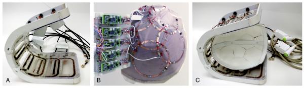
Photographs of the 7-T shoulder transmit array (A), receive array (B), and both arrays (C).
Each coil was tuned to 297.2 MHz using 13 distributed capacitors and matched to 50 Ω through a capacitive transformation while loaded with a shoulder phantom (Fig. 2A). The phantom was molded out of fiberglass to imitate the shoulder contour and filled with agar gel derived from a mixture of water, salt, and corn syrup to approximate shoulder dielectric properties at 297.2 MHz (conductivity, 0.6 S/m; relative permittivity, 47). The transmit array was initially tested in transmit/receive mode and later converted to a detunable transmit array by adding 2 positive-intrinsic-negative diodes in series with each coil. The diodes were forward biased during RF transmission and reverse biased during RF reception. To evaluate diode detuning, S21 was measured through a small shielded double loop probe lightly coupled to an unloaded coil when the diodes were forward biased and reverse biased. For this measurement, coaxial cables were disconnected from the coil.
FIGURE 2.

“Unrolled” layout and electrical schematic of the 7-T shoulder transmit array (A) and receive array (B).
Radiofrequency Shimming
Radiofrequency shimming was investigated as a means to improve transmit efficiency and/or uniformity in the targeted shoulder tissue by adjusting the phase and magnitude of the RF pulse sent to each of the individual transmit coils.18 It should be expected that B1+ twisting and the shoulder’s asymmetric location in the body result in distinct B1+ patterns in the left and right shoulders, requiring distinct shim weights. Full-wave simulations using a current mode expansion with the Dyadic Green functions19,20 were used to demonstrate the effect of B1+ twisting in a shoulder-like configuration, where the transmit array does not fully surround the imaged object. B1+ generated by a transmit array consisting of 8 window coils (or a subset of coils) was calculated in the central transverse plane of an infinite cylindrical phantom (diameter, 13 cm; permittivity, 47; conductivity, 0.6 S/m) using MATLAB software (version 2009b; The Mathworks, Natick, MA). The transmit coils (length, 10 cm; aperture, 5.9 cm) were arranged on a 15-cm diameter former, spaced symmetrically in the azimuthal direction, and were driven with a fixed 45-degree phase offset between adjacent coils. Magnetic coupling among the coils was assumed to be zero in the simulations. We point out that the simulation is intended only to offer an example of the challenges posed by 7-T shoulder imaging and the asymmetry in the B1+ pattern for a conventional excitation scheme with a partially surrounding array. The simulations are a tool that we have developed in-house and that we use to gain insights into full-wave RF behavior and are not intended to represent the exact geometry of the constructed coil.
In addition to the effect of B1+ twisting and shoulder’s asymmetric location, B1+ patterns also vary with subject size and tissue distribution. For these reasons, RF shimming was experimentally investigated in the left and right shoulders of 5 subjects (A through E in Table 1) by acquiring B1+ (flip angle) maps generated by each transmit coil element using the method described in the study of Fautz et al21; 7 transverse slices were acquired with an 8- mm slice thickness and a 12-mm slice gap to allow adequate coverage of relevant shoulder anatomy (parameters are listed in Table 2). Experimental acquisitions were favored over computer simulations because in situ coil placement and complexities such as coil coupling or asymmetric coil current distribution can be difficult to replicate in simulation. Radiofrequency shim schemes were then analyzed offline by calculating the flip angle in multislice B1+ maps resulting from a given scheme according to , where the weights wn specify the amplitude and phase modulation of the driving RF current waveform in the nth channel of transmit array, represents the flip angle corresponding to unit weighting on the nth channel and zero on the others, N is the total number of transmit coils, and is the voxel location. Radio-frequency shim efficacy was assessed by calculating the mean and standard deviation of the flip angles generated in the manually contoured multislice region of interest (ROI) for a given unit input excitation, where . Three shim methods were assessed. (1) Geometric RF shim, denoted by g, where , and is the angle between the geometric center of the nth coil and the location of interest; we targeted the shoulder joint cartilage that was the farthest from the surface because of its rough central location in the shoulder and the general difficulty in depicting this anatomy due to its depth. The drawbacks of the geometrical shim are that it does not consider propagation effects, which can be substantial at 7-T, and that it may be optimal at only a singular spatial position. Nonetheless, we regarded the geometric shim as an appropriate baseline for comparison. (2) Targeted phase-coherent RF shimming improves efficiency by maximizing transmit phase coherence in the ROI,22 denoted by p, where and . One potential drawback of targeted phase-coherent RF shimming is that flip angle uniformity is not explicitly considered. (3) Targeted uniformity shim,23 denoted by u, in which complex transmit weights are calculated by finding the least-squares solution for maximizing flip angle uniformity in the ROI. Targeted uniformity shimming essentially trades efficiency for uniformity by allowing destructive interference to improve uniformity.
TABLE 2.
Pulse Sequence Parameters
| Pulse Sequence | 2D GRE | 3D GRE | 2D GRE | 3D GRE | 2D T1w TSE | 2D T2w TSE | 2D PDw TSE | 2D INTw TSE |
|---|---|---|---|---|---|---|---|---|
| Description | Flip angle mapping |
Temperature mapping |
SNR measurement |
Anatomic imaging |
Anatomic imaging |
Anatomic imaging |
Anatomic imaging |
Anatomic imaging |
| Acquisition plane |
Transverse | Transverse | Transverse, sagittal oblique, and coronal oblique |
Coronal | Sagittal oblique and coronal oblique |
Transverse and sagittal |
Transverse | Coronal |
| FS method | None | None | None | Water excitation |
None | Saturation | Saturation | None |
| Acquired voxel size, mm3 |
3.4 × 3.4 × 8.0 |
2.3 × 2.3 × 5.0 |
0.86 × 0.86 × 3.0 |
0.70 × 0.70 × 0.70 |
0.50 × 0.50 × 3.0 |
0.55 × 0.55 × 2.0 |
0.40 × 0.40 × 3.0 |
0.44 × 0.44 × 2.0 |
| TE, ms | 2.0 | 10 | 4.1 | 3.6 | 13 | 55 | 26 | 30 |
| TR, ms | 3000 | 12 | 200 | 7.2 | 600 | 4030 | 1800 | 3000 |
| Nominal flip angle, degrees |
4 | 10 | 20 | 8 | 160 | 150 | 150 | 170 |
| Bandwidth, hertz per pixel |
490 | 560 | 300 | 445 | 200 | 200 | 245 | 300 |
| Echo train length | 1 | 1 | 1 | 1 | 1 | 11 | 5 | 5 |
| Number of slices | 7 | 48 | 1 | 208 | 16 | 35 | 25 | 21 |
| Field of view, mm2 |
220 × 220 | 300 × 300 | 220 × 220 | 225 × 225 | 192 × 192 | 140 × 140 | 160 × 160 | 140 × 140 |
| Parallel imaging acceleration factor |
None | None | None | 2 | None | 2 | 2 | 2 |
| Acquisition time, s | 399 | 80 | 51 per slice | 257 | 233 | 218 | 206 | 150 |
2D indicates 2-dimensional; 3D, 3-dimensional; FS, fat suppression; GRE, gradient echo; INTw, intermediate-weighted; PDw, proton density-weighted; SNR, signal-to-noise ratio; T1w, T1-weighted; T2w, T2-weighted; TE, echo time; TR, repetition time; TSE, turbo spin echo.
Although subject-specific RF shimming generates a custom B1+ distribution for the given subject, this approach requires additional hardware systems to accommodate parallel transmission. Further, the specific absorption rate (SAR) varies with the selected RF shim weights, which adds a level of complexity in the definition of user-prescribed power limits. As an alternative, we evaluated a composite RF shim approach, which, after the initial flip angle mapping experiments, could be implemented in a standard single-channel transmit mode. In this composite approach, phase-coherent shim weights were calculated from a single optimization using flip angle data from all subjects according to and where s is the subject index and c represents the composite approach. Composite shimming was subsequently realized by feeding the (single-channel) RF amplifier output into an 8-way power splitter whose output phases were realized through coaxial cable segments.
The 7-T Shoulder Receive Array
An array of 10 circular coils was constructed for RF reception. The key element of the receive array was that it fit closely on the subject’s shoulder to provide improved sensitivity through improved coil loading and reduced coil-tissue distance. To accomplish this, a flexible, anatomically correct domed former was designed. To cover the domed structure with coils while simultaneously overlapping neighboring coils to reduce magnetic coupling, elements were arranged such that hexagonal and pentagonal symmetries were maintained between their centers.24 This dictated 3 coils with 8.0-cm diameter and 7 coils with 9.6-cm diameter (Fig. 1). The coils were etched on Pyralux circuit board (DuPont, Fayetteville, NC) to allow mechanical flexibility in the anterior-posterior dimension from 13 to 20 cm. Hexagonal and pentagonal foam patches were fixed to the subject side of the receive array to maintain at least 5 mm of conductor to tissue distance without degrading flexibility. Coverage in the left-right and head-foot directions was 12 and 22 cm, respectively. Preamplifiers and other interface electronics were mounted at the superior end of the receive array to avoid mechanical interference with the transmit array. The coils were tuned to 297.2 MHz and matched to 50 Ω while loaded with the shoulder phantom. Trap circuits at the coil outputs provided active PIN diode controlled detuning during RF transmission (Fig. 2B). A fuse rated to 700 mA was inserted in series with each coil to provide supplementary protection in the event of active detuning failure.
Power Limits
To restrict tissue heating caused by the electric field of the transmit array, RF power limits were determined experimentally through temperature measurements in homogeneous, nonperfused gel phantoms using the proton resonance frequency shift method.25 Measurements were performed in a series of RF heating experiments with the transmit array driven in 3 different configurations: (1) parallel transmit mode, where each coil was driven independently; (2) left composite phase-coherent shim, where the RF output from a single amplifier was divided into 8 equal parts and fed to the transmit array using phase offsets ; and (3) right composite phase-coherent shim, where the transmit array was driven using phase offsets . In an attempt to account for variable subject size, measurements were performed in 2 phantoms: (a) the shoulder phantom described previously and (b) a torsolike elliptical phantom with cross-sectional dimensions of 25 cm (anterior/posterior) × 43 cm (right/left) to represent a larger subject. In all configurations, gradient echo (GRE) phase images were acquired before and after RF application to measure temperature change (imaging parameters are listed in Table 2). The following precautions were taken to reduce temperature measurement error: gradients were disabled during the heating period to minimize drift of the baseline phase; oil phantoms were placed adjacent to the gel phantoms to provide temperature insensitive phase references; and the phantoms were wrapped in 5-mm–thick foam to reduce heat exchange with external air.
In transmit configuration 1, the sequential excitation method described by Cloos et al26 was adopted to experimentally determine conservative power limits in which constructive electric field interference among transmit coils is assumed. In this case, the measured local SAR is given by , where c is a scaling factor related to phantom properties, N is the number of transmit coils, and En is the electric field generated by the nth coil. Local SAR was measured via the temperature maps by applying , where C = 3 kJ kg−1 K−1 is the heat capacity of the phantoms (measured using a KD2 Pro probe; Decagon Devices, Inc, Pullman, WA), is the change in temperature, and τ = 600 seconds is the duration of the RF application. During the RF irradiation period, the time-averaged amplifier output was measured with onboard scanner hardware. Finally, a local SAR limit was established by restricting the time-averaged amplifier output according to , where SARlim was defined as 5 W/kg over a 360-second averaging period. Note that this ensures a 2-fold safety margin over the 10-W/kg limit set by the International Electrotechnical Commission (IEC) (International Standard IEC 60601-2-33 2010). For transmit configuration 1, the maximum local SAR measured in either the shoulder phantom or the torso phantom was 19 W/kg, and the time-averaged power at the amplifier output was 22.5 W per 360 seconds per channel. The local SAR limit was then imposed by restricting the amplifier output to W per 360 seconds per channel. In transmit configuration 2, the amplifier output W per 360 seconds yielded a maximum measured local SAR of 12 W/kg. The local SAR limit was established by restricting the amplifier output to Pc, left = 28.3 W per 360 seconds. Analogously, in transmit configuration 3, the amplifier output limit was set to Pc, right = 20.2 W per 360 seconds.
Shoulder Imaging
To compare the in vivo SNR of the commercial 3-T receive array and the developed 7-T receive array, signal maps were acquired in the transverse plane and 2 oblique planes (sagittal oblique and coronal oblique along the main axis of the humerus) with a GRE pulse sequence (parameters are listed in Table 2). Flip angle calibration was performed in the deep shoulder cartilage (farthest point from the surface) in the transverse slice through the center of the shoulder joint using the method described in the study of Breton et al.27 Noise data were then acquired to allow construction of an SNR map using the optimal array combination method.
To evaluate parallel imaging performance of the 7-T receive array, geometry-factor (g) maps28 were calculated in the 3 cardinal planes from phantom images acquired using the sequence parameters given previously.
Anatomical imaging was demonstrated with the following acquisitions (parameters are listed in Table 2): (1) 3-dimensional (3D) GRE with a water excitation pulse and isotropic resolution, which has been suggested as a replacement for conventional turbo spin echo (TSE) diagnostic shoulder imaging,29–33 (2) T1-weighted TSE, (3) fat-suppressed T2-weighted TSE, (4) fat-suppressed proton density-weighted TSE, and (5) intermediate-weighted TSE.
RESULTS
Full-Wave Simulations
Simulated B1+ maps in Figure 3 reveal the distinction between partial and fully surrounding transmit arrays in the context of shoulder imaging. The elements are driven with the standard birdcage-like phase, which would create a circularly polarized field in the empty coil. Whereas the B1+ field displays nearly mirror symmetry when the transmit array fully surrounds the phantom, the effect of B1+ twisting emerges when the phantom is only partially surrounded by transmit coils. For the polarization of the magnet used in this study, the twisting effect favored the left shoulder (assuming the subject is in the head-first supine position), where constructive interference occurs in the anterior region, which coincides with the shoulder ROI. In the right shoulder, constructive interference occurs in the posterior region, which is farther from the shoulder ROI.
FIGURE 3.
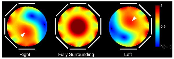
Simulated transverse 7-T B1+ maps in a phantom for 3 transmit array configurations whose elements are highlighted in white. The elements are driven with a birdcage-like phase. Near–mirror symmetry is observed for the fully surrounding transmit array (center panel). The effect of B1+ twisting emerges when the phantom is not fully surrounded by transmit coils (left and right panels). Given the polarity of the 7-T magnet at our facility, constructive interference occurs in the anterior region when the transmit array is on the left side of the phantom (arrowhead, right panel) and in the posterior region when the transmit array is on the right side of the phantom (arrowhead, left panel).
Transmit Array
The quality factor (Q) of the transmit coils was approximately 20 when loaded by the shoulder phantom and 85 in isolation, yielding an unloaded to loaded Q ratio of 4.25. The mean (SD) reflection coefficient measured on the transmit coils while the array was loaded with 4 subjects (BMIs of 20.1, 23.1, 24.4, 26.1) was −20.6 (6.1) dB and the maximum value was −13.1 dB. The mean (SD) transmission coefficient was −14.9 (3.7) dB (maximum value, −8.5 dB) between neighboring coils and −10.8 (2.1) dB (maximum value, −8.4 dB) between the next-nearest neighbor coils. Coupling between all other distant neighbor coil combinations was less than −17 dB.
Radiofrequency Shimming
To allow direct comparison of RF shim methods, all results were normalized such that unit transmit weight w = 1 corresponds to an 18-W hard pulse with 1-millisecond duration. To allow comparison with the literature, transmit efficiency is also presented in terms of the 1-kW hard pulse duration required to generate a 90-degree flip angle. Flip angle magnitude maps from each transmit coil in Figure 4 indicate adequate coverage of the shoulder anatomy and low coupling between the coils. The means (SDs) of the flip angles generated in the right shoulder of subject A using the baseline geometric shim, subject-specific phase-coherent shim, and subject-specific uniformity shim were 52 (15), 63 (15), and 26 (5) degrees, respectively (Figs. 5B, C, and E; Table 3) (flip-angle nonuniformity was 30%, 24%, and 18%). Equivalently, the 1-kW pulse duration required to generate a mean 90-degree flip angle with these 3 shim settings was 232, 192, and 464 μs, respectively. This trend in which phase-coherent shimming provided a moderate efficiency advantage over the geometric shim and a substantial advantage over the uniformity shim, while the uniformity shim provided a moderate uniformity advantage was similar in all subjects. The efficiency penalty associated with uniformity shim was substantial because of the large ROI over which the flip angle was homogenized. The flip angles in the left shoulder were moderately higher than those observed in the right shoulder, given the same RF shim scheme (Fig. 6; Table 3).
FIGURE 4.
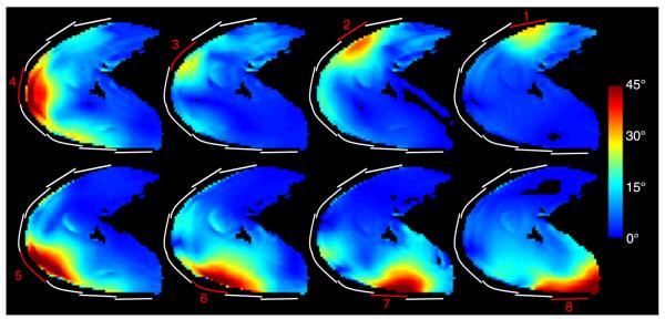
Flip angle magnitude for each transmit coil in the right shoulder of subject B generated using an 18-W hard pulse with 1-millisecond duration on each channel. The approximate location of the transmitting coils are highlighted in red and inactive transmit coils are outlined in white.
FIGURE 5.

Anatomic reference image (A) and flip angle maps (B-F) in the right shoulder of subject A using various RF shim schemes. Approximate transmit coil locations are shown in white, along with corresponding RF shim weights. The ROI for the illustrated slice is highlighted in red in (A). The flip angle and nonuniformity listed at the bottom of each panel were calculated in ROIs in 7 consecutive slices, as described in the methods. The spatial reference point used to determine the geometric shim phases is denoted by an arrowhead in (A) and (B).
TABLE 3.
List of Achieved Flip Angles and Uniformity Using Various Shim Strategies
| Right Shoulder |
Left Shoulder |
||||
|---|---|---|---|---|---|
| Subject | RF Shim Method | Flip Angle, Mean (SD), Degrees | Nonuniformity* | Flip Angle, Mean (SD), Degrees | Nonuniformity* |
| A | P | 62.8 (15.0) | 0.24 | 70.0 (16.0) | 0.23 |
| B | P | 57.0 (15.9) | 0.28 | 60.4 (16.3) | 0.27 |
| C | P | 54.5 (15.0) | 0.27 | 60.5 (20.2) | 0.33 |
| D | P | 50.5 (14.4) | 0.28 | 50.3 (16.2) | 0.32 |
| E | P | 60.1 (11.1) | 0.19 | 65.0 (16.5) | 0.25 |
| A–E | CP | 49.4 (16.4) | 0.33 | 54.8 (19.4) | 0.35 |
| A–E | G | 44.8 (15.0) | 0.33 | 48.1 (14.9) | 0.31 |
| A | U | 26.2 (4.7) | 0.18 | 46.7 (3.8) | 0.08 |
| A–E | CU | 21.7 (4.4) | 0.20 | 37.3 (8.5) | 0.23 |
Nonuniformity is defined as the standard deviation divided by the mean flip angle.
CP indicates composite phase-coherent; CU, composite uniformity; G, geometric; P, subject-specific phase-coherent; U, subject-specific uniformity.
FIGURE 6.

Anatomic reference image (A) and flip angle maps (B-F) in the left shoulder of subject A using various RF shim schemes.
Similarity between subject-specific phase-coherent shim weights, particularly for coils 2 through 7, can be appreciated in Figure 7, indicating that composite phase-coherent shimming is a reasonable approach. Although shim weights for coils 1 and 8 showed a high level of deviation across the subjects, these coils had a relatively low impact on the excitation because they were the farthest from the shoulder ROI. The composite phase-coherent shim provided a flip angle of 55 (14) degrees in subject A, or 13% lower than that provided by the subject-specific phase-coherent shim. Averaged over all subjects, the means (SDs) of the subject-specific, composite phase-coherent, and geometric shims provided flip angles of 57 (14), 49 (16), and 45 (15) degrees (equivalently, 212, 246, and 268 μs 1-kW pulses for a 90-degree flip angle). Figure 8 demonstrates that the composite phase-coherent shim provides similar flip angle efficiency and uniformity in subject F, who was not included in the composite shim optimization. Further, Figure 8 shows that the 3-T body coil was 4 to 5 times more uniform than the developed 7-T local transmit array, although the 3-T body coil required 3.7 times more power than the 7-T array.
FIGURE 7.

Polar plots illustrate RF shim phase offsets for individual subjects and coils in the right (top group) and left (bottom group) shoulders. Tightly grouped colored lines indicate similarity between shim values despite anatomic variability among the subjects. The composite phase-coherent RF shim approach attempts to exploit this similarity (white lines).
FIGURE 8.

Anatomic reference images and flip angle maps in the right and left shoulders of subject F at 7-T using the composite phase-coherent shim (middle row) and at 3-T using body coil (bottom row). All flip angle maps were generated using a 144-W rectangular excitation pulse with 1-millisecond duration, allowing direct comparison with Figures 5 and 6.
Receive Array
The Q of the isolated (loaded) receive coils was approximately 165 (12) for the 9.6-cm coils and 210 (15) for the 8-cm coils, yielding unloaded to loaded Q ratios of approximately 14 for both coil sizes. Diode detuning provided greater than 30-dB isolation between the transmit and receive modes. Coupling between both the neighbor and next-nearest neighbor coils was approximately −10 dB while loaded. The mean value of the off-diagonal entries of the noise correlation matrix was 0.19 (maximum, 0.50; minimum, 0.03).
The 7-T 10-channel receive array provided a 2.1-fold gain in the deep cartilage over the commercial 3-T array (Fig. 9). Greater SNR gains were observed in superficial regions, although it should be noted that SNR values are biased by variable B1+ (recall that the flip angle was calibrated in the deep cartilage at both field strengths). Reciprocal g-factor maps (1/g-factor) in Figure 10 show the fraction of SNR maintained in a parallel imaging acquisition, where unit reciprocal g-factor indicates no noise amplification in parallel imaging reconstruction. The maps indicate an excellent performance for an acceleration rate of 2 in all directions (maximum g-factor, 1.17) and for an acceleration of 3 in the anterior-posterior and left-right directions (maximum g-factor, 1.23). Undesirably high g-factors can be seen for an acceleration rate of 3 or greater in the head-foot direction because of limited diversity of coil sensitivity profiles along this direction.
FIGURE 9.

Three-plane in vivo SNR maps acquired using the developed 7-T 10-channel receive array (top row) and commercial 3 T 4-channel receive array (bottom row). In the deep cartilage (arrows in the left column), the 7-T 10-channel receive array provided a 2.1-fold SNR improvement over the 3-T 4-channel array.
FIGURE 10.

Reciprocal g-factor (1/g) maps in a phantom for parallel imaging acceleration rates (R) of 2 to 4 in the anterior/posterior (top row), left/right (middle row), and head/foot directions (bottom row). The maximum g-factor is indicated in each panel.
Shoulder Imaging
Anatomical images in Figure 11 demonstrate the feasibility of 7-T shoulder imaging using composite phase-coherent B1+ shim weights. The 3-plane (reformatted) 3D GRE images (Figs. 11A–C) illustrate good uniformity and coverage of the entire right shoulder anatomy with an 0.7-mm isotropic resolution, which is higher than that of the typical 3-T acquisitions. Whereas 7-T TSE images were acquired with a resolution similar to 3-T clinical acquisitions (0.40–0.55 mm of in-plane resolution and 2-3 mm of slice thickness), the improved SNR at 7-T should enable higher resolution. A PD-weighted TSE image of the left shoulder in Figure 11D illustrates good image uniformity and allows clear delineation of both articular cartilage layers and the anterior and posterior labra. A T2-weighted TSE image shows adequate image uniformity in the right shoulder joint and depicts a partial anterior labral tear and fluid in the shoulder joint (Fig. 11E). Lack of image uniformity, likely caused by B1+ in homogeneity, can be observed in the deltoid muscle anterolaterally. This subject had a high muscle makeup, which presented a particularly difficult situation in which to achieve high B1+ uniformity. Figure 11F shows a sagittal-oblique T1-weighted TSE image of the right shoulder, which is routinely obtained on all clinical shoulder MR examinations to evaluate for rotator cuff muscle atrophy/fatty infiltration. In this healthy patient, there is normal muscle bulk for the rotator cuff. Figure 11G shows a coronal-oblique T1-weighted TSE image of the left shoulder. The deltoid and supraspinatus muscle tendons are well visualized, as well as the interface between the glenoid and humeral cartilages. Figures 11H to J show several shoulder diseases: hypertrophy of the anterior labrum, posterior labral tear, subchondral cyst formation, and thin glenoid cartilage are seen in Figure 11H; partial-thickness articular surface tear of the posterior fibers of the supraspinatus and a subcortical cyst are seen in Figure 11I; and osteoarthritis and a healed fracture deformity are seen in Figure 11J.
FIGURE 11.

The 7-T anatomic shoulder images. A to C, Reformatted 3D GRE images (0.7-mm isotropic) demonstrate good coverage, uniformity, fat suppression, and high SNR. D, proton density-weighted FSE image of the left shoulder depicts the sublabral foramen (closed white arrow) and anterior and posterior labra (closed black arrows). Good uniformity is observed. The articular cartilage can be visualized in D, E, and G (directly opposed black arrows). E, T2-weighted FSE image of the right shoulder reveals irregularity of the anterior labrum likely reflecting a partial tear (double white arrow). Lack of signal is observed in the peripheral muscles (black arrowhead), likely caused by high B1+. F, T1-weighted TSE image of the right shoulder reveals normal muscle bulk for the rotator cuff in this healthy subject. G, T1-weighted TSE image of the left shoulder depicts the deltoid origin (double black arrow) and the supraspinatus tendon (white arrowhead) as well as the interface between the glenoid and humeral head articular cartilages (directly opposed black arrows). H, T2-weighted TSE image of the left shoulder shows hypertrophy of the anterior labrum (black closed arrow), posterior labral tear (white arrow), subchondral cyst formation (black open arrow), and thin posterior glenoid cartilage (black arrowhead), the latter of which may be related to posterior subluxation of the humeral head. I, T2-weighted TSE image of the left shoulder shows a partial-thickness articular surface tear of the posterior fibers of the supraspinatus (black arrowhead) and a subcortical cyst (double black arrow). J, Intermediate-weighted TSE image shows osteoarthritis manifested by cartilage thinning and osteophyte formation (ellipse) and a healed fracture deformity involving the greater tuberosity and surgical neck of the humerus (bracket).
DISCUSSION
At high field, the short RF wavelength and variation in body size and tissue distribution can lead to B1+ inhomogeneities that can disrupt anatomical imaging in the shoulder. We attempted to maximize B1+ in the target ROI through RF shimming. Of the 4 RF shim methods evaluated (baseline geometric, subject-specific phase-coherent, subject-specific uniformity, and composite phase-coherent), we found the subject-specific phase-coherent method to be the most efficient (mean of 27% advantage in flip angle efficiency over geometric shim), which is to be expected given the nature of the methods tested. Because of the large volume of the shoulder anatomy relative to the wavelength at 7-T, a uniform shim can only be achieved at the expense of flip angle reduction by a factor of 2 or more compared with the phase-coherent shim with the same input power. We therefore found the uniformity shim to excessively restrict fast spin echo (FSE) sequences because of the associated high level of SAR. A modified uniformity shim algorithm in which flip angle uniformity is not strictly enforced and efficiency is prioritized may allow a reasonable tradeoff. Alternatively, elegant excitation techniques, such as slice-selective sinc-like RF pulse segments (“spokes”),34,35 may be essential to achieve high B1+ uniformity in the shoulder. The spokes technique could likely be used with the transmit array proposed here to allow a reasonably short RF pulse duration.36
Subject-specific RF shimming requires parallel transmission,37,38 which is still a developing technique that requires custom scanner hardware, fast B1+ mapping pulse sequences, and, importantly, additional considerations to ensure patient safety because of the shim-dependent SAR. The parallel transmit experiment also necessitates trained users to operate custom scanner interfaces. Recent improvements such as fast B1+ mapping (eg, the study of Nehrke et al39), integrated acquisition, reconstruction, and shimming interfaces, and subject and shim-specific SAR monitoring techniques40–43 can be expected to streamline the parallel transmit examination and may make the proposed composite phase-coherent shim approach less valuable. In the meantime, we calculated composite phase-coherent RF shims a priori, which was appropriate given the high level of similarity across the subjects (Fig. 7), and in agreement with the findings of Bitz et al44 in the thorax and the abdomen. By fixing the shim settings, the developed 7-T shoulder transmit array was used with the scanner in a single-channel transmit mode and the multi-channel transmit array was invisible to the user; the vendor-provided power monitoring system ensured patient safety and the vendor-provided interface was used to prescribe and acquire images. In summary, we found the composite phase-coherent shim to be a favorable compromise between the subject-specific, but time-consuming, parallel transmit experiment and the nominal geometric shim, which is less efficient in terms of B1+ efficiency. Although we found similar B1+ distributions in the 6 subjects scanned here, further investigation is needed to determine the relationship between B1+ and body size and to determine anatomic guidelines in which composite shimming can be successful. This study is therefore limited by the small number of subjects and BMI range.
The developed 7-T shoulder receive array provided a substantial SNR gain (factor of 2 in the deep cartilage) over the commercial 3-T coil. Advantages over the 3-T coil include mechanical flexibility, which is highly desirable because of large anatomic variability in the shoulder and chest. By tightly fitting the 7-T receive array to the body, loading variability is reduced and a higher loaded to unloaded Q ratio is assured. The low g-factors and high SNR provided by the receive array, coupled with the selective excitation inherent to the local transmit array, could potentially allow a significant improvement in spatial resolution. The 7-T receive array also likely benefited from having 10 channels compared with 4 for the 3-T array. However, this benefit can be expected to be most pronounced in the peripheral tissue and less pronounced in the deep cartilage. Therefore, we believe that the SNR comparison in the deep cartilage captures advantages offered by both the improved 7-T coil design and higher field strength. A comparison of 7 and 3 T between coils with identical geometries may have illustrated the SNR benefit due strictly to magnetic field strength, but such an endeavor was beyond the scope of this work.
Given the small size of structures in the shoulder, the SNR advantage at 7-T could be traded for reduced slice thickness, which would then require additional slices to cover the desired volume. This could be troublesome because of SAR constraints, particularly in slice-interleaved 2-dimensional FSE acquisitions (Figs. 11D–G). Fast spin echo sequence customization is therefore warranted to alleviate SAR restrictions while maintaining practical acquisition times by, for example, increasing the length of the refocusing pulses or using hyperecho techniques to allow lower refocusing pulse amplitudes.45 Similar customization may be required for 7-T fat suppression. For example, saturation-based fat suppression can be SAR intensive and perform poorly in regions where the flip angle differs from that prescribed. Water excitation is a viable alternative because of its low power requirement and insensitivity to flip angle variation (Figs. 11A–C). Although the pulse duration necessary for water excitation is typically longer than desired, it is more tolerable at high field because of reduced fat/water phase cycle time (the minimum allowed TE with the water excitation pulse in this work was 3.6 milliseconds).
The distinct B1+ behavior in the left and right shoulders is apparent in the fact that the phase-coherent shim weights did not maintain mirror symmetry, as might be expected given the left/right mirror symmetry of the transmit array. For example, there is a fixed monotonic 45-degree offset between geometric shim weights for coils 3, 4, and 5 in both shoulders (135, 180, and 225 degrees in the right shoulder and 45, 0, 315 degrees in the left shoulder; Figs. 5B, 6B). In contrast, respective phase-coherent shim weights follow a non-monotonic pattern: 169, 180, and 165 degrees for the right shoulder of subject A and 69, 0, and 34 degrees for the left shoulder. The discrepancy between the shim weights for the right and left shoulders is likely caused by B1+ twisting, where individual coils generate circular polarization in localized regions that are offset from the coil midline. For this application, where the shoulder joint is located anterior to the chest-back midline, the left shoulder is in a more favorable position than is the right shoulder to benefit from B1+ twisting, as demonstrated in simulations (Fig. 3) and experiments (Table 3 shows higher flip angles in the left shoulder). Note that transmit elements that lack a current return path or that apply a dielectric substrate such that a plane wave is produced, such as the radiative antenna46 or electric dipole47, do not generate twisted B1+ patterns, which may mitigate the need for distinct left and right shims.
We chose to rely on experimental SAR measurements in a homogeneous, nonperfused phantom to determine power safety limits. The merits of various approaches for determining safe power limits for RF coils are a topic of vigorous discussion in the field. The presented approach is intended to provide a practical means to safely use the prototype coil and gain preliminary experience in 7-T shoulder imaging. Accordingly, it is important to discuss the factors captured and sources of error associated with this coil safety methodology. The main benefit is that the full RF transmission chain, including with coil-specific components such as coaxial cables and cable traps, along with realistic current distribution and coil coupling, is captured in situ. This intrinsically eliminates the need to align and validate computer-based simulations with those in situ. On the other hand, we acknowledge the following experimental uncertainties and assumptions: (1) In our experience, the precision of 7-T MR thermometry in phantoms is approximately 0.2° C, approaching that of invasive fluoroptic temperature probes. This translates to a precision of 1 W/kg for the phantoms used in this study, or less than 10% error in the measured local SAR. (2) The SAR maps were smoothed according to the 17-mm diffusion length associated with the phantoms and 600-second irradiation period that could result in underestimation of local hot spots by approximately 25%. (3) Importantly, SAR in a homogeneous phantom may differ from that in a multicompartment model representative of the shoulder anatomy. Computer-based SAR calculations demonstrated an increase of up to 25% in local SAR in a heterogeneous head compared with a homogeneous model.48 Although this result cannot be applied with impunity to the shoulder anatomy, we regard it as an insightful starting point on which a safety margin can be based. On the basis of these factors, we implemented a SAR limit of 5 W/kg to ensure a 2-fold safety margin against that dictated by the IEC, which is likely greater than the acknowledged experimental uncertainties and potential discrepancy between phantom and in vivo heating. Of course, this method does not take advantage of computer-based SAR prediction models, which may provide justification for a reduced safety margin, and the opportunity to evaluate impactful variables such as coil-subject positioning49 and heterogeneous shoulder models.
In conclusion, we demonstrated the feasibility of 7-T shoulder imaging using custom transmit and receive arrays. The 8-channel transmit array provided sufficient B1+ uniformity and efficiency for multislice FSE acquisitions. The 10-channel receive array provided a substantial SNR gain over the commercial 3-T receive array. The mechanical flexibility of both arrays minimized coil-tissue distance, which, in the case of the transmit array, improved efficiency. Although we have demonstrated adequate B1+ uniformity and increased SNR with the developed coil, the utility of 7-T shoulder imaging must be further evaluated in patients with diseases. Such an endeavor requires pulse sequence customization to generate appropriate tissue contrast. It is recognized that, while GRE sequences can be readily applied at high field, FSE sequences must be carefully customized to accommodate prolonged T1 relaxation times, reduced T2 decay times, and greater SAR at 7-T. Recent literature suggests that 7-T protocols will soon provide a comprehensive variety of clinically relevant pulse sequences and tissue contrasts,5,22,50 along with the potential for improved spatial resolution.
ACKNOWLEDGMENT
The authors thank Leeor Alon and Martijn Cloos for insightful discussions and analysis of temperature mapping data, Riccardo Lattanzi for supplying the dyadic Green’s functions MATLAB code, Cornel Stefanescu for construction of the coil and phantom formers, and Gene Young Cho for construction of the shoulder phantom.
Conflicts of interest and sources of funding: Supported partially by research grant R01EB002568 from the National Institutes of Health, Bethesda, MD.
Footnotes
The authors report no conflicts of interest.
REFERENCES
- 1.Magee TH, Williams D. Sensitivity and specificity in detection of labral tears with 3.0-T MRI of the shoulder. AJR Am J Roentgenol. 2006;187:1448–1452. doi: 10.2214/AJR.05.0338. [DOI] [PubMed] [Google Scholar]
- 2.Magee T, Williams D. 3.0-T MRI of the supraspinatus tendon. AJR Am J Roentgenol. 2006;187:881–886. doi: 10.2214/AJR.05.1047. [DOI] [PubMed] [Google Scholar]
- 3.La Rocca Vieira R, Rybak LD, Recht M. Technical update on magnetic resonance imaging of the shoulder. Magn Reson Imaging Clin N Am. 2012;20:149–161. doi: 10.1016/j.mric.2012.01.005. [DOI] [PubMed] [Google Scholar]
- 4.Juras V, Welsch G, Bar P, et al. Comparison of 3T and 7T MRI clinical sequences for ankle imaging. Eur J Radiol. 2012;81:1846–1850. doi: 10.1016/j.ejrad.2011.05.023. [DOI] [PubMed] [Google Scholar]
- 5.Regatte RR, Schweitzer ME. Ultra-high-field MRI of the musculoskeletal system at 7.0T. J Magn Reson Imaging. 2007;25:262–269. doi: 10.1002/jmri.20814. [DOI] [PubMed] [Google Scholar]
- 6.Chang G, Friedrich KM, Wang L, et al. MRI of the wrist at 7 tesla using an eight-channel array coil combined with parallel imaging: preliminary results. J Magn Reson Imaging. 2010;31:740–746. doi: 10.1002/jmri.22072. [DOI] [PMC free article] [PubMed] [Google Scholar]
- 7.Kraff O, Orzada S, Choukri M, et al. 7 Tesla MRI of the Shoulder and Upper Extremities Using an 8-Channel Tx/Rx Coil. Proceedings of the 20th Annual Meeting of ISMRM; Melbourne, Australia. 5-11 May 2012.p. 306. [Google Scholar]
- 8.Brown R, Zhang B, Deniz CM, et al. Detunable Transmit Array and Flexible Receive Array for 7T Shoulder Imaging. Proceedings of the 20th Annual Meeting of ISMRM; Melbourne, Australia. 5-11 May 2012.p. 428. [Google Scholar]
- 9.Collins CM, Liu W, Schreiber W, et al. Central brightening due to constructive interference with, without, and despite dielectric resonance. J Magn Reson Imaging. 2005;21:192–196. doi: 10.1002/jmri.20245. [DOI] [PubMed] [Google Scholar]
- 10.Van de Moortele PF, Akgun C, Adriany G, et al. B(1) destructive interferences and spatial phase patterns at 7-Twith a head transceiver array coil. Magn Reson Med. 2005;54:1503–1518. doi: 10.1002/mrm.20708. [DOI] [PubMed] [Google Scholar]
- 11.Keltner JR, Carlson JW, Roos MS, et al. Electromagnetic fields of surface coil in vivo NMR at high frequencies. Magn Reson Med. 1991;22:467–480. doi: 10.1002/mrm.1910220254. [DOI] [PubMed] [Google Scholar]
- 12.Wiggins GC, Duan Q, Lattanzi R, et al. B1+ and SNR Optimization of High Field RF Coils Through Offsetting of Transmit and Receive Elements. Proceedings of the 17th Annual Meeting of ISMRM; Honolulu, HI. 18–24 April 2009.p. 2951. [Google Scholar]
- 13.Collins CM, Wang Z. Calculation of radiofrequency electromagnetic fields and their effects in MRI of human subjects. Magn Reson Med. 2011;65:1470–1482. doi: 10.1002/mrm.22845. [DOI] [PMC free article] [PubMed] [Google Scholar]
- 14.Vaidya MV, Sodickson DK, Brown R, et al. B1+ and B1− field pattern dependence on the electrical properties of the sample and the static magnetic field strength. Proceedings of the 20th Annual Meeting of ISMRM; Melbourne, Australia. 5-11 May 2012.p. 2796. [Google Scholar]
- 15.Zhang B, Sodickson DK, Lattanzi R, et al. Why Does the Radiative Antenna Have No B1 Twisting at 7T? Framework for and Applications of a Conceptual “mirror current” model of coil-tissue interactions. Proceedings of the 20th Annual Meeting of ISMRM; Melbourne, Australia. 5-11 May 2012.p. 2816. [Google Scholar]
- 16.Roemer PB, Edelstein WA, Hayes CE, et al. The NMR phased array. Magn Reson Med. 1990;16:192–225. doi: 10.1002/mrm.1910160203. [DOI] [PubMed] [Google Scholar]
- 17.Tilley AR. The Measure of Man and Woman. The Whitney Library of Design; New York, NY: 1993. pp. 11–14. [Google Scholar]
- 18.Hoult DI, Phil D. Sensitivity and power deposition in a high-field imaging experiment. J Magn Reson Imaging. 2000;12:46–67. doi: 10.1002/1522-2586(200007)12:1<46::aid-jmri6>3.0.co;2-d. [DOI] [PubMed] [Google Scholar]
- 19.Schnell W, Renz W, Vester M, et al. Ultimate signal-to-noise-ratio of surface and body antennas for magnetic resonance imaging. IEEE T Antenn Propag. 2000;48:418–428. [Google Scholar]
- 20.Lattanzi R, Grant AK, Polimeni JR, et al. Performance evaluation of a 32-element head array with respect to the ultimate intrinsic SNR. NMR Biomed. 2010;23:142–151. doi: 10.1002/nbm.1435. [DOI] [PMC free article] [PubMed] [Google Scholar]
- 21.Fautz HP, Vogel M, Gross P, et al. B1 Mapping of Coil Arrays for Parallel Transmission. Proceedings of the 16th Annual Meeting of ISMRM; Toronto, Canada. 3–9 May 2008.p. 1247. [Google Scholar]
- 22.Metzger GJ, Snyder C, Akgun C, et al. Local B1+ shimming for prostate imaging with transceiver arrays at 7T based on subject-dependent transmit phase measurements. Magn Reson Med. 2008;59:396–409. doi: 10.1002/mrm.21476. [DOI] [PMC free article] [PubMed] [Google Scholar]
- 23.Mao W, Smith MB, Collins CM. Exploring the limits of RF shimming for highfield MRI of the human head. Magn Reson Med. 2006;56:918–922. doi: 10.1002/mrm.21013. [DOI] [PMC free article] [PubMed] [Google Scholar]
- 24.Wiggins GC, Triantafyllou C, Potthast A, et al. 32-channel 3 Tesla receive-only phased-array head coil with soccer-ball element geometry. Magn Reson Med. 2006;56:216–223. doi: 10.1002/mrm.20925. [DOI] [PubMed] [Google Scholar]
- 25.Ishihara Y, Calderon A, Watanabe H, et al. A precise and fast temperature mapping using water proton chemical shift. Magn Reson Med. 1995;34:814–823. doi: 10.1002/mrm.1910340606. [DOI] [PubMed] [Google Scholar]
- 26.Cloos M, Alon L, Chen G, et al. Rapid RF Safety Evaluation for Transmit-Array Coils. Proceedings of the 21st Annual Meeting of ISMRM; Salt Lake City, UT. 20-26 April 2013.p. 286. [Google Scholar]
- 27.Breton E, McGorty K, Wiggins GC, et al. Image-guided radio-frequency gain calibration for high-field MRI. NMR Biomed. 2010;23:368–374. doi: 10.1002/nbm.1471. [DOI] [PMC free article] [PubMed] [Google Scholar]
- 28.Pruessmann KP, Weiger M, Scheidegger MB, et al. SENSE: sensitivity encoding for fast MRI. Magn Reson Med. 1999;42:952–962. [PubMed] [Google Scholar]
- 29.Magee T. Can isotropic fast gradient echo imaging be substituted for conventional T1 weighted sequences in shoulder MR arthrography at 3 Tesla? J Magn Reson Imaging. 2007;26:118–122. doi: 10.1002/jmri.21000. [DOI] [PubMed] [Google Scholar]
- 30.Lee MJ, Motamedi K, Chow K, et al. Gradient-recalled echo sequences in direct shoulder MR arthrography for evaluating the labrum. Skeletal Radiol. 2008;37:19–25. doi: 10.1007/s00256-007-0398-z. [DOI] [PubMed] [Google Scholar]
- 31.Oh DK, Yoon YC, Kwon JW, et al. Comparison of indirect isotropic MR arthrography and conventional MR arthrography of labral lesions and rotator cuff tears: a prospective study. AJR Am J Roentgenol. 2009;192:473–479. doi: 10.2214/AJR.08.1223. [DOI] [PubMed] [Google Scholar]
- 32.Xia Y, Zheng S. Reversed laminar appearance of articular cartilage by T1-weighting in 3D fat-suppressed spoiled gradient recalled echo (SPGR) imaging. J Magn Reson Imaging. 2010;32:733–737. doi: 10.1002/jmri.22278. [DOI] [PMC free article] [PubMed] [Google Scholar]
- 33.Jung JY, Yoon YC, Choi SH, et al. Three-dimensional isotropic shoulder MR arthrography: comparison with two-dimensional MR arthrography for the diagnosis of labral lesions at 3.0 T. Radiology. 2009;250:498–505. doi: 10.1148/radiol.2493071548. [DOI] [PubMed] [Google Scholar]
- 34.Saekho S, Yip CY, Noll DC, et al. Fast-kz three-dimensional tailored radio-frequency pulse for reduced B1 inhomogeneity. Magn Reson Med. 2006;55:719–724. doi: 10.1002/mrm.20840. [DOI] [PMC free article] [PubMed] [Google Scholar]
- 35.Ulloa J, Irarrazaval P, Hajnal J. Exploring 3D RF shimming for slice selective imaging. Proceedings of the 13th Annual Meeting of ISMRM; Miami, FL. 7-13 May 2005.p. 21. [Google Scholar]
- 36.Setsompop K, Alagappan V, Gagoski B, et al. Slice-selective RF pulses for in vivo B1+ inhomogeneity mitigation at 7 tesla using parallel RF excitation with a 16-element coil. Magn Reson Med. 2008;60:1422–1432. doi: 10.1002/mrm.21739. [DOI] [PMC free article] [PubMed] [Google Scholar]
- 37.Zhu YD. Parallel excitation with an array of transmit coils. Magn Reson Med. 2004;51:775–784. doi: 10.1002/mrm.20011. [DOI] [PubMed] [Google Scholar]
- 38.Katscher U, Bornert P, Leussler C, et al. Transmit SENSE. Magn Reson Med. 2003;49:144–150. doi: 10.1002/mrm.10353. [DOI] [PubMed] [Google Scholar]
- 39.Nehrke K, Bornert P. DREAM–a Novel Approach for Robust, Ultra-Fast, Multi-Slice B1 Mapping. Proceedings of the 20th Annual Meeting of ISMRM; Melbourne, Australia. 5–11 May 2012.p. 605. [Google Scholar]
- 40.Eichfelder G, Gebhardt M. Local specific absorption rate control for parallel transmission by virtual observation points. Magn Reson Med. 2011;66:1468–1476. doi: 10.1002/mrm.22927. [DOI] [PubMed] [Google Scholar]
- 41.Zhang X, Schmitter S, Van de Moortele P, et al. From complex B1 mapping to local SAR estimation for human brain MR imaging using multi-channel transceiver coil at 7T. IEEE Trans Med Imaging. 2013;32:1058–1067. doi: 10.1109/TMI.2013.2251653. [DOI] [PMC free article] [PubMed] [Google Scholar]
- 42.Voigt T, Homann H, Katscher U, et al. Patient-individual local SAR determination: in vivo measurements and numerical validation. Magn Reson Med. 2012;68:1117–1126. doi: 10.1002/mrm.23322. [DOI] [PubMed] [Google Scholar]
- 43.van den Bergen B, Stolk CC, Berg JB, et al. Ultra fast electromagnetic field computations for RF multi-transmit techniques in high field MRI. Phys Med Biol. 2009;54:1253–1264. doi: 10.1088/0031-9155/54/5/010. [DOI] [PubMed] [Google Scholar]
- 44.Bitz AK, Brote I, Orzada S, et al. Comparison of Simulation-Based and Measurement-Based RF Shimming for Whole-Body MRI at 7 Tesla. Proceedings of the 18th Annual Meeting of ISMRM; Stockholm, Sweden. 1–7 May 2010.p. 4720. [Google Scholar]
- 45.Hennig J, Weigel M, Scheffler K. Multiecho sequences with variable refocusing flip angles: optimization of signal behavior using smooth transitions between pseudo steady states (TRAPS) Magn Reson Med. 2003;49:527–535. doi: 10.1002/mrm.10391. [DOI] [PubMed] [Google Scholar]
- 46.Raaijmakers AJ, Ipek O, Klomp DW, et al. Design of a radiative surface coil array element at 7-T: the single-side adapted dipole antenna. Magn Reson Med. 2011;66:1488–1497. doi: 10.1002/mrm.22886. [DOI] [PubMed] [Google Scholar]
- 47.Wiggins GC, Zhang B, Lattanzi R, et al. The Electric Dipole Array: an Attempt to Match the Ideal Current Pattern for Central SNR at 7 Tesla. Proceedings of the 20th Annual Meeting of ISMRM; Melbourne, Australia. 5-11 May 2012.p. 541. [Google Scholar]
- 48.Wolf S, Diehl D, Gebhardt M, et al. SAR simulations for high-field MRI: how much detail, effort, and accuracy is needed? Magn Reson Med. 2013;69:1157–1168. doi: 10.1002/mrm.24329. [DOI] [PubMed] [Google Scholar]
- 49.Kozlov M, Turner R. Effects of Head Size and Position on SAR. Proceedings of the 18th Annual Meeting of ISMRM; Stockholm, Sweden. 1-7 May 2010.p. 3875. [Google Scholar]
- 50.Ellermann J, Goerke U, Morgan P, et al. Simultaneous bilateral hip joint imaging at 7 Tesla using fast transmit B(1) shimming methods and multichannel transmission—a feasibility study. NMR Biomed. 2012;25:1202–1208. doi: 10.1002/nbm.2779. [DOI] [PMC free article] [PubMed] [Google Scholar]