Abstract
This brief perspective focuses on recent advances in the design of functional soft materials that are based on confinement of low molecular weight liquid crystals (LCs) within micrometer-sized droplets. While the ordering of LCs within micrometer-sized domains has been explored extensively in polymer-dispersed LC materials, recent studies performed with LC domains with precisely defined size and interfacial chemistry have unmasked observations of confinement-induced ordering of LCs that do not follow previously reported theoretical predictions. These new findings, which are enabled in part by advances in the preparation of LCs encapsulated in polymeric shells, are opening up new opportunities for the design of soft responsive materials based on surface-induced ordering transitions. These materials are also providing new insights into the self-assembly of biomolecular and colloidal species at defects formed by LCs confined to micrometer-sized domains. The studies presented in this perspective serve additionally to highlight gaps in knowledge regarding the ordering of LCs in confined systems.
Keywords: Liquid crystals, micrometer-sized droplets, functional materials, self-assembly, topological defects, ordering transitions, amphiphiles, chemically patterned microparticles
1. Introduction
Liquid crystals (LCs) are a phase of matter that combines properties commonly associated with crystalline solids (long-range orientational order) and isotropic liquids (high levels of molecular mobility).1–4 The orientational ordering of molecules in LCs leads to anisotropic properties (optical, mechanical, transport). Of particular relevance to this perspective, the ordering of LCs near interfaces is also known to be remarkably sensitive to interfacial interactions, including those arising from hydrogen bonding, van der Waals interactions, metalligand coordination and electrical double layers.5–8
This perspective is focused on nematic LCs confined within micrometer-sized droplets that are dispersed within a second immiscible medium. While dispersions of nematic LCs have been widely investigated within continuous polymeric phases (so-called “polymer dispersed liquid crystals” (PDLCs)),9–11 more recently, investigations based on systems that permit precise control of LC droplet size and interfacial chemistry have revealed unanticipated size-dependent ordering of LCs. It is these recent findings that motivate this perspective, as they are providing the opportunity to create new designs of functional materials based on LC droplets.
As noted above, this perspective describes studies that have systematically investigated the effects of changes in LC droplet size and interfacial chemistry on LC ordering and functional properties. Where helpful to a reader, however, we briefly describe past studies involving PDLCs to highlight gaps in knowledge addressed by the recent studies. We also note that the majority of the studies reported in this perspective deal with LC droplets dispersed in aqueous phases. The interfaces of the water-dispersed LC droplets are decorated with molecular species that possess a diversity of chemical functionality that goes well beyond those investigated previously (biological lipids, surfactants, proteins, polyelectrolytes, etc). The majority of studies falling within the above-stated scope of this perspective have been reported by our own research group. However, where relevant to the scope of this article, we also describe work reported by other laboratories.
A key aspect of the work described below involves elucidation of the ordering of LCs within dispersed phases, and specifically, identification of the director configuration within LC droplets. As an introduction to this topic, Figure 1 displays bright field, polarized light micrographs and schematic illustrations of nematic LC in several common configurations encountered in droplets (and of relevance to the studies presented in this perspective). We point out that Figure 1 shows one orientation for each LC droplet configuration, and that other orientations of the LC droplets will generate distinct optical signatures (with the exception of the rotationally symmetric radial configuration).2, 10, 12–15 Within the droplets, the average orientations of the molecules forming the nematic LC are described by a director (n). For example, Figure 1A shows a so-called bipolar configuration of the LC droplet. In this configuration, the director is aligned tangentially to the droplet interface and two diametrically opposite point defects (“boojums”) are present at the poles of each LC droplet.10, 13, 17–20 The interested reader is directed elsewhere for detailed descriptions of the optical signatures of LC droplets in various other director configurations.2, 10, 12–15
Figure 1.
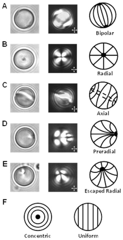
(A–E) Bright field (left) and polarized light (middle) micrographs and corresponding schematic illustrations (right) of director configurations commonly observed for micrometer-sized droplets of nematic LC. The droplets displayed in the micrographs are 8-μm-diameter droplets of nematic 4′-pentyl-4-cyanobiphenyl (5CB) dispersed in either (A) water or (B–E) aqueous dispersions of the biological lipids. (F) Schematic illustrations of other possible director configurations of micrometer-sized LC droplets. The solid black lines within the droplet boundaries in the illustrations represent the orientation of the LC director and the black spots represent defects. Double headed arrows in polarized light micrographs indicate the orientation of the crossed polarizers. Reproduced with permission.16
As background to the recent observations of size-dependent ordering of LCs in droplets that are detailed below, here we briefly introduce a common formulation of the free energy of a LC droplet and then summarize key predictions that follow from the description. In short, the equilibrium director configuration within a LC droplet is governed by a delicate energetic balance that involves surface and volumetric contributions. The free energy (F) of a LC droplet can be expressed as:
| (1) |
where Fhomogeneous is the free energy of an unstrained bulk LC (typically expressed as a function of the orientational order parameter of the LC, and neglected in analytical models of relative energies of two director configurations), A is the surface area of a droplet, V the volume of a droplet, fs and fe are the surface anchoring energy and elastic free energy densities, respectively, and ffield is the free energy density due to external fields (e.g., an electric field).10 The last term in equation 1 describes the contribution of defects to the free energy, as discussed in detail below. We note that in the discussion below we assume the LC droplet shape to be spherical and independent of the internal ordering of the LC. This approximation is a good one for thermotropic LCs dispersed in water as the interfacial tensions are high (typically 10−3 to 10−2 J/m2).
The surface anchoring energy of the LC droplet (second term in equation 1) characterizes the energetic penalty associated with deviations of the nematic director from its preferred alignment at the droplet interface (easy axis; set by the interfacial chemistry). The surface anchoring energy density (fs) is often approximated using the single-constant Rapini and Papoular equation:
| (2) |
where φ is the angle between the director (n) and easy axis, and W is surface anchoring energy per unit area.21 Typical values of W range from 10−6 to 10−5 J/m2,10, 22 a range that is at least two orders of magnitude smaller than common values of interfacial tension for LC droplets dispersed in water (see above).23, 24
The elastic free energy of the LC droplet (third term in equations 1) is the energetic penalty associated with strain of the LC. The elastic free energy density (fe) can be described by the Frank-Oseen equation:
| (3) |
where K11, K22, K33 (which are sometimes also labeled as K1, K2, and K325–27) and K24 are elastic constants associated with splay, twist, bend, and saddle-splay strain, respectively.4, 28, 29 We also comment that a fifth elastic constant not shown in equation 3 is the splay-bend elastic constant (K13), which is typically neglected because it involves higher order derivatives of n.30, 31
Two external fields frequently applied to LC droplets are electric and magnetic fields. The free energy density due to these two external fields (ffield; fourth term in equation 1) can be expressed as:
| (4) |
where the first term is the energy density due to an applied electric field, and εo is the free space permittivity, Δε is the nematic dielectric anisotropy, and E is the local electric field inside a droplet (usually different from the applied field).10, 29, 32, 33 The second term in equation 4 is the energy density due to an applied magnetic field, and μo is the free space permeability, Δχ is diamagnetic anisotropy, and B is the local magnetic field inside a droplet.
The fifth term in equation 1 is the free energy contribution from topological defects, where fd and Vd are the free energy density and volume of defects, respectively. Defects are localized regions of LC that partially “melt” in response to a high local elastic free energy density of the LC. Specifically, the cores of defects, which are typically about 10 nm in size, possess levels of orientational order that are lower than that of the bulk LC.34, 35 In general, defects are easily identified in bright field micrographs of LC droplets because the defect cores, although nanoscopic in size, possess refractive indices that differ substantially from that of the surrounding LC and strongly scatter light (see Figure 1, left column). Defects, therefore, are frequently used to aid in characterization of the director configuration of LC droplet.15 As discussed below, the contribution of defects to the free energy of a droplet is typically two orders of magnitude lower than the surface anchoring and elastic energies and, therefore, often neglected in the evaluation of equation 1.14 Despite their small “core” energies, however, defects appear to play an important role in mediating the interactions of LC droplets with some biological amphiphiles14, 16 as well as colloidal species in LC-templated material synthesis36 (see below).
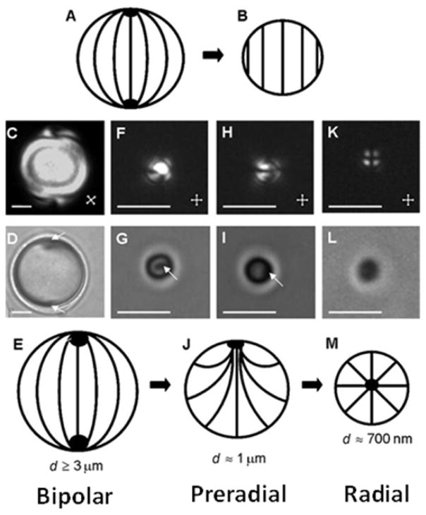
The above formulation of the free energy of a LC droplet has been widely used to predict the size-dependent ordering of nematic LC within droplets. Historical descriptions have typically neglected the contribution saddle-splay strain (K24) to the elastic energy (although more recent studies indicate that it can play a role in the relative stability of droplet director configurations, a point that we expand on below)10, 14, 16, 37 and applied the “one elastic constant approximation” (i.e., K = K11 = K22 = K33).4, 10 With these approximations, equations 1 through 3 predict that the elastic energy of a LC droplet scales with the droplet radius (~ KR) and the surface anchoring energy scales with the square of the droplet radius (~ WR2). In the absence of applied fields and neglecting defect energies, these two contributions to the free energy lead to the expectation that droplets with R ≪ K/W will exhibit a uniform director profile free of strain (see Figure 4B below) whereas larger droplets will satisfy the surface anchoring and incur a free energy penalty associated with strain.22, 38 Because typical elastic constants and surface anchoring energies per unit area are 10−11 N and 10−5 J/m2, respectively,16, 25 this scaling argument predicts a cross-over in free energy/droplet configuration for droplets with sizes of ~1 μm. As will be discussed below, recent experimental measurements have led to observations of size-dependent order that are not consistent with these historical predictions, thus leading to a reexamination of the energetics that control the size-dependent ordering of LC droplets.37, 39
Figure 4.
Size-dependent ordering within LC. (A and B) Schematic illustrations of the bipolar (A) and uniform (B) ordering of LCs predicted from scaling arguments. (C, F, H, K) Polarized light and (D, G, I, L) bright field optical micrographs of polymer-encapsulated 5CB droplets with (C, D) diameters of 8.0 ± 0.2 μm and bipolar LC ordering, (F–I) diameters of 1.0 ± 0.2 μm and preradial LC ordering ((F and G) show the end on views of the preradial ordering; (H and I) show side views), and (K, L) diameters of 0.70 ± 0.08 μm and radial LC ordering. Point defects in the LCs are indicated by white arrows. Schematic illustrations (E, J, and M) show bipolar, preradial, and radial ordering of the LC droplets, respectively. The scale bars are 2 μm for (C, D, and F–I), and 1 μm for (K, L). Reproduced with permission.37
The remainder of this perspective is organized into three sections. The first section details recent studies that have revealed size-dependent ordering of LCs within micrometer-sized droplets that possess precisely defined sizes and interfacial chemistry. In the second section, we highlight how these observations underlie new, emerging designs of functional LC materials that respond to remarkably low concentrations of specific biomolecular species. These studies are also revealing the importance of interactions of molecular species at defects in determining the configurations of LC droplets. The third section addresses the use of LC droplets as templates for synthesis of spherical and non-spherical polymeric particles with chemical patches, highlighting again the diversity of functional properties that can be engineered based on the presence of defects in LCs. We conclude the perspective by offering thoughts regarding possible future directions of research involving LC droplet-based materials, and we also discuss gaps in knowledge that need to be addressed to facilitate progress in design of LC droplet-based materials.
2. Recent Observations of Size-Dependent Ordering of LCs in Micrometer-Sized Droplets
Size-Dependent Ordering of LCs in the Droplets of PDLCs
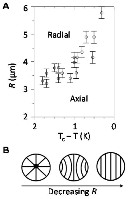
Here we briefly discuss past observations of size-dependent ordering of LCs in droplets of PDLCs to provide a historical perspective and highlight gaps in knowledge addressed by the more recent experimental studies that are the focus of this perspective. Size-dependent changes in the director configuration of micrometer-sized droplets of LC dispersed in polymer matrices have been characterized both experimentally32, 40 and predicted theoretically.29, 33 For example, Figure 2A shows an experimentally measured phase diagram for droplets of a nematic LC called E7 dispersed in a polyurethane matrix that causes homeotropic anchoring of the LC.32 It was observed that a decrease in LC droplet size below a critical value caused a spontaneous radial-to-axial ordering transition. A second transition from an axial to a uniform director was predicted but was not observed in experiments (Figure 2B). We also comment here that past studies have demonstrated that application of an electric field can trigger a radial-to-axial ordering transition within the LC droplets. The strength of the applied field needed to trigger the transitions is dependent on the size of the LC droplets in the PDLC.29, 32, 33, 40
Figure 2.
(A) Experimental phase diagram of the preferred configuration of nematic droplets of E7 dispersed in a polyurethane matrix as a function of temperature (T) and droplet radius (R). Tc is the nematic-to-isotropic clearing temperature (303 K for this system). (B) Schematic illustrations of the director configuration predicted as a function of decreasing R. Reproduced with permission.32
While the studies summarized above report size-dependent ordering of LCs in PDLCs, we comment that the processes of phase separation leading to formation of LC droplets in PDLCs impact the composition of the LC (note that the nematic-to-isotropic clearing temperature of the LC in Figure 2 is 303 K whereas the clearing temperature of pure E7 is 30 K higher). This compositional uncertainty is resolved in more recent experiments performed using water-dispersed LC droplets. We also note that recent experiments also permit precise control over the interfacial anchoring of the LC.37, 39
Preparation of LC Droplets with Precise Size and Interfacial Chemistry
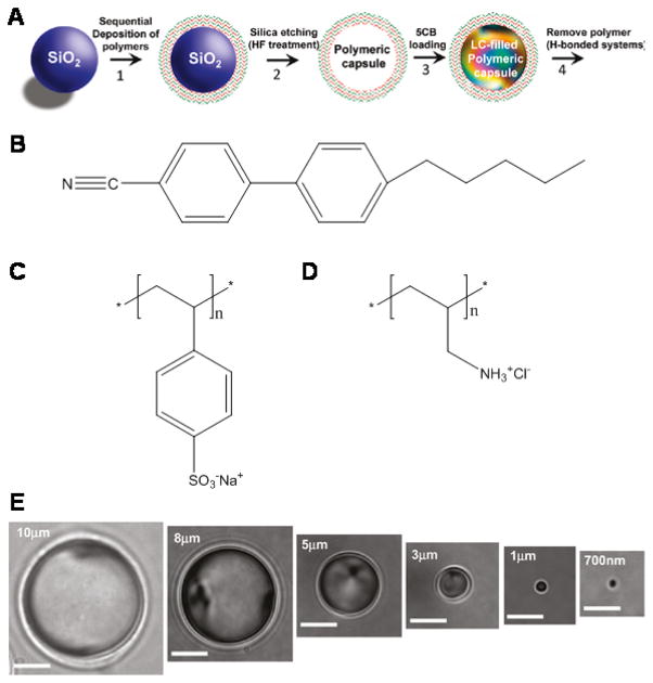
In addition to the phase separation processes described above in the context of PDLCs, methods that permit preparation of dispersions of LC droplets include sonication,14–16, 38,41, 42 microfluidics,43–45 homogenization,36 shearing of droplets and subsequent crystallization fractionation,41, 42 and dispersion polymerization.46–48 These methods, while generally effective for the preparation of LC droplets larger than 10 μm, do not work well at the 1 μm-scale. Recently, however, a new technique, which involves the templated synthesis of polyelectrolyte multilayer (PEM) capsules using sacrificial silica micro- or nano-particles and subsequent filling of the capsules with LC, has provided the necessary level of control to explore size-dependent ordering of LC droplets with sizes around 1 μm (Figure 3).37, 39
Figure 3.
(A) Procedure used to prepare LC droplets of predetermined sizes within polymeric multilayer capsules. Polymeric capsules were prepared by the sequential deposition of polyelectrolytes onto silica particles and the subsequent etching of silica. The resulting polymeric capsules were filled with LCs (see the text for details). (B–D) Chemical structures of the (B) 5CB and the polyelectrolytes used to create polymeric multilayer capsules ((C) PSS and (D) PAH). (E) Bright field micrographs of polymer-encapsulated 5CB droplets obtained using silica templates with diameters of 10 ± 0.22, 8 ± 0.20, 5 ± 0.19, 3 ± 0.18, 1 ± 0.04, and 0.7 ± 0.08 μm, respectively. All scale bars are 3 μm. Reproduced with permission.37
Here we briefly summarize the methodology. First, PEMs were formed on the surfaces of silica (template) particles of predetermined size via layer-by-layer adsorption of polyelectrolytes from aqueous solution. In the studies summarized below, the PEMs were prepared from the anionic polyelectrolyte poly(sodium 4-styrene-sulfonate) (PSS) and the cationic polyelectrolyte poly(allylamine hydrochloride) (PAH) (Figure 3C and D, respectively).37 Following formation of the PEMs, the silica template particles were selectively etched using hydrofluoric acid, resulting in formation of hollow PEM capsules. The hollow capsules were then infiltrated with an isotropic mixture of ethanol (5 wt%) and 4′-pentyl-4-cyanobiphenyl (5CB, Figure 3B). Finally, the ethanol was evaporated from the mixture, and the monodisperse nematic LC-filled PEM capsules were extracted into a bulk aqueous phase thus forming LC droplets of precise size that were encapsulated in PEMs of pre-determined chemical composition. Because a range of polymers can be incorporated into PEMs, this technique provides a level of control over both the interfacial chemistry of the LC droplets and the size of the LC droplets (as determined by the silica template particle; see Figure 3) that is difficult to achieve with other methods of preparing LC droplets. We end this section by noting that removal of the multilayers from the LC droplets to prepare “bare” droplets is possible using hydrogen bonded polymeric multilayers (e.g., poly-(methacrylic acid)/poly(vinylpyrrolidone)).13
Observation of Size-Dependent Ordering
Using the synthetic methodology described above, micrometer-sized droplets of nematic 5CB were prepared to study the size-dependent ordering in the droplets and thereby test prior theoretical predictions (see above).37 In the studies described below, the LC droplets were coated with PEMs prepared from PSS/PAH (Figure 3C and D). For encapsulated 5CB droplets with diameters larger than 3 μm, the LC was observed to exhibit a bipolar configuration (Figure 4C and D). This configuration is consistent with tangential anchoring of the LC on the PEM. Surprisingly, however, droplets with diameters of ~ 1 μm and 700 nm were observed to assume so-called preradial (Figure 4F–I) and radial (Figure 4K and L) configurations, respectively. In a radial configuration, the LC director is aligned normal to the droplet surface and a single point defect (or a very small disclination line in the shape of a ring)40, 49–51 is present at the core of each droplet (Figure 4M).10, 20, 37, 52 Similar to a radial configuration, the preradial configuration possesses a single point defect. However, this defect is located at the surface of the droplet rather than in the center of the droplet and the LC director is tilted at the droplet interface (Figure 4J).10, 15, 20, 52, 53 These results, obtained with the PEM-coated LC, thus revealed that polymer-coated LC droplets transition from a bipolar to the radial configuration (a so-called “bipolar-to-radial ordering transition”) with decreasing droplet size. Specifically, the LC droplets were not observed to transition to a homogeneous internal director configuration, as previously predicted on the basis of scaling arguments (see above).
The experimental results described above (and others that confirm the size-dependent ordering)14 have led to a reexamination of the relative importance of contributions to the LC droplet free energy, as described by equation 1. Specifically, by relaxing the one constant approximation4, 10 and including the contribution of the saddle-splay elastic constant (K24), it was shown that the above-described stabilization of the radial configuration relative to the uniform configuration could be predicted.37 In this revised treatment, the free energy of the radial configuration (Fr) is described as:54
| (5) |
where the first term is associated with splay deformation within the LC droplet, and the third term is the energetic penalty associated with a homeotropic orientation of the LC at the droplet interface (note that the easy axis is tangential to the droplet interface).37 The second term is associated with saddle-splay deformation of the LC, and favors the radial configuration.29, 37
In contrast to a radial configuration, a droplet with a uniform director profile is free of elastic strain. Thus, the only contribution to the free energy of a uniform LC droplet (Funiform) is an anchoring energy penalty: 37
| (6) |
By comparing equations 5 and 6, it is possible to predict that a radial configuration will be favored over a uniform director profile for droplets with R < 6K*/W, where K* = K24/2 − K11.37 While this analysis of the free energy can, in principle, provide an account for the stabilization of the radial configuration, it requires that K24 be greater than 2K11, which violates one of the Ericksen inequalities (K24 ≤ 2K11).55, 56 However, we note that more detail and quantitative numerical models have concluded that elastic constants that satisfy the Ericksen stability limits can predict stabilization of the radial configuration.57 We end by noting that experimental estimates of K24 vary widely and range up to 3.1K11.56 Thus, while it appears likely that K24 plays an important role in determining the configurations of the LC droplets, additional investigations are needed to provide a full account of the experimental observations.
We comment here that size-dependent bipolar-to-radial ordering transitions (similar to those reported above using PEM-coated LC droplets) have also been observed using bare LC droplets (free of polymer) in aqueous solutions at high ionic strength (~ 100 mM) and alkaline pH (> 12).14 Under these latter conditions, recently documented effects of electrical double layers58, 59 lead to sufficiently small anchoring energies that the size-dependent changes in configuration of the LCs are observed in the micrometer-range of sizes.
3. Ordering Transitions in LC Droplets Triggered Interactions with Biomolecular Species
Interactions between Lecithin and LC Droplets of PDLCs
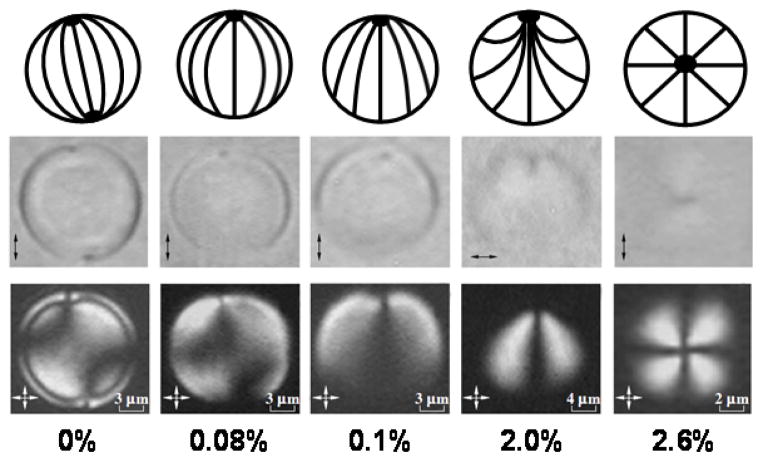
The observations of size-dependent ordering of LCs within droplets, as outlined in the first two sections of this perspective, have inspired and aided in the interpretation of a series of investigations of LC droplet systems that respond to the presence of biological species that assemble at the aqueous interface of the LC.6 Prior to discussing these investigations, here we mention briefly an early study that reported on the effects of incorporation of lecithin into the polymer matrix of a PDLC. Figure 5 shows a series of configurational states observed for 5CB droplets contained in a poly(vinyl butyral) matrix doped with increasing amounts of lecithin.20 Overall, these studies revealed configurations of the LC that corresponded to the bipolar, monopolar, preradial and radial states (each of which possess a single defect). In this study, however, the sizes of the LC droplets were not maintained constant (see scale bars in Figure 5). As described below, more recent studies with LC-in-water emulsions with LC droplets of well-defined size have revealed that the effects of adsorbates on LC configurations within droplets are size-dependent. In addition, observations of the dynamic transition pathways observed during the interaction of the adsorbate from the aqueous phase provide new insights into two distinct mechanisms by which adsorbates trigger LC ordering transitions (adsorption at the aqueous-LC interface or formation of self-assembled structures within LC droplets).
Figure 5.
Equilibrium director configurations observed in nematic LC droplets dispersed in a poly(vinyl butyral) matrix containing lecithin. The top row shows schematic illustrations of the configuration of the LC within each droplet, and the middle and bottom rows, respectively, show the corresponding bright field and polarized light micrographs of the 5CB droplets. The weight percent of lecithin doped into the polymeric matrix is indicated below each polarized light micrograph. Note that the scale-bar differs between figures. Double headed arrows in bright field micrographs indicate the orientation of the single polarizer, while double headed arrows in polarized light micrographs indicate the orientation of the crossed polarizers. Reproduced with permission.20
Adsorption of Amphiphiles at the Aqueous-LC Interface
The aqueous environment of LC-in-water emulsions provides a means of delivery of biomolecules to LC interfaces and also influences the interfacial adsorption process (e.g., through water mediated interactions such as those associated with hydrophobic hydration).5, 6, 8 As noted above, recent interest in aqueous dispersions of LCs has been motivated by prior reports that amphiphiles adsorb to and alter the orientational ordering of LCs at aqueous-LC interfaces.7, 60, 61 This phenomenon is commonly referred to as an “adsorbate-induced anchoring transition”13 and involves a change in the LC anchoring energy induced by the amphiphile (the second term in equation 1 for LC droplets). To change the anchoring energy to an extent that an ordering transition is triggered from the interface, a coverage of the interface by adsorbate of 0.1 to 1 Langmuir is typically required.20, 52, 61–63
Figure 6 shows an adsorbate-induced bipolar-to-radial ordering transition in water-dispersed droplets of nematic 5CB, where the adsorbate is sodium dodecyl sulfate (SDS).13 This figure demonstrates that an increasing concentration of adsorbate leads to a series of stable director configurations that are driven by changes in the anchoring of the LC at the droplet interface. The first transition shown in Figure 6 is a bipolar-to-axial transition, evidenced by the disappearance of the two point defects (boojums) at the diametric ends of the bipolar droplet and simultaneous appearance of a disclination ring near the droplet equator. With further increase in bulk surfactant concentration (and thus concentration of the SDS at the aqueous-LC interface), this ring defect moved towards a pole and shrank to a surface point defect, forming a preradial configuration. Finally, the point defect migrated from the surface of the droplet to the center, forming the radial structure. The above-described sequence of configurational states of the LC droplets observed with SDS is similar to that reported previously in a study of the effect of temperature on glycerol-dispersed 5CB droplets in the presence of a fixed concentration of lecithin.52 Whereas changes in temperature are expected to impact all terms in equation 1 (including elastic energies), the results reported recently with SDS clearly define the role of surface anchoring in dictating the series of configurational states shown in Figure 6. We comment that the sequence of configurational states observed in these two studies is distinct from that observed for polymer-dispersed 5CB droplets doped with lecithin (Figure 5). The reasons for these differences are not fully understood, but it is possible that they reflect differences in the uniformity of the distribution of adsorbates on the surfaces of the LC droplets.
Figure 6.
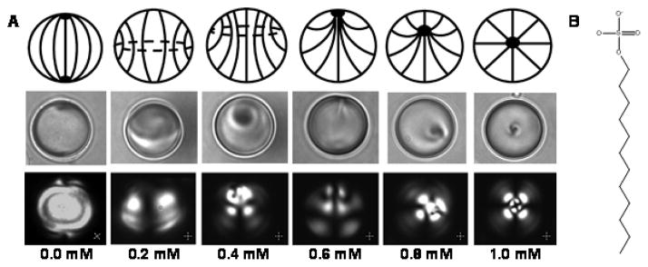
(A) Concentration-dependent equilibrium director configurations induced by an adsorbate-driven change in the anchoring energy of LC droplets coated by polymeric multilayer capsules composed of alternating layers of PSS and PAH (Figure 3C and D respectively). The change in surface anchoring of the LC droplet (from tangential to perpendicular) was achieved by equilibrating 8.0 ± 0.2-μm-diameter, polymer-encapsulated 5CB droplets with aqueous solutions containing SDS at concentrations that ranged from 0 to 1 mM (as indicated). The top row shows schematic illustrations of the configuration of the LC within each droplet, and the middle and bottom rows, respectively, show the corresponding bright field and polarized light micrographs of the 5CB droplets. (B) Molecular structure of sodium dodecyl sulfate (SDS). Reproduced with permission.13
Importantly, and as outlined in sections 1 and 2 of this perspective, the concentration of SDS that triggers the various internal configurations of LC droplets shown in Figure 6 can be tailored by taking advantage of the size-dependent energetics of the LC droplets. Specifically, Figure 7 shows one set of results obtained with LC droplets with diameters between 1 and 10μm.37 The observations of both a family of equilibrium director configurations as a function of interfacial concentration of adsorbate and the size-dependence of the responsiveness of LC droplets to adsorbates have initiated studies aimed at elucidation of general design principles for responsive materials based on LC droplets.6 Specifically, LC droplets have been shown to undergo ordering transitions in response to the presence of lipids,13, 16 surfactants,37, 64 proteins,13, 65–67 bile acids,68 and bacteria and viruses.63 Finally, we note that size-dependent ordering of LC droplets has also been exploited to design LC materials that respond to changes in ionic strength69 and pH45 of aqueous solutions and the presence of charged macromolecules.43
Figure 7.
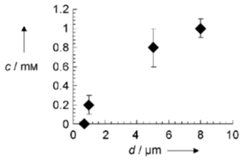
SDS concentrations (c) in aqueous solution that caused LC droplets of the indicated size (d) to assume a radial configuration. Reproduced with permission.37
Ordering Transitions Triggered by Self-Assembly of Amphiphiles within LC Droplets
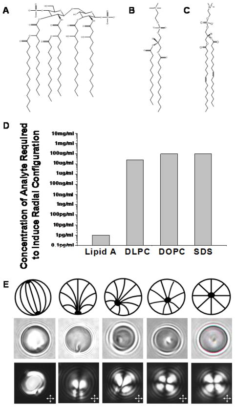
The configurational transitions described above rely on adsorbate-induced changes in the surface anchoring energy of LC droplets. Recent observations, however, also indicate that amphiphiles can associate with LC droplets to trigger ordering transitions through mechanisms that do not involve changes in anchoring energy of the LC. This new class of ordering transitions is, however, influenced by the size- dependent scaling of the interfacial and elastic contributions to the free energy of the LC droplets (as described above). Specifically, bipolar-to-radial ordering transitions have been observed in micrometer-sized droplets of nematic 5CB dispersed in aqueous solution in the presence of the bacterial lipopolysaccharide endotoxin (lipid A portion displayed in Figure 8A) at interfacial concentrations that are at least five orders of magnitude lower than the concentration required to saturate the surfaces of the droplets and cause ordering transitions through uniform changes in anchoring energies (Figure 8D).14, 16 We emphasize the remarkable nature of this configuration transition by noting that approximately 108 endotoxin molecules are needed to saturate the interface of a LC droplet with a diameter of 10 μm. In contrast, the configurational transition triggered by endotoxin involves, on average, roughly 103 endotoxin molecules for each LC droplet. In addition, the ordering transitions in the LC droplets were observed to occur through a kinetic pathway (series of transition states) that was distinct from that observed with adsorbates that induce changes in the anchoring energy of the LC droplets (compare Figure 8E to Figure 6), thus providing further support for the conclusion that the ordering transitions in the LC droplets caused by pg/mL concentrations of endotoxin are not driven by changes in anchoring energy.13, 20, 52 Finally, we comment that the sensitivity of the LC droplets to endotoxin was established to be a result of the lipid A component, as purified lipid A also triggered the configurational transitions at pg/mL concentrations.16
Figure 8.
Endotoxin-induced bipolar-to-radial ordering transitions in water-dispersed nematic 5CB droplets. (A–C) Molecular structure of (A) the glycolipid tail of endotoxin, lipid A, (B) 1,2-dilauroyl-sn-glycero-3-phosphatidylcholine (DLPC) and (C) 1,2-dioleoyl-sn-glycero-3-phosphatidylcholine (DOPC). (D) Bulk concentrations of lipids (endotoxin, DLPC, or DOPC) or surfactants (SDS, Figure 6B) in aqueous solution required to induce bipolar-to-radial ordering transitions in 5CB droplets. (E) Pathway of transition states observed during endotoxin-induced ordering transitions. The top row shows schematic illustrations of the configuration of the LC within each droplet, and the middle and bottom rows, respectively, show the corresponding bright field and polarized light micrographs of the 5CB droplets. The ordering transitions were triggered by exposure of 8-μm-diameter 5CB droplets to 10 pg/mL of endotoxin. Contrary to the pathway observed for adsorbate-induced ordering transitions (Figure 6), no disclination rings were observed during the transition of the droplets from bipolar to radial configurations in the presence of 10 pg/mL of endotoxin. Reproduced with permission.16
Subsequent experimental measurements have documented the important role of LC droplet size in the endotoxin-induced bipolar-to-radial configurational transition. For example, LC droplets with diameters larger than 10 μm were found to be insensitive to the presence of endotoxin at pg/mL concentrations, and remained in a bipolar configuration (Figure 9A).14 To provide insight into the origins of this unexpected sensitivity of LC droplets to endotoxin, a simple thermodynamic model was developed to estimate the influence of endotoxin on the free energy of LC droplets.14 Specifically, the free energy of a LC droplet in a bipolar configuration (Fbp) was approximated as:54
Figure 9.
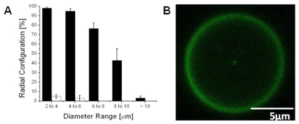
(A) Influence of LC droplet size on endotoxin-induced bipolar-to-radial ordering transitions in micrometer-sized droplets of nematic 5CB. The droplets were exposed to either an aqueous solution containing 100 pg/mL endotoxin (solid bar) or the same aqueous solution without endotoxin (open bar). No 5CB droplets were observed to exhibit a radial configuration in the absence of 100 pg/mL endotoxin above a diameter of 6 μm. (B) Confocal fluorescent micrograph showing localization of BODIPY-labeled endotoxin at the center of a 5CB droplet in the radial configuration. Reproduced with permission.14, 16
| (7) |
where K11 and K33 were assumed to be equal in magnitude. Combining equations 5 and 7, and adding a term that accounts for the relative influence of endotoxin on the free energies of bipolar and radial droplets (ΔFendotoxin), the change in free energy (associated with the interaction of endotoxin with the LC droplet) required to transform a LC droplet from a bipolar to a radial configuration (ΔFbp→r) was expressed as:14
| (8) |
By combining equation 8 with the experimental observation that endotoxin-induced ordering transitions in LC droplets were not observed for droplets with diameters greater than 10 μm (Figure 9A), and estimating K24 to be 1.53K11 (below the Ericksen limit of K24=2K11)55 and W to be 0.4 μJ/m2 (from experimental observations),14, 37 the interactions of endotoxin were estimated to influence the free energy of LC droplets (|ΔFendotoxin|) by ~10−17 J. Interestingly, this estimate for |ΔFendotoxin| is similar in magnitude to the standard free energy of the self-association of 103 endotoxin molecules, which is approximately the number of endotoxin molecules available per LC droplet in a solution of endotoxin at the pg/mL concentration level (see above).23, 24 Here we note that lipids with molecular architectures that are distinct from lipid A, namely double-tailed lipids such as DLPC and DOPC (Figure 8B and C, respectively), as well as SDS (Figure 6B), do not trigger configurational transitions in the pg/mL range (Figure 8D).16 These various observations, when combined, strongly suggest that endotoxin (or the lipid A component of endotoxin) is self-assembling within the LC droplets to trigger the ordering transitions. In contrast to DLPC, DOPC and SDS, lipid A possesses a molecular architecture that prefers self-assembly into “inverted” assemblies70, 71 (e.g., inverted hexagonal and cubic phases) suggesting that lipid A may prefer to assemble within the LC droplets. Indeed, initial evidence of the partitioning of endotoxin into the interior of LC droplets in the radial configuration has been obtained using confocal microscopy and fluorescently labeled endotoxin (Figure 9B). Detailed characterization of the organization of the endotoxin within the LC, however, remains to be accomplished.14, 16 We comment, however, that a roughly spherical assembly of endotoxin comprised of ~103 molecules would occupy a volume that has a diameter of a few tens of nanometers. We end by noting that a number of past studies have reported the partitioning of inclusions (e.g., colloidal particles to defects of LCs, see below, for recent examples). The free energy of the core of a point defect within a LC droplet is, however, estimated to be only 10−19 J. The “core displacement” mechanism invoked previously to describe the association of colloids with LC defects,72–75 therefore, appears to be a small part of the free energy change caused by the self-assembly of endotoxin within the LC droplets. Overall, these results highlight the many unresolved issues related to the interactions of amphiphiles with LC droplets, and they motivate ongoing investigations of the self-assembly of amphiphiles in LCs, particularly in the nanoscopic environments defined by defects in LCs.
4. Templated Synthesis of Polymer Particles with Chemical Patches Using LC Droplets
In addition to providing designs of stimuli-responsive soft materials, LC droplets have recently been explored as the basis of a general and facile class of templates for the synthesis of spherical and non-spherical polymer particles with chemical patches. The work was motivated by the observation that particles with either anisotropic shape or patterned surface chemistry are enabling new scientific and technological advances (e.g., intracellular delivery of particles;76 tuning of colloidal interactions between particles;77–81 stabilization of Pickering emulsions;82 manipulation of Brownian motion;83 and design of hierarchical structures using particles as building blocks84, 85). While non-spherical and chemically patterned particles represent an exciting frontier in materials science, the synthesis of such particles remains challenging.84–86 It is this challenge that has recently been addressed by particle synthesis templated using LC droplets.
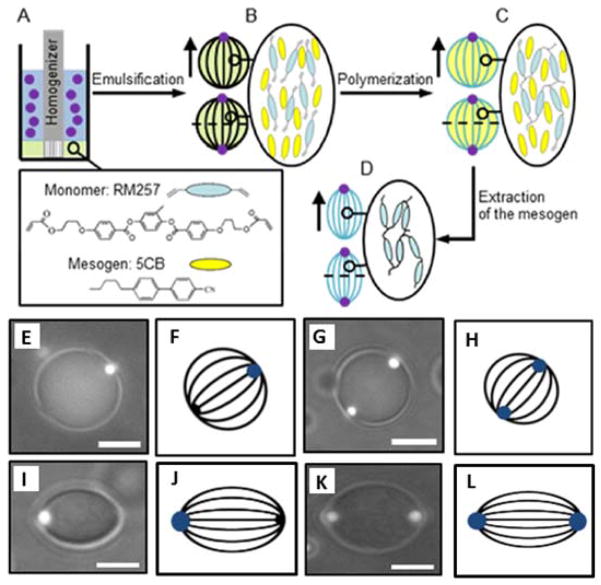
As noted above, a number of past studies have revealed that colloids can localize at defects in bulk LCs to decrease the free energy cost associated with both elastic deformations of LCs near defects and diminished orientational ordering of molecules in the core of the defects.87–90 Building from these prior observations, recent studies have used the defects associated with the bipolar configuration of LC droplets (the boojums) to localize the association of colloids with the LC droplets.10, 13, 17–20, 36 Figure 10 shows a schematic illustration of the synthetic scheme. First, 5CB-in-water emulsions were prepared by homogenizing 5CB in the presence of fluorescent polystyrene (PS) colloids (Figure 10A). After emulsification (Figure 10B), bipolar nematic droplets were obtained. Inspection of combined fluorescence and bright field micrographs (Figure 10E and G) revealed that the PS colloids adsorbed at the droplet surface and localized at the boojums of the bipolar droplets. Bipolar droplets possessing two boojums were used to direct the self-assembly of organic or inorganic colloids to the poles of droplets independent of the type of anchoring of the LC at the colloid surface.36
Figure 10.
(A–D) Synthesis of non-spherical and chemical-patterned particles. (A) Emulsification of LC. (B) After emulsification, formation of bipolar nematic droplets with either one or two fluorescent PS colloids located at the poles. (C) After polymerization of the monomer within the droplets, formation of spherical particles. (D) Upon the extraction of the LC from the polymerized droplets, formation of non-spherical particles. (E, G) Combined fluorescence and bright field micrographs of bipolar nematic droplets exhibiting one or two fluorescent PS colloids adsorbed at their surfaces. (I, K) Combined fluorescence and bright field, of non-spherical particles exhibiting one or two fluorescent PS particles. Scale bars: 5 μm. (F, H, J, L) The corresponding schematic illustrations of the director field configuration (dark lines) within spherical nematic droplets and non-spherical particles; the blue spots represent the PS colloids (at the poles). Reproduced with permission.36
While the scheme reported above leads to the formation of LC droplets with chemical patches at their poles (defined by the colloids), it was also demonstrated that photo-polymerization of reactive liquid crystalline mesogens could be performed to preserve the initial assembly (Figure 10C).91, 92
This procedure leads to spherical particles comprised of a cross-linked polymeric network that is swollen with 5CB. One or two poles of the particles were decorated with chemical patches defined by the colloids. Finally, it was also demonstrated that non-spherical particles could be obtained by extraction of LC from the above described particles (Figure 10D). Extraction of the 5CB resulted in contraction (de-swelling) of the polymerized particles in a direction perpendicular to the line joining the poles of the nematic droplets, as shown in Figure 10I–L. These observations indicated that the polymer network had been templated by the mesogens in the initial bipolar configuration of the nematic droplets. Overall, this study defines the basis of a general method for the synthesis of spherical and non-spherical particles possessing well-organized chemically distinct domains from LC-in-water emulsions. Ongoing efforts are aimed at using other configurations of LC droplets as templates for particle synthesis, including the size-dependent configurations of LC droplets described earlier in this perspective.
5. Conclusion and Future Directions
Much of the work described above is motivated by recent observations of size-dependent ordering of LCs within micrometer-sized droplets. Specifically, the observation that droplets of LC dispersed in aqueous solution, when prepared with decreasing size, exhibit a bipolar-to-radial transition in configuration, was not anticipated by previous theories of LC droplets.37 While it appears that the saddle-splay elastic constant of the LC plays a role in the size-dependent ordering, values of K24 that give rise to the experimentally observed size-dependent ordering lie close to or beyond the Eriksen limits for stability.55 This leaves open the possibility that the contribution of the elasticity of the LC to the free energy of the LC droplets is not correctly captured by existing theories or that other phenomena that influence the ordering of the LC are size-dependent. For example, recent studies have established that electrical double layers form on the LC-side of aqueous-LC interfaces.58, 59 It is possible, for example, that the contribution of the electrical double layer to the anchoring energy of the LC droplets is size-dependent. Additional studies, both experimental and theoretical, are needed to resolve these fundamental issues that influence the design of responsive soft materials based on LCs.
A second key issue that is highlighted by the results described above is related to the effects of specific lipids (e.g., lipid A of endotoxin) on the configurations of LC droplets. The remarkably low concentrations at which lipid A triggers changes in the configurations of LC droplets is inconsistent with a mechanism that involves changes in anchoring energy.14, 16 Specifically, we observe that the configurational transitions are triggered by ~103 lipid A molecules, whereas 108 molecules are required to increase the density of lipid A molecules at the interface of the LC droplets to a level that influences the orientation of the LC through a change in anchoring.14, 16 We emphasize that this effect is only observed for a range of LC droplet sizes for which elastic and interfacial contributions to the free energy are comparable in the radial and bipolar configurations. While aspects of the molecular mechanism of action of endotoxin remain to be fully elucidated, a number of experimental observations (and thermodynamic arguments) point to the formation of a self-assembled structure by the endotoxin within the core of radial LC droplets.16 This result (self-assembly in defects) thus goes beyond past studies that have explored the localization of preformed colloidal species at defects.87–90 This area is an exciting frontier of materials chemistry involving LCs that deserves additional investigation. Overall, the elucidation of molecular design principles for self-assembly in defects could lead to fundamentally new classes of LC-based materials with high responsiveness to molecular interactions.
Finally, we comment that LC droplets are emerging as a new class of templates for the synthesis of complex assemblies of colloidal species. The example presented in this perspective was focused on LC droplets with chemical patches,36 but the range of possibilities is very large as knowledge regarding defect structures formed in LC materials has progressed substantially over the past decade. For example, double emulsions, where a thin nematic shell separates two aqueous phases (so called “LC shells”) can be used to design new classes of soft materials with colloids precisely positioned via the use of defects.93–95,94, 96–99 Recently, the behavior of silica colloids and defects embedded in a nematic LC shell with tangential surface anchoring was investigated.100 The nematic LC shells potentially provide a way to generate colloidal-shell materials with new types of symmetries, valences and directionalities which may be exploited for controlled self-assembly of colloidal particles.
Acknowledgments
This work was primarily supported by NSF through DMR-1121288 (Materials Research Science and Engineering Center), the Army Research Office (W911NF-11-1-0251 andW911NF-10-1-0181), and the National Institutes of Health (AI092004 and CA108467). NLA thanks Frank Caruso and Juan de Pablo for collaborations that enabled aspects of the work reported in this perspective. The authors would like to thank Rebecca J. Carlton and Emre Bukusoglu for helpful discussions.
Biography
Nicholas L. Abbott is the John T. and Magdalen L. Sobota Professor of Chemical and Biological Engineering at University of Wisconsin-Madison, and the Director of the Wisconsin Materials Research Science and Engineering Center. He received his undergraduate education at University of Adelaide, Australia and a PhD from Massachusetts Institute of Technology. His research interests include design of stimuli-responsive surfactants, colloidal and interfacial phenomena involving liquid crystals, intermolecular forces in aqueous systems, and interfacial engineering of wound beds.
References
- 1.Chandrasekhar S. Liquid crystals. Cambridge University Press; Cambridge [England]; New York, NY, USA: 1992. [Google Scholar]
- 2.Collings PJ. Liquid crystals : nature’s delicate phase of matter. Princeton University Press; Princeton, N.J: 2002. [Google Scholar]
- 3.Collings PJ, Hird M. Introduction to liquid crystals chemistry and physics. Taylor & Francis; London; Bristol, PA: 1997. [Google Scholar]
- 4.Gennes P-Gd, Prost J. The physics of liquid crystals. Clarendon Press; Oxford University Press; Oxford New York: 1993. [Google Scholar]
- 5.Bai Y, Abbott NL. Langmuir. 2011;27:5719–5738. doi: 10.1021/la103301d. [DOI] [PMC free article] [PubMed] [Google Scholar]
- 6.Carlton RJ, Hunter JT, Miller DS, Abbasi R, Mushenheim PC, Tan L, Abbott NL. Liquid Crystal Reviews. 2013;1:1–23. doi: 10.1080/21680396.2013.769310. [DOI] [PMC free article] [PubMed] [Google Scholar]
- 7.Lockwood NA, Gupta JK, Abbott NL. Surface Science Reports. 2008;63:255–293. [Google Scholar]
- 8.Lowe AM, Abbott NL. Chemistry of Materials. 2012;24:746–758. doi: 10.1021/cm202632m. [DOI] [PMC free article] [PubMed] [Google Scholar]
- 9.Craighead H, Cheng J, Hackwood S. Applied Physics Letters. 1982;40:22–24. [Google Scholar]
- 10.Drzaic PS. Liquid Crystal Dispersions. World Scientific; Singapore; River Edge, NJ: 1995. [Google Scholar]
- 11.Fergason JL. Polymer encapsulated nematic liquid crystals for display and light control applications. SID Int Symp Dig. 1985 [Google Scholar]
- 12.Drzaic P. Molecular Crystals and Liquid Crystals. 1988;154:289–306. [Google Scholar]
- 13.Gupta JK, Zimmerman JS, de Pablo JJ, Caruso F, Abbott NL. Langmuir. 2009;25:9016–9024. doi: 10.1021/la900786b. [DOI] [PubMed] [Google Scholar]
- 14.Miller DS, Abbott NL. Soft Matter. 2013;9:374–382. doi: 10.1039/C2SM26811F. [DOI] [PMC free article] [PubMed] [Google Scholar]
- 15.Miller DS, Carlton RJ, Mushenheim PC, Abbott NL. Langmuir. 2013;29:3154–3169. doi: 10.1021/la304679f. [DOI] [PMC free article] [PubMed] [Google Scholar]
- 16.Lin IH, Miller DS, Bertics PJ, Murphy CJ, de Pablo JJ, Abbott NL. Science. 2011;332:1297–1300. doi: 10.1126/science.1195639. [DOI] [PMC free article] [PubMed] [Google Scholar]
- 17.Berggren E, Zannoni C, Chiccoli C, Pasini P, Semeria F. Physical Review E. 1994;50:2929–2939. doi: 10.1103/physreve.50.2929. [DOI] [PubMed] [Google Scholar]
- 18.Meyer RB. Physical Review Letters. 1969;22:918–921. [Google Scholar]
- 19.Ondris-Crawford R, Boyko EP, Wagner BG, Erdmann JH, Zumer S, Doane JW. Journal of Applied Physics. 1991;69:6380–6386. [Google Scholar]
- 20.Prischepa OO, Shabanov AV, Zyryanov VY. Jetp Letters. 2004;79:257–261. [Google Scholar]
- 21.Rapini A, Papoular M. J Phys Colloques. 1969;30:C4-54–C4-56. [Google Scholar]
- 22.Lavrentovich OD. Liquid Crystals. 1998;24:117–125. [Google Scholar]
- 23.Hiemenz PC, Rajagopalan R. Principles of colloid and surface chemistry. Marcel Dekker; New York: 1997. [Google Scholar]
- 24.Israelachvili JN. Intermolecular and surface forces. Academic Press London; London; San Diego: 1991. [Google Scholar]
- 25.Kléman M, Lavrentovich OD. Soft matter physics : an introduction. Springer; New York: 2003. [Google Scholar]
- 26.Napoli G, Vergori L. Physical Review Letters. 2012;108:207803-1–207803-5. doi: 10.1103/PhysRevLett.108.207803. [DOI] [PubMed] [Google Scholar]
- 27.Prinsen P, van der Schoot P. Physical Review E. 2003;68:021701-1–021701-11. doi: 10.1103/PhysRevE.68.021701. [DOI] [PubMed] [Google Scholar]
- 28.Frank FC. Discussions of the Faraday Society. 1958;25:19–28. [Google Scholar]
- 29.Zumer S, Kralj S. Liquid Crystals. 1992;12:613–624. [Google Scholar]
- 30.Allender DW, Crawford GP, Doane JW. Physical Review Letters. 1991;67:1442–1445. doi: 10.1103/PhysRevLett.67.1442. [DOI] [PubMed] [Google Scholar]
- 31.Goyal RK, Denn MM. Physical Review E. 2007;75:021704-1–021704-10. doi: 10.1103/PhysRevE.75.021704. [DOI] [PubMed] [Google Scholar]
- 32.Erdmann JH, Zumer S, Doane JW. Physical Review Letters. 1990;64:1907–1910. doi: 10.1103/PhysRevLett.64.1907. [DOI] [PubMed] [Google Scholar]
- 33.Kralj S, Zumer S. Physical Review A. 1992;45:2461–2470. doi: 10.1103/physreva.45.2461. [DOI] [PubMed] [Google Scholar]
- 34.Ruhwandl RW, Terentjev EM. Physical Review E. 1997;56:5561–5565. [Google Scholar]
- 35.Zhang ZX, van Duijneveldt JS. Soft Matter. 2007;3:596–604. doi: 10.1039/b613327d. [DOI] [PubMed] [Google Scholar]
- 36.Mondiot F, Wang X, de Pablo JJ, Abbott NL. Journal of the American Chemical Society. 2013;135:9972–9975. doi: 10.1021/ja4022182. [DOI] [PMC free article] [PubMed] [Google Scholar]
- 37.Gupta JK, Sivakumar S, Caruso F, Abbott NL. Angewandte Chemie-International Edition. 2009;48:1652–1655. doi: 10.1002/anie.200804500. [DOI] [PubMed] [Google Scholar]
- 38.Tixier T, Heppenstall-Butler M, Terentjev EM. Langmuir. 2006;22:2365–2370. doi: 10.1021/la0531953. [DOI] [PubMed] [Google Scholar]
- 39.Sivakumar S, Gupta JK, Abbott NL, Caruso F. Chemistry of Materials. 2008;20:2063–2065. [Google Scholar]
- 40.Bodnar VG, Lavrentovich OD, Pergamenshchik VM. Zhurnal Eksperimentalnoi I Teoreticheskoi Fiziki. 1992;101:111–125. [Google Scholar]
- 41.Bibette J. Journal of Colloid and Interface Science. 1991;147:474–478. [Google Scholar]
- 42.Hsu P, Poulin P, Weitz DA. Journal of Colloid and Interface Science. 1998;200:182–184. [Google Scholar]
- 43.Bera T, Fang JY. Journal of Materials Chemistry. 2012;22:6807–6812. [Google Scholar]
- 44.Fernandez-Nieves A, Cristobal G, Garces-Chavez V, Spalding GC, Dholakia K, Weitz DA. Advanced Materials. 2005;17:680–684. [Google Scholar]
- 45.Khan W, Choi JH, Kim GM, Park SY. Lab on a Chip. 2011;11:3493–3498. doi: 10.1039/c1lc20402e. [DOI] [PubMed] [Google Scholar]
- 46.Sandomirski K, Martin S, Maret G, Stark H, Gisler T. Journal of Physics-Condensed Matter. 2004;16:S4137–S4144. [Google Scholar]
- 47.Vennes M, Martin S, Gisler T, Zentel R. Macromolecules. 2006;39:8326–8333. [Google Scholar]
- 48.Vennes M, Zentel R. Macromolecular Chemistry and Physics. 2004;205:2303–2311. [Google Scholar]
- 49.Gartland EC, Mkaddem S. Physical Review E. 1999;59:563–567. [Google Scholar]
- 50.Mkaddem S, Gartland EC. Physical Review E. 2000;62:6694–6705. doi: 10.1103/physreve.62.6694. [DOI] [PubMed] [Google Scholar]
- 51.Lavrentovich OD, Terentiev EM. Zhurnal Eksperimentalnoi I Teoreticheskoi Fiziki. 1986;91:2084–2096. [Google Scholar]
- 52.Volovik GE, Lavrentovich OD. Zhurnal Eksperimentalnoi I Teoreticheskoi Fiziki. 1983;85:1997–2010. [Google Scholar]
- 53.Prishchepa OO, Zyryanov VY, Gardymova AP, Shabanov VF. Molecular Crystals and Liquid Crystals. 2008;489:84–93. [Google Scholar]
- 54.Dubois-Violette E, Parodi E. J Phys (Paris) Colloq. 1969;30:57–64. [Google Scholar]
- 55.Ericksen JL. Physics of Fluids. 1966;9:1205–1207. [Google Scholar]
- 56.Polak RD, Crawford GP, Kostival BC, Doane JW, Zumer S. Physical Review E. 1994;49:R978–R981. doi: 10.1103/physreve.49.r978. [DOI] [PubMed] [Google Scholar]
- 57.Tomar V, Hernandez SI, Abbott NL, Hernandez-Ortiz JP, de Pablo JJ. Soft Matter. 2012;8:8679–8689. [Google Scholar]
- 58.Carlton RJ, Gupta JK, Swift CL, Abbott NL. Langmuir. 2012;28:31–36. doi: 10.1021/la203729t. [DOI] [PMC free article] [PubMed] [Google Scholar]
- 59.Carlton RJ, Ma CD, Gupta JK, Abbott NL. Langmuir. 2012;28:12796–12805. doi: 10.1021/la3024293. [DOI] [PMC free article] [PubMed] [Google Scholar]
- 60.Brake JM, Daschner MK, Abbott NL. Langmuir. 2005;21:2218–2228. doi: 10.1021/la0482397. [DOI] [PubMed] [Google Scholar]
- 61.Brake JM, Daschner MK, Luk YY, Abbott NL. Science. 2003;302:2094–2097. doi: 10.1126/science.1091749. [DOI] [PubMed] [Google Scholar]
- 62.Meli MV, Lin IH, Abbott NL. Journal of the American Chemical Society. 2008;130:4326–4333. doi: 10.1021/ja077379a. [DOI] [PubMed] [Google Scholar]
- 63.Sivakumar S, Wark KL, Gupta JK, Abbott NL, Caruso F. Advanced Functional Materials. 2009;19:2260–2265. [Google Scholar]
- 64.Tjipto E, Cadwell KD, Quinn JF, Johnston APR, Abbott NL, Caruso F. Nano Letters. 2006;6:2243–2248. doi: 10.1021/nl061604p. [DOI] [PubMed] [Google Scholar]
- 65.Alino VJ, Pang J, Yang KL. Langmuir. 2011;27:11784–11789. doi: 10.1021/la2022215. [DOI] [PubMed] [Google Scholar]
- 66.Alino VJ, Sim PH, Choy WT, Fraser A, Yang KL. Langmuir. 2012;28:17571–17577. doi: 10.1021/la303213h. [DOI] [PubMed] [Google Scholar]
- 67.Alino VJ, Tay KX, Khan SA, Yang KL. Langmuir. 2012;28:14540–14546. doi: 10.1021/la3028463. [DOI] [PubMed] [Google Scholar]
- 68.Bera T, Fang JY. Langmuir. 2013;29:387–392. doi: 10.1021/la303771t. [DOI] [PubMed] [Google Scholar]
- 69.Zou JH, Bera T, Davis AA, Liang WL, Fang JY. Journal of Physical Chemistry B. 2011;115:8970–8974. doi: 10.1021/jp201909m. [DOI] [PubMed] [Google Scholar]
- 70.Brandenburg K, Koch MHJ, Seydel U. Journal of Structural Biology. 1992;108:93–106. doi: 10.1016/1047-8477(92)90010-8. [DOI] [PubMed] [Google Scholar]
- 71.Seydel U, Schromm AB, Blunck R, Brandenburg K. Cd14 in the Inflammatory Response. 2000;74:5–24. doi: 10.1159/000058754. [DOI] [PubMed] [Google Scholar]
- 72.Coles HJ, Pivnenko MN. Nature. 2005;436:997–1000. doi: 10.1038/nature03932. [DOI] [PubMed] [Google Scholar]
- 73.Kikuchi H, Yokota M, Hisakado Y, Yang H, Kajiyama T. Nature Materials. 2002;1:64–68. doi: 10.1038/nmat712. [DOI] [PubMed] [Google Scholar]
- 74.Nakata M, Takanishi Y, Watanabe J, Takezoe H. Physical Review E. 2003;68:041710-1–041710-6. doi: 10.1103/PhysRevE.68.041710. [DOI] [PubMed] [Google Scholar]
- 75.Rozic B, Tzitzios V, Karatairi E, Tkalec U, Nounesis G, Kutnjak Z, Cordoyiannis G, Rosso R, Virga EG, Musevic I, Kralj S. European Physical Journal E. 2011;34:1–11. doi: 10.1140/epje/i2011-11017-8. [DOI] [PubMed] [Google Scholar]
- 76.Muro S, Garnacho C, Champion JA, Leferovich J, Gajewski C, Schuchman EH, Mitragotri S, Muzykantov VR. Molecular Therapy. 2008;16:1450–1458. doi: 10.1038/mt.2008.127. [DOI] [PMC free article] [PubMed] [Google Scholar]
- 77.Botto L, Lewandowski EP, Cavallaro M, Stebe KJ. Soft Matter. 2012;8:9957–9971. [Google Scholar]
- 78.Lapointe CP, Mason TG, Smalyukh II. Science. 2009;326:1083–1086. doi: 10.1126/science.1176587. [DOI] [PubMed] [Google Scholar]
- 79.Loudet JC, Alsayed AM, Zhang J, Yodh AG. Physical review letters. 2005;94:018301-1–018301-4. doi: 10.1103/PhysRevLett.94.018301. [DOI] [PubMed] [Google Scholar]
- 80.Mondiot F, Chandran SP, Mondain-Monval O, Loudet JC. Physical Review Letters. 2009;103:238303-1–238303-4. doi: 10.1103/PhysRevLett.103.238303. [DOI] [PubMed] [Google Scholar]
- 81.Yao L, Botto L, Cavallaro M, Bleier BJ, Garbin V, Stebe KJ. Soft Matter. 2013;9:779–786. [Google Scholar]
- 82.Madivala B, Vandebril S, Fransaer J, Vermant J. Soft Matter. 2009;5:1717–1727. [Google Scholar]
- 83.Han Y, Alsayed AM, Nobili M, Zhang J, Lubensky TC, Yodh AG. Science. 2006;314:626–630. doi: 10.1126/science.1130146. [DOI] [PubMed] [Google Scholar]
- 84.Costi R, Saunders AE, Banin U. Angewandte Chemie-International Edition. 2010;49:4878–4897. doi: 10.1002/anie.200906010. [DOI] [PubMed] [Google Scholar]
- 85.Glotzer SC, Solomon MJ. Nature Materials. 2007;6:557–562. doi: 10.1038/nmat1949. [DOI] [PubMed] [Google Scholar]
- 86.Duguet E, Desert A, Perro A, Ravaine S. Chemical Society Reviews. 2011;40:941–960. doi: 10.1039/c0cs00048e. [DOI] [PubMed] [Google Scholar]
- 87.Fleury JB, Pires D, Galerne Y. Physical Review Letters. 2009;103:267801-1–267801-4. doi: 10.1103/PhysRevLett.103.267801. [DOI] [PubMed] [Google Scholar]
- 88.Pires D, Fleury JB, Galerne Y. Physical Review Letters. 2007;98:247801-1–247801-4. doi: 10.1103/PhysRevLett.98.247801. [DOI] [PubMed] [Google Scholar]
- 89.Ravnik M, Alexander GP, Yeomans JM, Zumer S. Faraday Discussions. 2010;144:159–169. doi: 10.1039/b908676e. [DOI] [PubMed] [Google Scholar]
- 90.Skarabot M, Ravnik M, Zumer S, Tkalec U, Poberaj I, Babic D, Musevic I. Physical Review E. 2008;77:061706-1–061706-4. doi: 10.1103/PhysRevE.77.061706. [DOI] [PubMed] [Google Scholar]
- 91.Crawford GP, Polak RD, Scharkowski A, Chien LC, Doane JW, Zumer S. Journal of Applied Physics. 1994;75:1968–1971. [Google Scholar]
- 92.Fernandez-Nieves A. Soft Matter. 2006;2:105–108. doi: 10.1039/b512441g. [DOI] [PubMed] [Google Scholar]
- 93.Arsenault A, Fournier-Bidoz SB, Hatton B, Miguez H, Tetrault N, Vekris E, Wong S, Yang SM, Kitaev V, Ozin GA. Journal of Materials Chemistry. 2004;14:781–794. [Google Scholar]
- 94.Nelson DR. Nano Letters. 2002;2:1125–1129. [Google Scholar]
- 95.Poon W. Science. 2004;304:830–831. doi: 10.1126/science.1097964. [DOI] [PubMed] [Google Scholar]
- 96.Bates MA, Skacej G, Zannoni C. Soft Matter. 2010;6:655–663. [Google Scholar]
- 97.Lopez-Leon T, Koning V, Devaiah KBS, Vitelli V, Fernandez-Nieves A. Nature Physics. 2011;7:391–394. [Google Scholar]
- 98.Lubensky TC, Prost J. Journal De Physique Ii. 1992;2:371–382. [Google Scholar]
- 99.Skacej G, Zannoni C. Physical Review Letters. 2008;100:197802-1–197802-4. doi: 10.1103/PhysRevLett.100.197802. [DOI] [PubMed] [Google Scholar]
- 100.Gharbi MA, Seč D, Lopez-Leon T, Nobili M, Ravnik M, Žumer S, Blanc C. Soft Matter. 2013;9:6911–6920. [Google Scholar]


