Abstract
Microgel particles capable of bulk-degradation have been synthesized from a solution of diacrylated triblock copolymer composed of poly(ethylene glycol) (PEG) and poly(lactic acid) (PLA) in a microfluidic device using stop flow lithography (SFL). It has been previously demonstrated that SFL can be used to fabricate particles with precise control over particle size and shape. Here we have fabricated hydrogel particles of varying size and shape and examined their mass-loss and swelling behavior histologically and mechanically. We report that these features in addition to the degradation behavior of the hydrogel particles may be tailored with SFL. By decreasing the applied UV dose during fabrication, hydrogel particles can be made to exhibit a distinct deviation from the classical erosion profiles of bulk-degrading hydrogels. At higher UV doses, a saturation in cross-linking density occurs and bulk-degrading behavior is observed. Finally, we synthesized multifunctional composite particles, providing unique features not found in homogeneous hydrogels.
Introduction
The development of degradable hydrogel materials has progressed rapidly in the past decade due to an acute interest in their functionality as drug delivery vehicles1,2 and tissue engineering scaffolds3. The synthesis and bulk characterization of a copious number of surface and bulk eroding hydrogels has been reported. Surface degrading hydrogels are, in general, excellent candidates for time dependent release of therapeutic agents while bulk degrading hydrogels are highly valued as cell encapsulants, which can be uniformly remodeled into native extracellular tissue matrix. For tissue engineering applications specifically, surface degrading materials erode over long time scales, but do not optimally sustain extracellular matrix production during erosion. Bulk eroding materials may be designed to erode quickly, but prematurely lose their mechanical integrity shortly after the hydrogel mesh size becomes ideal for tissue process elaboration.
While the erosion profile of a bulk hydrogel may be readily tuned by tailoring the chemical properties of its constitutive polymer, it may not be easily fabricated, patterned or modified on the scale of single cells. There is, therefore, significant interest in fabricating microstructures and microparticles from hydrogel materials for molecular therapeutics delivery4, candidate scaffold material screening and cell patterning5,6. Microfluidic-based microfabrication has proven to be an effective technology to generate microgel particles. For instance, hydrogel microstructures have been patterned upon surfaces within microchannels and subsequently removed to produce free particles7. Hydrogel microparticles have also been fabricated in a much higher throughput fashion using multiphase microfluidic emulsification8,9 in conjunction with photopolymerizable or chemically or thermally gelled polymers. This technique excels at rapidly producing large quantities of monodisperse particles. Additionally, the shape of these particles may be affected with the dimensions of the microchannel in which the solution is polymerized10,11. Microfluidic emulsification has been used to create particles composed of agarose12, alginate13, photocurable organic adhesives10, acrylamides14, and a variety of acrylated15 and methacrylated16 water soluble polymers.
A more versatile single-phase microfluidic technique, known as stop flow lithography (SFL) has been developed17,18 that allows for the direct fabrication of homogeneous microgel particles of custom shape and variable composition. SFL relies upon the projection of a photomask upon a focal plane within a microfluidic channel that is filled with a photopolymerizable polymer solution. SFL has been previously used to produce multifunctional hydrogel particles19, oxide and non-oxide microstructures20, cell encapsulating particles21 and Janus granules18.
We present here an extension of SFL to the production of microscale hydrogel particles from a bulk degradable polymer with arbitrary shapes and compositions and tunable time-dependent properties. We fabricate microgel particles from a solution of diacrylated triblock copolymer composed of poly(ethylene glycol) (PEG) and poly(lactic acid) (PLA) that has been extensively characterized as a degradable tissue scaffold for chondrocytes22,23, osteoblasts24 and human mesenchymal stem cells25-27, among others. Diacrylate PLA-b-PEG-b-PLA is a highly crosslinked, water swollen gel network that degrades through the isotropic hydrolysis of ester bonds in the PLA block28. As degradation proceeds, water content of the gel increases exponentially until complete dissolution of the network is reached29. Over this time period the gel volume increases while the static compressive modulus of the gel decreases in proportion to the extent of network degradation30. To compare our microgel particles to extensively studied, conventionally polymerized macroscale gels, we directly measure the particle size by optical histology and the particle elastic modulus by atomic force microscopy-enabled nanoindentation. Our analysis reveals that, while the degradation mechanism is identical, the erosion profiles for SFL-produced microgels are strongly dependent upon particle fabrication conditions and can be carefully tuned to provide variable time-dependent network erosion.
We hypothesize that this behavior arises as a result of oxygen gradients within the polymer solution in the microchannel. Oxygen inhibits the polymerization reaction and thus these gradients give rise to particles with non-uniform network crosslinking density in the axis of optical illumination and near the particle edges. This feature enables the fabrication by SFL of bulk-degradable microgel particles that erode with heterogeneous profiles that are not accessible through photopolymerization of a macroscale hydrogel construct. To support this hypothesis and extend the control that one has over particle morphology and intraparticle cross-linking density profile, we incorporate grayscale lithography into SFL to produce multifunctional particles with lateral variations in cross-linking density. Grayscale lithography has been previously discussed for single step fabrication of graded-height microfluidic channel networks31, MEMS32 and other planar features33, but has not been used in the fabrication of microgels. Gradient generators34 have been previously employed as a means of producing hydrogels with cross-linking density gradients35, but are limited to simple gradients and have not been applied to the fabrication of mobile phase particles. Here, we show that through mask selection, optical exposure intensity and polymer composition, degradable particles may be fabricated with customizable control over morphology, composition and erosion profile. Finally, we demonstrate the release of small particles from microgel constructs with spatially-varying erosion profiles.
Results and Discussion
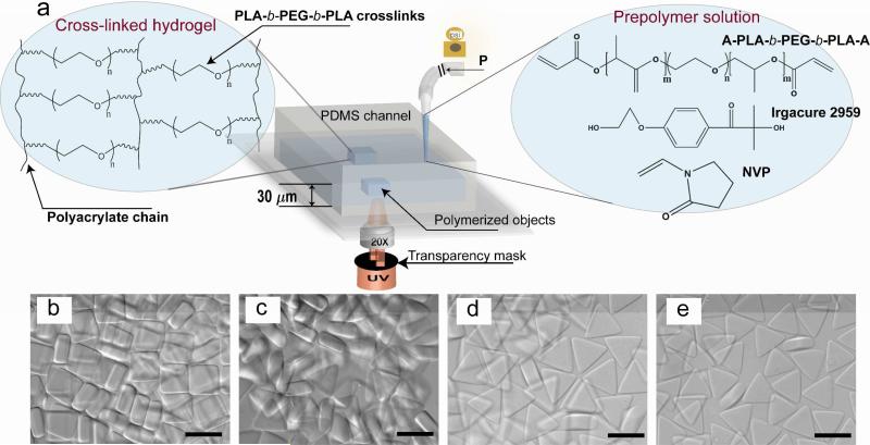
Hydrogel microparticles were fabricated using stop flow lithography that has been described previously18. The basis of this technique as well as the degradable PEG hydrogel chemistry is depicted schematically in Figure 1a. Photocurable prepolymer solutions are pumped through a thin microfluidic channel into which a UV light beam is projected through a photomask. Applied pneumatic pressure is employed to pump the prepolymer solution through the microchannel; removal of the pressure quickly arrests the viscous flow, allowing polymerization to be performed in a quiescent media. In the UV projection region, photoinitiated conversion of acrylate endgroups into polyacrylate forms the backbone of a 3D hydrogel network crosslinked by PEG-PLA chains. The shape of the hydrogel particles in the plane of the UV projection area is determined by the pattern of the transparency mask. Oxygen inhibition near PDMS microchannel surfaces produces unpolymerized layers at both top and bottom surfaces, preventing polymerization across the span and enabling the particles to be flushed out of the channel without sticking 36. The resulting hydrogel particles are shown in Figure 1b-e. Square hydrogel particles are composed of 30 wt% PEGDA as a control and equilateral triangles using three different concentrations of diacrylate PLA-b-PEG-b-PLA macromers (30, 20, and 10 wt %). These particles were used to investigate the erosion behavior of microhydrogels.
Figure 1.
(a) Schematic depicting non-spherical microhydrogel synthesis using stop-flow lithography, chemical structure of the biodegradable diacrylate PLA-b-PEG-b-PLA macromer, photoinitator, and accelerator (right), and idealized diacrylate PLA-b-PEG-b-PLA hydrogel network after photopolymerization (left). Particles are formed through three steps: (i) a prepolymer solution (diacrylate PLA-b-PEG-b-PLA or PEGDA with Irgacure 2959 and NVP) is flowed through a PDMS channel by a regulated pressure, (ii) the flow is stopped and particles are polymerized with a desired pulse of UV exposed through a photomask and microscope objective, (iii) the polymerized particles are flushed out of the channel and collected. (b-e) Optical images of the resulting hydrogels: (b) non-degradable hydrogels (rectangules, PEGDA 30 wt %) as the control and (c-e) degradable hydrogels (triangles, (c) diacrylate PLA-b-PEG-b-PLA 30 wt %, (d) 20 wt %, and (e) 10 wt %). Their thicknesses are ~ 26 μm (rectangles, control) and ~25, 22, and 17 μm (triangles, c, d, e respectively) Scale bars are all 50 μm. An exposure dose of 0.044 J/cm2 UV is used for all hydrogel particles shown here.
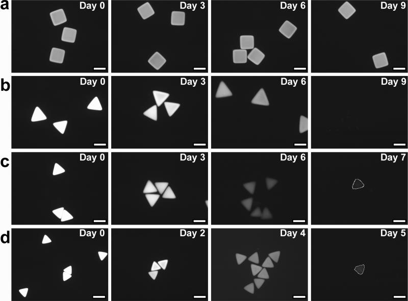
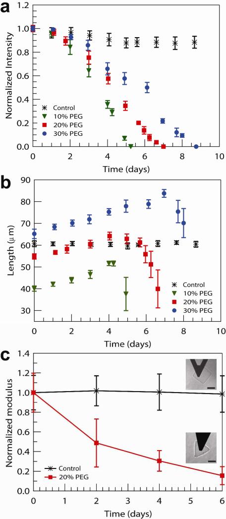
Degradation of the diacrylate PLA-b-PEG-b-PLA copolymer hydrogels used in this study arises from the cleavage of hydrolytically labile ester linkages (see Figure 1a) in PLA28,37, breaking cross-links within the gel. The products of degradation, poly(acrylic acid), PEG and lactic acid, are removed from the network by diffusive transport. Thus, the direct incorporation of a fluorescent label into the three-dimensional hydrogel network by polymerization allows changes in a particle's fluorescent intensity to be observed histologically and correlated with particle's mass loss. Furthermore, this allows for visual observation of erosion behavior of the resulting hydrogel particles. Therefore, Rhodamine B was introduced as a fluorescent label into the hydrogel structure, shown in Figure 1b-e. As expected, Figures 2a shows that non-degradable control particles (rectangles) display no change in size or fluorescent intensity from initial equilibrium measurements (Day 0) throughout the entire observation period of 9 days. Degradable diacrylate PLA-b-PEG-b-PLA-based hydrogels (triangles) meanwhile demonstrated histologically measurable changes in size and fluorescent intensity (Figure 2b-d). The fluorescence intensity from degradable particles gradually but steadily decreased over time, eventually disappearing altogether as the hydrogel fluidized. In the first days of degradation, the observed size increases as particle shape is roughly conserved. Erosion of the cross-linked network in turn amplifies hydrogel swelling and increases network mesh size as retractile forces are diminished28,37,38. Unexpectedly, these biodegradable hydrogels synthesized by SFL display degradation profiles that deviate sharply from thoroughly documented macroscale bulk degradable diacrylate PLA-b-PEG-b-PLA-based hydrogels28. As shown in Figure 3 the size of SFL-fabricated microgel particles initially increases, as anticipated as a more highly swollen state is achieved. In advanced stages of degradation, however, the particle size decreases steadily instead of swelling to infinite volume, as one would expect.
Figure 2.
Development of fluorescent intensities of non- and degradable hydrogel particles during the incubation in a PBS buffer (7.2 pH) at 37°C: (a) the control (PEGDA 30 wt %), (b) diacrylate PLA-b-PEG-b-PLA 30 wt %, (c) 20 wt %, and (d) 10 wt % corresponding to the hydrogels shown in Figure 1b-e, respectively. Scale bars are all 50μm. On Day 7 (c) and Day 5 (d), lines drawn indicate a trace of the hydrogels to as a guide to the eye.
Figure 3.
(a) Fluorescence intensity, normalized by intensity at Day 0 for each sample, and (b) growth of the side length of non-degradable (control, rectangles PEGDA 30 wt %) and degradable (triangles, diacrylate PLA-b-PEG-b-PLA 30 wt %, 20 wt %, and 10 wt %) hydrogel particles. (c) Elastic modulus E, normalized by E at Day 0 for each sample, for non- (control, rectangles, PEGDA 30 wt %) and degradable hydrogels (triangles, diacrylate PLA-b-PEG-b-PLA 20 wt %) using AFM-enabled nanoindentation. The Elastic mduli are E = 11.0 +/- 4 kPa for the rectangles and from E = 7.5 +/- 1.5 kPa (Day 0) to E = 1.2 +/- 0.7 kPa (Day 6) for the triangles. The hydrogel particles correspond to those shown in Figure 1(b-e).
These distinct erosion profiles can be seen in Figure 3a and b. A decline of measured fluorescent intensity is observed for particles of all initial diacrylate PLA-b-PEG-b-PLA concentrations (Figure 3a). Mass loss is markedly different from the behavior commonly reported for typical bulk degradable hydrogels, which normally exhibit a sharp decrease in the mass loss immediately prior to gel dissolution (i.e., the last 20% of mass loss28). The swelling behavior of degradable microgel particles is also qualitatively different from macroscale hydrogels (Figure 3b). The increase in side length reaches a maximum and subsequently decreases, which is quite different from bulk hydrogels, which display exponential growth in their equilibrium swollen volume over time28. We also measured the elastic moduli E of individual hydrogel particles via atomic force microscopy (AFM)-enabled indentation (Figure 3c). As expected of PEG-based hydrogels, E of control particles (PEGDA 30wt%) was in the kPa-range (E = 11.0 +/- 4 kPa) and did not decrease significantly with time (P<0.05) over 6 days immersed in PBS. In contrast, E of diacrylate PLA-b-PEG-b-PLA 20wt% particles decreased by 84%, from E = 7.5 +/- 1.5 kPa (Day 0) to E = 1.2 +/- 0.7 kPa (Day 6). Beyond Day 6, the stiffness of these degrading hydrogel particles was statistically lower than that of the control particles (P<0.001) throughout the degradation process (days 2, 4, and 6). This decreased stiffness of individual degrading particles quantifies the trends observed in reduced fluorescence intensity over time: Figure 3a indicates approximately 80% reduction in mean fluorescence of these particles at day 6. This decreased stiffness of individual hydrogel particles is consistent with decreased mass and/or degree of cross-linking within the hydrogel during bulk degradation of the hydrogel network28. These data also demonstrate equivalent behavior with previous reports of mechanical behavior for eroding bulk PEG-based hydrogels28.
We hypothesized that the observed degradation behavior for SFL-fabricated particles arises from heterogeneous cross-links within the hydrogel macromolecular network. During SFL in PDMS microchannels and an ambient atmosphere, oxygen is present in solution and competes with free-radical polymerization36. This oxygen inhibition effect is critical to the success of SFL as it serves to create an unpolymerized layer close to each of the PDMS walls, which lubricate particles allowing them to be conveyed out of the microfluidic network. Oxygen inhibition dictates that the UV energy dose used for fabrication should be sufficient to overcome the initial oxygen content in the monomer solution but not so high that polymerization out-competes the diffusion of oxygen from the PDMS channel walls. As such, we modulated UV energy dose during particle fabrication to study its effect upon not only resolution of shape and size, but also degradation behavior.
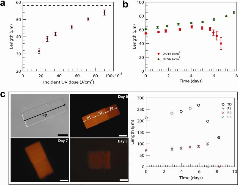
Figures 4a and b demonstrate that as the UV energy dose increases, the initial particle size increases slightly while the degradation profile changes dramatically. This evidence supports the hypothesis that oxygen inhibition effects are not confined to the axis of UV projection, but are also present in the lateral direction to a more subtle extent. Oxygen diffusion from the saturated monomer solution beyond the field of exposure establishes a lateral oxygen gradient that inhibits polymerization at the edges and affects the final particle dimension at lower UV doses. At higher UV doses, the edge effect can be observed to diminish as the initial particle size approaches the dimensions of the projected UV cross sectional area (a 58 × 58 × 58 μm3 triangle) as shown in Figure 4a. The effect of UV dose is also apparent in the erosion profile displayed by microhydrogels over time. Figure 4b illustrates the change in erosion behavior as the UV exposure dose is increased. At a lower dose, particles are observed to “shrink” over time. As higher UV doses are applied, a transition is observed above which particles display more classical behavior typical of macroscale bulk eroding hydrogels. Hydrogel particles formed at high UV doses display erosion behavior that is independent of particle size and shape (see Figure S1). We suggest that the observed reduction in particle size is due to a heterogeneous cross-linking density profile across particles, which arises from oxygen inhibiting polymerization near the mask edges. To demonstrate this behavior, we used grayscale lithography to fabricate a composite hydrogel particle with three distinct regions, each of which was polymerized under different UV exposure conditions using a grayscale photomask. The photomask allowed for the fabrication of monolithic particles with varying cross-linking density in three different regions of a slab by spatially attenuating the UV intensity that reached the solution. Figure 4c shows that the measured composite behavior is different from that of each individual block, which display a range of erosion behavior. The collective erosion profile of the composite particle is qualitatively similar to those particles fabricated with lower UV doses reported in Figure 3c. This trend supports our hypothesis that cross-linking density is dramatically affected by the UV exposure dose, which in turn influences the mass loss profile.
Figure 4.
(a) Size dependence of degradable hydrogel formation (20 wt % diacrylate PLA-b-PEG-b-PLA) on UV exposure dose and swelling behavior of (a) degradable hydrogels (20 wt % diacrylate PLA-b-PEG-b-PLA) fabricated with increasing UV exposure dose and (c) degradable hydrogels (diacrylate PLA-b-PEG-b-PLA 30 wt %) with a heterogeneous crosslinking density profile. (c) Particles are formed using a grayscale photomask (high to low UV transparency from R1 to R3); top-left and -right images show bright-field and fluorescent optical images of the particles on day zero, and arrows indicate the total dimension (TD) and three distinct regions (R1, R2, and R3) with crosslinking density gradients plotted on the right. Scale bars are all 50 μm. Error bars in (c) are within the marker size.
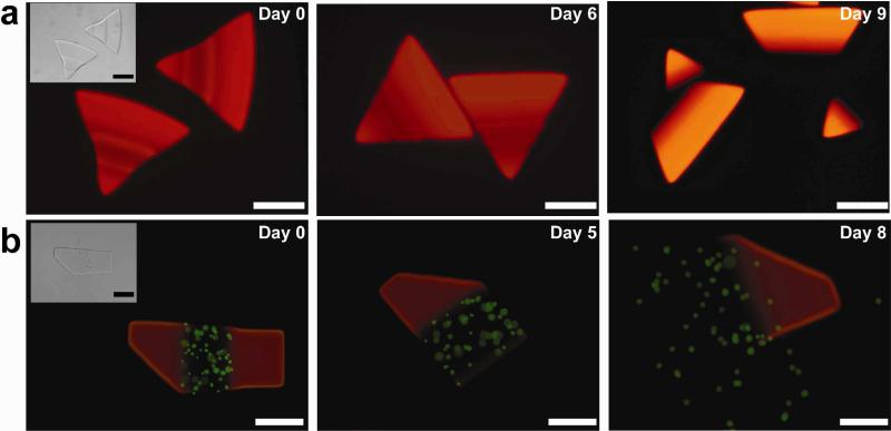
In addition to our ability to tailor the dimension, shape and erosion profile of degradable hydrogel microparticles, we demonstrate that these parameters can be tuned independently (Figure S1). More importantly, SFL allows for the generation of particles with multi-funtionalities by simply co-flowing multiple streams through a microchannel and patterning across these diffusion-limited laminar streams17,18. Furthermore, by controlling each stream's flow rate, adjusting the polymerization location and choice of photomask, we can easily generate a single particle containing several adjacent chemistries with control over proportion and pattern of each chemistry. Figure 5 illustrates additional demonstrations of spatial patterning within degradable hydrogel microparticles. Here, degradable bridges connecting non-degradable blocks and/or multi-degradable blocks erode in a programmable manner. In one example, the erosion of the center block releases the non-degradable blocks into two morphologically-distinct elements. In a second demonstration, each block dissolve in a specific time frame and fluorescently-labeled polymer microspheres are released upon the erosion of the center block.
Figure 5.
Composite hydrogels: (a) Heterogeneous hydrogel particles formed by SFL spanning three distinct co-flowing streams: diacrylate PLA-b-PEG-b-PLA 20 wt % in the middle stream and PEGDA 30 wt % in each side stream. (b) multi-block hydrogels formed by coflowing three streams of different diacrylate PLA-b-PEG-b-PLA concentrations: from the left on Day 0, PEG-b-PLA 30 , 20 , and 10 wt % . In the middle stream, fluorescent beads with a diameter of 2 μm are encapsulated. Scale bars are all 50 μm. Inserts top-left on day zero show bright-field optical images of the hydrogels.
Conclusions
We have reported the application of a microfluidic photolithograpy platform to the creation of degradable PEG-based hydrogel microparticles. Stop-flow lithography has been used to fabricate particles of independently tunable size, shape and erosion profile. Particles of varying size and shape have been fabricated and their degradation behavior has been characterized histologically and mechanically. Additionally, we demonstrate that the applied UV energy dose is a parameter that can be tuned to affect the time-dependent spatial profile of mass loss within single hydrogel particles. More importantly, this method allows us to pattern multiple distinct degradation regions in single hydrogel microparticles with custom erosion profiles that can be used to directly encapsulate therapeutics for targeted delivery with great overall design flexibility. These particles are of considerable interest for fundamental materials science investigations of tunable erosion in hydrogels and applied studies in tissue engineering and drug delivery.
Supplementary Material
Acknowledgements
We gratefully acknowledge the support of NSF NIRT Grant No. CTS-0304128 and the Singapore-MIT Alliance (SMA-II, CPE Program) for this project. D.K. Hwang acknowledges the support from the Natural Sciences and Engineering Research Council of Canada (NSERC) for NSERC Postdoctoral Fellowship. J.O. acknowledges funding under NIH-P41EB002503.
Footnotes
Supporting Information available: Materials and Methods, Figure S1, and Figure S2. This information is available free of charge via the Internet at http://pubs.acs.org/.
References
- 1.Chiellini F, Petrucci F, Ranucci E, Roberto S. In: Biomedical Polymers and Polymer Therapeutics. Chiellini E, Sunamoto J, Migliaresi C, Ottenbrite R, Cohn D, editors. Springer US; New York: 2001. pp. 63–74. [Google Scholar]
- 2.Saito H, Hoffman AS, Ogawa HI. J. Bioact. Compat. Polym. 2007;22:589–601. [Google Scholar]
- 3.Cushing MC, Anseth KS. Science. 2007;316:1133–1134. doi: 10.1126/science.1140171. [DOI] [PubMed] [Google Scholar]
- 4.Ainslie KM, Kraning CM, Desai TA. Lab Chip. 2008;8:1042–1047. doi: 10.1039/b800604k. [DOI] [PMC free article] [PubMed] [Google Scholar]
- 5.Khademhosseini A, Langer R, Borenstein J, Vacanti JP. Proc. Natl. Acad. Sci. U. S. A. 2006;103:2480–2487. doi: 10.1073/pnas.0507681102. [DOI] [PMC free article] [PubMed] [Google Scholar]
- 6.Koh WG, Revzin A, Pishko MV. Langmuir. 2002;18:2459–2462. doi: 10.1021/la0115740. [DOI] [PubMed] [Google Scholar]
- 7.Franzesi GT, Ni B, Ling YB, Khademhosseini A. J. Am. Chem. Soc. 2006;128:15064–15065. doi: 10.1021/ja065867x. [DOI] [PubMed] [Google Scholar]
- 8.Anna SL, Bontoux N, Stone HA. Appl. Phys. Lett. 2003;82:364–366. [Google Scholar]
- 9.Thorsen T, Roberts RW, Arnold FH, Quake SR. Phys. Rev. Lett. 2001;86:4163–4166. doi: 10.1103/PhysRevLett.86.4163. [DOI] [PubMed] [Google Scholar]
- 10.Dendukuri D, Tsoi K, Hatton TA, Doyle PS. Langmuir. 2005;21:2113–2116. doi: 10.1021/la047368k. [DOI] [PubMed] [Google Scholar]
- 11.Xu S, Nie Z, Seo M, Lewis P, Kumacheva E, Stone HA, Garstecki P, Weibel DB, Gitlin I, Whitesides GM. Angew. Chem.-Int. Edit. 2005;44:724–728. doi: 10.1002/anie.200462226. [DOI] [PubMed] [Google Scholar]
- 12.Luo D, Pullela SR, Marquez M, Cheng Z. Biomicrofluidics. 2007;1:034102–1-6. doi: 10.1063/1.2757156. [DOI] [PMC free article] [PubMed] [Google Scholar]
- 13.Workman VL, Dunnett SB, Kille P, Palmer DD. Biomicrofluidics. 2007;1:014105–1-9. doi: 10.1063/1.2431860. [DOI] [PMC free article] [PubMed] [Google Scholar]
- 14.Shepherd RF, Conrad JC, Rhodes SK, Link DR, Marquez M, Weitz DA, Lewis JA. Langmuir. 2006;22:8618–8622. doi: 10.1021/la060759+. [DOI] [PubMed] [Google Scholar]
- 15.Nie ZH, Xu SQ, Seo M, Lewis PC, Kumacheva E. J. Am. Chem. Soc. 2005;127:8058–8063. doi: 10.1021/ja042494w. [DOI] [PubMed] [Google Scholar]
- 16.De Geest BG, Urbanski JP, Thorsen T, Demeester J, De Smedt SC. Langmuir. 2005;21:10275–10279. doi: 10.1021/la051527y. [DOI] [PubMed] [Google Scholar]
- 17.Dendukuri D, Pregibon DC, Collins J, Hatton TA, Doyle PS. Nat. Mater. 2006;5:365–369. doi: 10.1038/nmat1617. [DOI] [PubMed] [Google Scholar]
- 18.Dendukuri D, Gu SS, Pregibon DC, Hatton TA, Doyle PS. Lab Chip. 2007;7:818–828. doi: 10.1039/b703457a. [DOI] [PubMed] [Google Scholar]
- 19.Pregibon DC, Toner M, Doyle PS. Science. 2007;315:1393–1396. doi: 10.1126/science.1134929. [DOI] [PubMed] [Google Scholar]
- 20.Shepherd RF, Panda P, Bao Z, Sandhage KH, Hatton TA, Lewis JA, Doyle PS. Adv. Mater. 2008;20:4734–4739. [Google Scholar]
- 21.Panda P, Ali S, Lo E, Chung BG, Hatton TA, Khademhosseini A, Doyle PS. Lab Chip. 2008;8:1056–1061. doi: 10.1039/b804234a. [DOI] [PMC free article] [PubMed] [Google Scholar]
- 22.Bryant SJ, Bender RJ, Durand KL, Anseth KS. Biotechnol. Bioeng. 2004;86:747–755. doi: 10.1002/bit.20160. [DOI] [PubMed] [Google Scholar]
- 23.Rice MA, Anseth KS. J. Biomed. Mater. Res. Part A. 2004;70A:560–568. doi: 10.1002/jbm.a.30106. [DOI] [PubMed] [Google Scholar]
- 24.Burdick JA, Anseth KS. Biomaterials. 2002;23:4315–4323. doi: 10.1016/s0142-9612(02)00176-x. [DOI] [PubMed] [Google Scholar]
- 25.Nuttelman CR, Benoit DSW, Tripodi MC, Anseth KS. Biomaterials. 2006;27:1377–1386. doi: 10.1016/j.biomaterials.2005.08.014. [DOI] [PubMed] [Google Scholar]
- 26.Nuttelman CR, Tripodi MC, Anseth KS. Matrix Biol. 2005;24:208–218. doi: 10.1016/j.matbio.2005.03.004. [DOI] [PubMed] [Google Scholar]
- 27.Nuttelman C, Tripodi M, Anseth KS. J. Biomed. Mater. Res. Part A. 2006;76A:183–195. doi: 10.1002/jbm.a.30537. [DOI] [PubMed] [Google Scholar]
- 28.Metters AT, Anseth KS, Bowman CN. Polymer. 2000;41:3993–4004. [Google Scholar]
- 29.Metters AT, Bowman CN, Anseth KS. J. Phys. Chem. B. 2001;104:7043–7049. [Google Scholar]
- 30.Metters AT, Anseth KS, Bowman CN. J. Phys. Chem. B. 2001;105:8069–8076. [Google Scholar]
- 31.Atencia J, Barnes S, Douglas J, Meacham M, Locascio LE. Lab Chip. 2007;7:1567–1573. doi: 10.1039/b709369a. [DOI] [PubMed] [Google Scholar]
- 32.Waits CM, Modafe A, Ghodssi R. J. Micromech. Microeng. 2003;13:170–177. [Google Scholar]
- 33.Wu MH, Park C, Whitesides GM. Langmuir. 2002;18:9312–9318. [Google Scholar]
- 34.Jeon NL, Baskaran H, Dertinger SKW, Whitesides GM, Van De Water L, Toner M. Nat. Biotechnol. 2002;20:826–830. doi: 10.1038/nbt712. [DOI] [PubMed] [Google Scholar]
- 35.Burdick JA, Khademhosseini A, Langer R. Langmuir. 2004;20:5153–5156. doi: 10.1021/la049298n. [DOI] [PubMed] [Google Scholar]
- 36.Dendukuri D, Panda P, Haghgooie R, Kim J, Hatton TA, Doyle PS. Macromolecules. 2008:8547–8556. [Google Scholar]
- 37.Mason MN, Metters AT, Bowman CN, Anseth KS. Macromolecules. 2001;34:4630–4635. [Google Scholar]
- 38.Clapper JD, Skeie JM, Mullins RF, Guymon CA. Polymer. 2007;48:6554–6564. [Google Scholar]
Associated Data
This section collects any data citations, data availability statements, or supplementary materials included in this article.


