Abstract
In high-field magnetic resonance imaging (MRI) systems, B0 fields of 7 and 9.4 T, the RF field shows greater inhomogeneity compared to clinical MRI systems with B0 fields of 1.5 and 3.0 T. In multichannel RF coils, the magnitude and phase of the input to each coil element can be controlled independently to reduce the nonuniformity of the RF field. The convex optimization technique has been used to obtain the optimum excitation parameters with iterative solutions for homogeneity in a selected region of interest. The pseudoinverse method has also been used to find a solution. The simulation results for 9.4- and 7-T MRI systems are discussed in detail for the head model. Variation of the simulation results in a 9.4-T system with the number of RF coil elements for different positions of the regions of interest in a spherical phantom are also discussed. Experimental results were obtained in a phantom in the 9.4-T system and are compared to the simulation results and the specific absorption rate has been evaluated.
Keywords: Convex optimization, high-field MRI, magnetic resonance imaging (MRI), pseudoinverse, parallel excitation, RF B1 field, transmission line head coil
INTRODUCTION
High-Field magnetic resonance imaging (MRI) systems, with static B0 fields of 4, 7, and 9.4 T, have higher signal to noise ratios (SNR) and higher resolution in the images [1], [2]. The frequency of the radio frequency (RF) excitation increases as 42.6 MHz/T for proton spins with B0 field, and for the above static field values these frequencies are now approximately 170, 298, and 400 MHz, respectively. Assuming that the average relative permittivity εr is approximately 70 in the human head [3], the wavelength is approximately 9 and 12 cm for B0 fields of 9.4 and 7 T, respectively. Nonuniformity of the RF magnetic B1 field excitation becomes a serious problem as the B0 field strength increases resulting in spurious contrast. The B1 field inhomogeneity is small in clinical MRI systems with B0 fields 1.5 and 3.0 T. Note that the field is the component of the RF field B1 and the other is the received image component.
To avoid spurious contrasts, MRI images require homogeneous fields in the subject and several investigations to minimize its nonuniformity have been published [4]-[11]. Traditional volume RF birdcage coils used in medical clinics with single channel excitation do not provide the additional degrees of freedom required to change the field distribution. Multichannel RF coils with parallel transmission lines with optimum excitation may alleviate the nonuniformity in the field. A photograph of a multichannel transmission line coil with individual elements is shown in Fig. 1(a). The amplitude and phase of the currents driving individual coil elements may be varied to develop the desired field distribution, though in some cases only the amplitudes or phases have been varied [2], [12].
Fig.1.
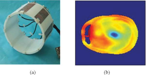
(a) Multichannel transmission line [transverse electromagnetic (TEM)] head coil and (b) results at 400 MHz (9.4 T).
This paper discusses two techniques of alleviating the inhomogeneity in by choosing sets of excitation parameters for the elements of RF multichannel coils. To determine these parameters, the individual map has to be obtained for the particular subject. The extraction of map from the image remains challenging in the high-field MRI systems [13]-[15]. This distribution of the varies with the subject and the optimization of the multichannel coil element excitation has to be performed for the every particular subject, and must be done rapidly.
In practice, it is difficult to obtain homogeneous fields over the whole field of view for systems with B0 field of 7 T and above. Instead, field uniformity is obtained over a region of interest (ROI) [12], [16], [17] and the optimal excitation parameters of the coil elements may be determined rapidly by convex optimization [18] or by the pseudoinverse method. The need to obtain rapid solutions is critical to minimize the time the subject spends in the MRI system. Additionally, convex optimization provides better fields in specific anatomic ROIs [19]. Although the results with convex optimization show these advantages, problems still remain, including high fields at the edges of the ROI and inhomogeneity in the suppression region. In our previous papers [20], [21], field localization results in the 9.4-T system were presented by using the convex optimization method and in this paper, we expand these and also provide optimization data in both 7.0- and 9.4-T MRI systems including analysis of the results with a different number of channels of the RF coil. In addition, the pseudoinverse method based on the singular value decomposition solution is used to find the optimal weights and compared to the convex optimization. The simulation results are compared with experiment in a spherical phantom in the 9.4-T system, in this case the specific absorption rate (SAR) is also evaluated.
In this paper, a modified approach of the convex optimization method with the addition of an iterative scheme is proposed. Next, the results of the pseudoinverse method are compared to those of the iterative convex optimization method. The results of the application of the methods to the 9.4-T system are compared to those in the earlier 7.0-T system. A cylindrical phantom, which results in a circle in an axial section is next used in the simulations and the optimization results for a 16-channel coil are compared to those from a 32-channel coil for the 9.4-T system. Finally, an experiment was performed using an eight-channel transmission line coil with a spherical phantom and the results confirm the theoretical predictions.
METHODOLOGY
The circularly polarized component of the RF B1 magnetic field inside the object is defined as [22]
| (1) |
where , Bx and By are the complex vectors of x and y directional RF magnetic fields, respectively. Bx and By are obtained by finite difference time-domain (FDTD) numerical simulations using the REMCOM XFDTD software (2 × 2 × 2.5 mm3 resolution). These simulations were performed at 300 and 400 MHz for the 7- and 9.4-T MRI system, respectively, in a head model and also in a phantom for a multichannel transmission line (TEM) coil [4]. The human head model developed by the REMCOM is a realistic and heterogeneous human head including 20 different tissue types (e.g., skin, blood, fat, muscle, gray matter, white matter, cerebrospinal fluid, and so on).
A. Convex Formulation
As shown in Fig. 1(b), the simulated field is very inhomogeneous at 400 MHz with uncontrolled 16 port excitations. The primary objective of this study is to increase the in a specific target region and also decrease the in the region outside, which is the suppression region [20], [21]. Since the field is proportional to the weights which is the linear amplitude and phase of the excitation current at each element, the circular positive polarized transmit field with wi at the ith element may be written for the total field representation. The following are basic convex formulations which satisfy the initial objective:
| (2) |
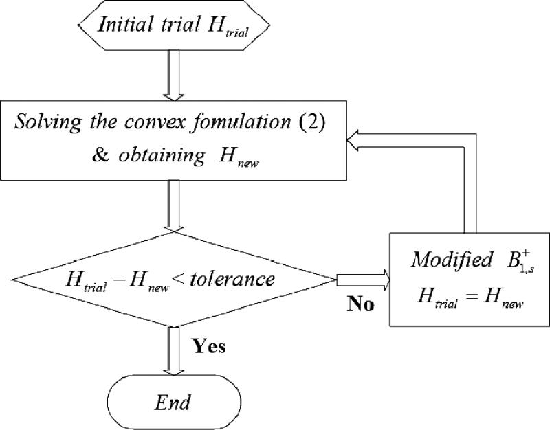
where and represent in the suppression region and at the center of the ROI, respectively. Equation (2) states the constraints for solving for the optimum w while still minimizing the maximum value of in the suppression region by setting the center value of to unity. From the aforementioned formulation, fields are more significant in determining the optimum w, since consists of a large number of field points, whereas is the field at only one point. Under these constraints, an appropriate selection of is required to obtain homogeneous suppression outside the point c, which alleviates anomalous contrasts. The solution w in (2) was calculated by CVX, which is a MATLAB routine for convex optimization programming and the newest version, SDP3 solver, is used [23]. To find the optimal , an iteration algorithm is used in combination with the convex formulation according to the flow chart.
B. Iterative Scheme
Based on the aforementioned convex optimization criterion, the selection of is critical to obtaining the value of w at the given . This is because these vector fields are correlated with each other in terms of the solution of w. The homogeneous coefficient H in the suppression region is defined as
| (3) |
where M(w) is an absolute mean value of the sum of all the elements of and n is the number of pixels in the suppression region. The homogeneous coefficient H represents the sum of the elements of , the homogenous field in the suppression region, and the lower H implies better homogeneity. The basic concept for the iteration algorithm is to minimize H.
As shown in Fig. 2, the iterations are performed by comparing the new homogeneous coefficient Hnew of the solution to Hold of the previous solution. The modification is repeated by searching the values close to near to the target region and excludes those vectors in the next iteration. The vectors with large near the target region cause spikes in the results. Therefore, discarding these vectors from the min–max convex optimization problem promotes RF field homogeneity. Each iteration takes approximately 4 s and overall computation time for 12–14 iterations is less than a minute (Intel Core2 Duo CPU 2.53 GHz). Efficient and fast solutions are particularly important when living human subjects are to be imaged because of the limited time between patient movements. Since the field maximum at the center of the target ROI is held to unity, it is reasonable that the fields near the center are close to unity and will decrease as the distance from the center increases. Accordingly, it is also important to observe the distance when is is obtained. This decay length depends on the static field strength B0 and a longer length may be predicted at lower B0 intuitively, it is related to the wavelength of the Larmor frequency in the ROI. By applying this property to the modification of , the relation which produces poor homogeneity between the object and subject function may be eliminated and better homogeneity in the suppression region can be obtained. The importance of the field homogeneity in the suppression region is for two reasons, the first is to reduce the spurious peak in the ROI periphery, which results in better image contrast. Second, the overall input power may be reduced by alleviating useless field distribution and normalizing details are discussed in the simulation results below.
Fig. 2.
In the flow chart of the iteration algorithm, the tolerance is compared between Htrial and Hnew after the modification of and it can be chosen depending on Htrial. Each iteration takes less than 4 s.
C. Pseudoinverse Method
The total field representation at a point in the human head model is where N is the number of coil elements, p is the number of pixels. Then, a set of linear equations in the matrix form can be written as
| (4) |
where elements of [D] are desired fields in the field of view. N = 16 and p = 6710 are used in simulations. Note that N = 16 means 31 degrees of freedom because each coil element has real and imaginary currents (16 amplitudes and 15 relative phases). Ideally, homogeneous fields over the whole field of view are required (i.e., D1 = D2 = ··· = Dp), however, it is difficult because the number of 2N is much less than the number of equations p. Instead, desired fields can be localized by defining elements of [D] as
| (5) |
where Dr and Dn are normalized fields in the localized region and the nonlocalized region, respectively, and n = 1,..., p, but r ≠ r. With the choice of elements in [D], (4) can be solved by using the pseudoinverse (or called generalized inverse) because is a rectangular matrix. This approach comes from the singular value decomposition solution to a set of simultaneous linear equations and the solution is the vector of smallest norm that minimize such that
| (6) |
where the superscript pinv. denotes the pseudoinverse.
II.SIMULATION RESULTS
The REMCOM XFDTD software was used to obtain the simulated field distribution for the 7 and the 9.4-T MRI systems at 300 and 400 MHz, respectively. Since the Bx and By complex data are generated from a single coil element of the 16-channel head coil, the total obtained by duplicating 16 datasets after transposing these geometrically for a symmetric phantom. For the head model, all single element excitations need to be simulated separately. All field components were generated in the axial plane section through the center of each subject with 120 × 120 and 90 × 90 grid points for the human head model and the phantom, respectively. When these values are calculated, the amplitude of the drive to each coil element is set to unity and the phase set to zero.
A. Human Head Model
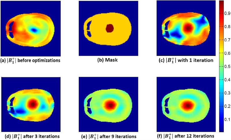
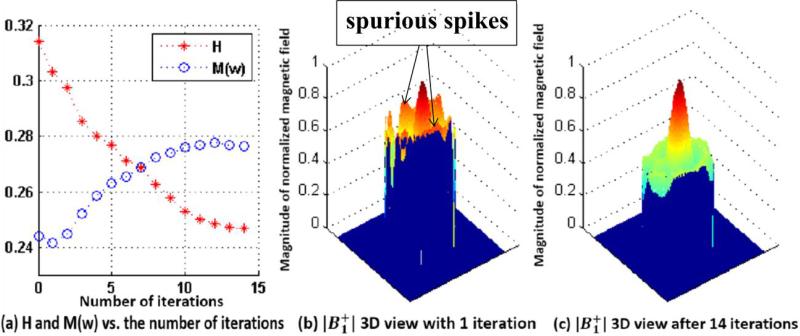
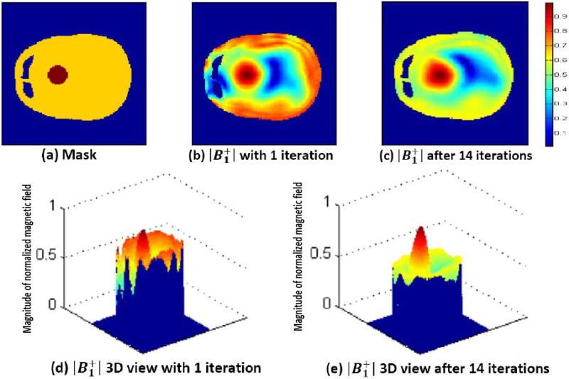
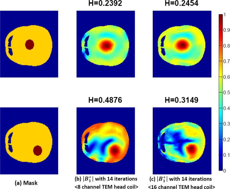
The results from the FDTD simulations on the human head model at 9.4 T are shown in Figs. 3, 4, 5, and 6. In these figures, the axial slices of the center of human head model are provided by XFDTD (version 6.0, Remcom, State College, PA). Figs. 3 and 4 show an improvement of the homogeneity in the suppression region when the target region [dark brown in Fig. 3(b)] is in the center. To alleviate the inhomogeneous field distribution in Fig. 3(a), the proposed method is applied for the field localization with the ROI in the center. As shown in Fig. 3(c), this distribution comes after solving (2), based only on the mask in Fig. 3(b). Although the field is desirable in the target region, it is not large enough to distinguish it from the noise of the whole region; this is due to poor homogeneity in the suppression region. To avoid this, the modified from new excitation parameters is applied iteratively. As seen in Fig. 3(c)– (f), the homogeneity is improved significantly, whereas on the target remains almost constant. In particular, these iterations reduce spurious spikes of view [see Fig. 4(b) and (c)]. The iterations of convex optimization are performed until the decrease of the homogeneity coefficient H becomes saturated. It also makes the absolute mean value M(w) in the suppression region somewhat larger [see Fig. 4(a)]. When the ROI moves to the edge of the field of view, the results are shown in Fig. 5. Similarly, results after iterations of convex optimization are shown in Fig. 5(c) and (e). The homogeneity in the suppression region is improved, but not as much as when the ROI was centered because of the lack of symmetry. Since weights are designed for the ROI located at the left, the opposite location has a relatively low field [see Fig. 5(b) and (c)]. As the target moves to the edge, this lack of symmetry becomes apparent and the coil with fewer channel coil elements may result in poor SNR images. To confirm this expectation, eight-channel head coil results are simulated and compared with 16-channel results in Fig. 6.
Fig. 3.
FDTD human head model results at 9.4 T (400 MHz) when the 16-channel head coil is used. (a) Initial field distribution without optimizations. (b) Head model mask and the ROIis in the center. (c) result with the convex optimization (1 iteration). (d)–(f) results after applying 3, 9, and 12 iterations.
Fig. 4.
(a) Homogeneous coefficient H and the absolute mean value M(w) in the suppression region depending on the number of iterations. (b) 3-D view with the initial convex optimization. (c) 3-D view after 14 iterations and it shows a lot of fields are he edge. suppressed, especially at the edge.
Fig. 5.
FDTD human head model results at 9.4 T (400 MHz) when the 16-channel head coil is used. (a) Head model mask and the ROI is shifted to the left. (b) and (d) results with the initial convex optimization (1 iteration). (c) and (e) results after 14 iterations.
Fig. 6.
FDTD human head model results at 9.4 T (400 MHz). (b) 8-channel and (c) 16-channel TEM head coil are used. Note that more homogeneous suppression regions in the 16-channel simulations are obtained. (a) Mask. (b) with 14 iterations 〈8 channel TEM head coil〉 . (c) with 14 iterations 〈16 channel TEM head coil〉.
B. Pseudoinverse Method Versus Iterative Convex Optimization Method
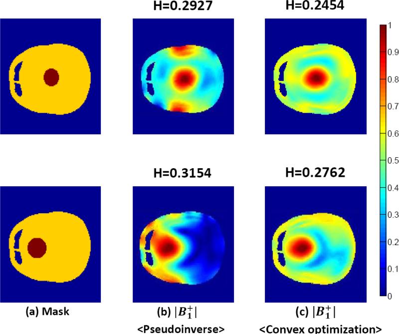
The pseudoinverse method is used to localize fields. As expected from (4) and (5), these results have good localizations in the ROI but inhomogeneous fields are distributed in the non-ROI regions as shown in Fig. 7(b). Since this method is based on matrix computations the solution w can be calculated within a few milliseconds. Compared to results obtained by the iterative convex optimization method [see Fig. 7(c)], the homogeneity coefficient of the pseudoinverse method for both ROI at the center and off the center is higher. The pseudoinverse method provides high in the ROI whereas the fields are fully suppressed in the non-ROI when ROI is off the center. It will be shown in detail in a subsequent paper that this property can be used to improve homogeneity over whole field of view.
Fig. 7.
localized results at 9.4 T (400 MHz) by the pseudoinverse and iterative convex optimization methods. Note that the 16-channel head coil is used and each map has been normalized to its own maximum value. (a) Mask. (b) 〈Pseudoinverse〉.(c) 〈Convex optimization〉.
C. 9.4 T Versus 7 T Formula Fields Inhomogeneity
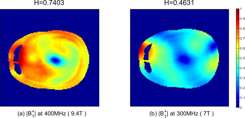
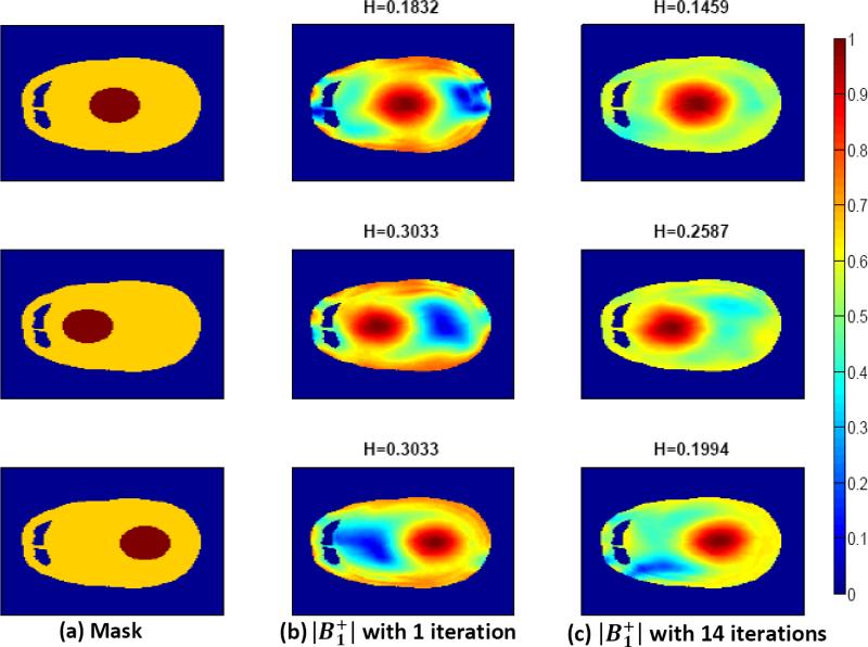
As the B0 magnetic field strengths increase, inhomogeneous B1 fields are expected to be higher due to interference effects in the human tissue. In particular, when a multichannel head coil with the same amplitude and phase of each coil is driven, the difference in inhomogeneity is observed in the simulated results (see Fig. 8). The weakest area, the blue colored, in 7 -T simulations is much larger than it is in 9.4.-T simulations. In terms of the homogenous coeffficient, the result at 9.4 T is 38% less homogeneous than the simulated result at 7 T. This lower homogeneity coefficient at 7 T means the target region (ROI) may be larger with the convex optimization. Compared to 9.4 T simulations in Figs. 3-6, Fig. 9 confirms this property, and should be considered when the target region size is selected. The detailed comparison of the target region size is analyzed by counting the number of pixels in the ROI. Table I shows that the number of pixels for 7 T is almost double the number of pixels for 9.4 T in each case. These findings explain that lower field strength systems provide larger ROIs for the B1 field in the head, virtually the whole field of view.
Fig.8.
simulated results when all weights are unity w1 = w2 = ··· = w16 = 1. H is a homogenous coefficient in the whole region due to no ROI. (a) at 400 MHz (9.4 T). (b) at 300 MHz (7 T).
Fig. 9.
FDTD human head model results at 7 T (300 MHz) when the 16-channel head coil is used. The relatively larger target regions in the 7-T simulations are obtained. (a) Mask. (b) with 1 iteration. (c) with 14 iterations.
TABLE I.
Comparison for the Number of Pixels in the ROI between 9.4 and 7 T Systems Through the Human Head Model.
| ROI is at the center | ROI is off center | |||
|---|---|---|---|---|
| The value of | 9.4T | 7T | 9.4T | 7T |
| 63 | 112 | 68 | 130 | |
| 141 | 274 | 146 | 270 | |
| 223 | 458 | 242 | 432 | |
| 323 | 634 | 339 | 606 | |
| 425 | 831 | 452 | 797 | |
| 530 | 1047 | 572 | 1022 | |
| 658 | 1298 | 720 | 1590 | |
The Total Number of Pixels in the Human Head Mask is 6710. The Calculations Were Performed Using the FDTD Model Where the Maximum Value of in the Slice is set to 1 at the Center of the ROI.
D. Phantom Model
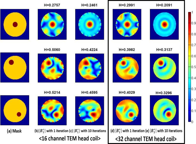
A 3-L sphere, with permittivity of 80 and conductivity of 1.1 S/m, is used as the phantom model for simulations [3]. The phantom model simulations are performed to compare the performance of a 16-element with that of a 32-element coil in a 9.4-T system. Similar to the human head model, the axial slice at the center of the phantom is used for the simulations. The phantom studies are different from the head model, as the phantom is perfectly symmetrical and less computational effort is required.
Fig. 10 illustrates the field distributions depending on the position of the ROI and compares the results from the 16 and 32 channel coils. In this simulation, three positions of the ROI are chosen as shown in Fig. 10(a). To solve the convex formulation in (2), is defined at the center of the ROI, initial fields contain all except in the ROI. With this choice, the simulation results for the central ROI show very similar results for both coils. When the ROI is located near the edge homogeneity in the outside ROI is poorer, especially for the 16-channel coil excitations [see Fig. 10(b)]. By applying the iterative method, Fig. 10(c) shows homogeneity improves by about 15 %, this is not acceptable. The 32-channel results are much better when compared to those from the 16-channel coil for all positions of the ROI. The homogeneity coefficient is also reduced by approximately 25–30% with the iterative method as shown in Fig. 10(d) and (e).
Fig. 10.
FDTD results at 9.4 T (400 MHz) in a phantom model. The 16-channel [(b) and (c)] and 32-channel TEM head coil [(d) and (e)] are used. Note that more homogeneous suppression regions in the 32-channel simulations are obtained.
III. EXPERIMENTAL RESULTS AND FUTURE WORK
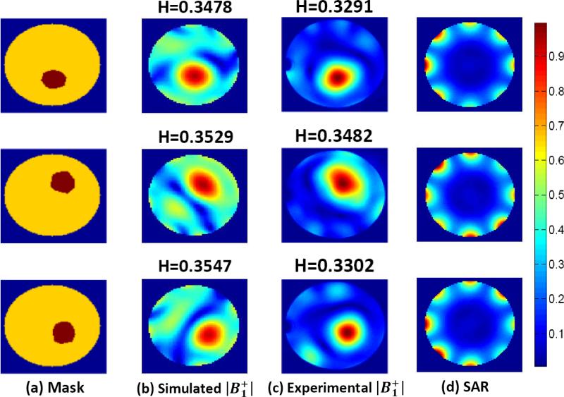
An experiment was performed using an eight-channel TEM head coil at the 9.4 T, 65-cm diameter bore system, with an asymmetric 40-cm diameter head gradient and shim set [2]. The phantom consists of a spherical container of 99-mM NaCl solution in water and its diameter is about 15 cm as discussed earlier. To collect a map, the double angle method was used [13]. With this method two scans are collected with different flip angles and an arcsin is applied to the ratio of the two. The normalized fields obtained for three different ROIs after convex optimization with the iterative method are shown in Fig. 11 and it shows a good agreement between simulations and experiments in the target. The agreement in the suppression region is relatively poor as only eight-channel coils are used in the measurement, and 16- and 32-channel experiments are not realizable at the current time. The pseudoinverse method was used for simulations in this experiment but it did not show good localizations due to fewer channel coil elements. Fig. 11(d) also shows the normalized values of the SAR defined by
| (7) |
where σ and ρ are the conductivity and the mass density of the phantom, respectively. The SAR results are slightly different along the edge of the phantom corresponding to the different ROIs. In general, the local SAR should be considered when B1 shimming is implemented. The RF shimming with the requirement of minimum SAR is the ultimate goal but both constrains cannot be satisfied in the convex formulation. Only preliminary results of the SAR calculations are included in this paper.
Fig. 11.
Simulated and experimental results at 9.4 T (400 MHz) in a spherical phantom. Measured fields are obtained for three different regions with the iterative method. (a) Mask. (b) Simulated . (c) Experimental . (d) SAR.
IV. CONCLUSION
High-field MRI systems offer advantages for numerous biomedical applications including high-resolution imaging of the human body. However, these systems have inhomogeneous field distributions since the wavelengths become smaller than the body. The RF field localization through convex optimization with an iterative method has been discussed by simulations on both the human head model and the spherical phantom with the multichannel TEM coil for the 7- and 9.4-T MRI systems, at 300 and 400 MHz, respectively. The pseudoinverse method has been also discussed and compared to the convex optimization by simulations. Excitation parameters of the coil elements were determined to obtain good fields in ROIs. The previous convex optimization without iterations generates fields in the target region, but has poor homogeneity in the suppression region. By applying the iterative method to the convex optimization, however, better homogeneity in the fields is obtained in the suppression region for both 9.4 and 7 T MRI systems. Simulations and experimental results show homogeneous ROIs obtained after the proposed method was implemented. Variations with the number of elements and different ROIs, and the SAR evaluation in the phantom have also been discussed.
Supplementary Material
ACKNOWLEDGMENTS
This work was supported in part by National Institutes of Health under Grant NIH R01-EB006835, in part by the Biotechnology Research Center under Grant BTRC P41-RR008079, in part by the Keck Foundation, and Basic Science Research Program through the National Research Foundation of Korea (NRF) funded by the Ministry of Education, Science and Technology under Grant 2011-0014776.
Biography
Hyoungsuk Yoo was born in Gyeongsan, Korea, in 1977. He received the B.S. degree in electrical engineering from Kyungpook National University, Daegu, Korea, in 2003, and the M.S. and Ph.D. degrees in electrical engineering from the University of Minnesota, Minneapolis, in 2006 and 2009, respectively.
In 2009, he was a Postdoctoral Associate with the Center for Magnetic Resonance Research, University of Minnesota. In 2010, he joined the Cardiac Rhythm Disease Management, Medtronic, MN, as a Senior MRI Scientist. He is currently an Assistant Professor in the Department of Biomedical Engineering, School of Electrical Engineering, University of Ulsan, Ulsan, Korea. His research interests include electromagnetic theory, numerical methods in electromagnetics, metamaterial, antennas, implantable devices, and magnetic resonance imaging in high magnetic field systems.
Dr. Yoo was awarded Third Prize for the Best Student Paper at the 2010 IEEE Microwave Theory and Techniques Society International Microwave Symposium.
Anand Gopinath (S’64–M’65–SM’80–F’90–LF’02) received the Ph.D. and D.Eng. (higher doctorate) degrees by the University of Sheffield, U.K.
He was Reader in Electronics at the University College of North Wales (1978), and also held the Chair of Electronics in Chelsea College, now merged with King's College (1981–1982), University of London, London. He was Research Staff Member at MIT Lincoln Laboratory (1978–1981, 1982–1986), and then joined the University of Minnesota as Professor of Electrical and Computer Engineering. He was Director of the Microelectronics Laboratory (now the Nano Fabrication Center), University of Minnesota, in 1989–1994. He has performed research in the field of RF/microwaves, and published extensively in the areas of guided wave structures, devices and circuits, and has recently directed a project in the area of scattering. He has also worked in the Integrated Optics and Optoelectronics areas, and he has published on a variety of devices and modeling in the area. His most recent projects are on very fast Analog to Digital Converters in CMOS, electromagnetic wave scattering from high dielectric constant cubes and MRI RF coils. He is Fellow of Optical Society of America and also Fellow of IET, London.
J. Thomas Vaughan (M’08) received the two B.S. degrees in electrical engineering and biology at Auburn University, Birmingham, AL, and the Doctoral degree in biomedical engineering from the University of Alabama at Birmingham, Birmingham, in 1993.
After receiving the degree, he joined Kennedy Space Center at NASA. Following the first Space Shuttle launch, he was recruited for a DOD project at Texas Instruments in Dallas before continuing his graduate education and employment at the University of Texas Southwestern. Here, he was the RF Engineer on a project to construct the first 2 T human NMR system begun in 1984.
In 1989, he took the post of the Chief Engineer for a University of Alabama Philips Research Labs consortium to build the first 4T system sited in the U.S.
After receiving the Doctoral degree, he became an Assistant Professor at Harvard University and Assistant in Physics and Director of Engineering at the Massachusetts General Hospital NMR Center. Following a four year term at the MGH to help commission a 3 T system and launch a 7 T program, he accepted tenure at the University of Minnesota in 1999 where he continues his work at 4 T, 7 T, 9.4 T, and beyond. He is currently a Professor in the Departments of Radiology, Electrical Engineering and Biomedical Engineering, University of Minnesota, Minneapolis.
Dr. Vaughan administers the Engineering Core of the Center for Magnetic Resonance Research.
REFERENCES
- 1.Vaughan J, Garwood M, Collins C, Liu W, DelaBarre L, Adriany G, Anderson P, Merkle H, Goebel R, Smith M, Ugurbil K. 7 T vs. 4T: RF power, homogeneity and signal to noise comparison in head images. Magn. Reson. Med. 2001;46:24–30. doi: 10.1002/mrm.1156. [DOI] [PubMed] [Google Scholar]
- 2.Vaughan J, DelaBarre L, Snyder C, Tian J, Akgun C, Shrivastava D, Liu W, Olson C, Adriany G, Strupp J, Anderson P, Gopinath A, Moortele P. 9.4 T human MRI: Preliminary results. Magn. Reson. Med. 2006;56:1274–1282. doi: 10.1002/mrm.21073. [DOI] [PMC free article] [PubMed] [Google Scholar]
- 3.Collins C, Yang Q, Wang J, Zhang X, Liu H, Michaeli S, Zhu X, Adriany G, Vaughan J, Anderson P, Merkle H, Ugurbil K, Smith M, Chen W. Different excitation and reception distributions with a single-loop transmit-receive surface coil near a head sized spherical phantom at 300 MHz. Magn. Reson. Med. 2002;47:1026–1028. doi: 10.1002/mrm.10153. [DOI] [PubMed] [Google Scholar]
- 4.Vaughan J. RF coil for imaging system. 2012 U.S. Patent 6 633 161, 2003.
- 5.Wang S, Murphy-Boesch J, Merkle H, Koretsky A, Duyn J. B1 homogenization in MRI by multilayer coupled coils. IEEE Trans. Med. Imaging. 2009 Apr.28(4):551–554. doi: 10.1109/TMI.2008.2006523. [DOI] [PMC free article] [PubMed] [Google Scholar]
- 6.Abraham R, Ibrahim T. Proposed radiofrequency phased-array excitation scheme for homogenous and localized 7-Tesla whole body imaging based on full-wave numerical simulations. Magn. Reson. Med. 2007;57:235–242. doi: 10.1002/mrm.21139. [DOI] [PubMed] [Google Scholar]
- 7.Ibrahim T, Lee R, Baertlein B, Abduljalil A, Zhu H, Robitaille P. Effect of RF coil excitation on field inhomogeneity at ultra high fields: A field optimized TEM resonator. Magn. Reson. Med. 2001;19:1339–1347. doi: 10.1016/s0730-725x(01)00404-0. [DOI] [PubMed] [Google Scholar]
- 8.Ibrahim T, Mitchell C, Schmalbrock P, Lee R, Chakeres D. Electromagnetic perspective on the operation of RF coils at 1.5-11.7 Tesla. Magn. Reson. Med. 2005;54:683–690. doi: 10.1002/mrm.20596. [DOI] [PubMed] [Google Scholar]
- 9.Li B, Liu F, Crozier S. Focused, eight-element transceive phased array coil for parallel magnetic resonance imaging of the chest. Magn. Reson. Med. 2005;53:1251–1257. doi: 10.1002/mrm.20505. [DOI] [PubMed] [Google Scholar]
- 10.Magill A, Wilton B, Jones A, McKirdy D, Glover P. A multiple element probe and sequential pulse sequence for ultra high field imaging—An improvement in B1 homogeneity. Proc. 13th Annu. Meeting ISMRM; FL. 2005. [Google Scholar]
- 11.Setsompop K, Wald LL, Alagappan V, Gagoski BA, Adalsteinsson E. Magnitude least squares optimization for parallel radio frequency excitation design demonstated at 7 telas with eight channels. Magn. Reson. Med. 2008;59:908–915. doi: 10.1002/mrm.21513. [DOI] [PMC free article] [PubMed] [Google Scholar]
- 12.Moortele P, Akgun C, Adriany G, Moeller S, Ritter J, Collins C, Smith M, Vaughan J, Ugurbil K. B1 destructive interferences and spatial phase patterns at 7 T with a head transceiver array coil. Magn. Reson. Med. 2005;54:1503–1518. doi: 10.1002/mrm.20708. [DOI] [PubMed] [Google Scholar]
- 13.Insko E, Bolinger L. Notes mapping of the radiofrequency field. J. Magn. Reson. 1993;103:82–85. [Google Scholar]
- 14.Brunner D, Pruessmann K. B1 interferometry for the calibration of RF transmitter arrays. Magn. Reson. Med. 2009;61:1480–1488. doi: 10.1002/mrm.21893. [DOI] [PubMed] [Google Scholar]
- 15.Sacolick L, Wiesinger F, Hancu I, Vogel M. B1 mapping by Bloch-Siegert shift. Magn. Reson. Med. 2010;63:1315–1322. doi: 10.1002/mrm.22357. [DOI] [PMC free article] [PubMed] [Google Scholar]
- 16.Mao W, Smith M, Collins C. Exploring the limits of RF shimming for high-field MRI of the human head. Magn. Reson. Med. 2006;56:918–922. doi: 10.1002/mrm.21013. [DOI] [PMC free article] [PubMed] [Google Scholar]
- 17.Metzger G, Snyder C, Akgun C, Vaughan J, Ugurbil K, Moortele P. Local B1 shimming for prostate imaging with transceiver arrays at 7 T based on subject-dependent transmit phase measurements. Magn. Reson. Med. 2008;59:396–409. doi: 10.1002/mrm.21476. [DOI] [PMC free article] [PubMed] [Google Scholar]
- 18.Boyd S, Vandenberghe L. Convex Optimization. Cambridge Univ. Press; Cambridge, U.K.: 2004. [Google Scholar]
- 19.Olson C, Yoo H, Delabarre L, Vaughan JT, Gopinath A. RF B1 field localization through convex optimization. Microw. Opt. Technol. Lett. 2012 Jan.54(1):31–37. [Google Scholar]
- 20.Yoo H, Gopinath A, Vaughan J. RF B1 field localizations at 9.4 T through convex optimization with an iterative method. Proc. 17th Annu. Meeting ISMRM; Hawaii. 2009. [Google Scholar]
- 21.Yoo H, Gopinath A, Vaughan J. A Method to control non-uniformity RF B1 field for high field magnetic resonance imaging. Int. Microwave Symp.; CA, USA. 2010. [Google Scholar]
- 22.Collins C, Smith M. Signal-to-noise ratio and absorbed power as functions of main magnetic field strength, and definition of “90°” RF pulse for the head in the birdcage coil. Magn. Reson. Med. 2001;45:684–691. doi: 10.1002/mrm.1091. [DOI] [PubMed] [Google Scholar]
- 23.Grant M, Boyd S. CVX: Matlab software for disciplined convex programming. 2007 http://stanford.edu/boyd/cvx.
Associated Data
This section collects any data citations, data availability statements, or supplementary materials included in this article.


