Abstract
An automated system for mounting and dismounting pre-frozen crystals has been implemented at the Stanford Synchrotron Radiation Laboratory (SSRL). It is based on a small industrial robot and compact cylindrical cassettes, each holding up to 96 crystals mounted on Hampton Research sample pins. For easy shipping and storage, the cassette fits inside several popular dry-shippers and long-term storage Dewars. A dispensing Dewar holds up to three cassettes in liquid nitrogen adjacent to the beam line goniometer. The robot uses a permanent magnet tool to extract samples from, and insert samples into a cassette, and a cryo-tong tool to transfer them to and from the beam line goniometer. The system is simple, with few moving parts, reliable in operation and convenient to use.
Introduction
Many crystallographic projects would benefit enormously from more efficient ways of screening large numbers of crystals. As screening is typically one of the most tedious steps of a structure determination, the quality of the crystal selected for data collection can depend more on the patience of experimenters than on the number of samples available. This burden can be particularly onerous for researchers studying membrane proteins or macromolecular assemblies, such as viruses, as this often requires characterizing hundreds of crystals (Cramer et al., 2000; Chang & Roth, 2001).
Other efforts such as structure-guided drug discovery and structural genomics will soon be producing crystals in even larger quantities. Researchers in the pharmaceutical industry have previously been content with only a few protein-inhibitor structures for a particular enzyme; however, modern techniques for rational drug design require many (Goodwill et al., 2001; Stewart et al., 2002). Several structural genomics research centres are now targeting thousands of novel macromolecular structures (Stevens et al., 2001) and they are starting to generate large numbers of crystals from highly automated protein production facilities (Stevens, 2000a). These centres are employing robotically controlled crystallization systems capable of setting up 100,000 crystallization trials per day (Stevens, 2000b; Luft et al., 2001). Furthermore, the technology that is emerging from the structural genomics efforts will soon feed back into both the academic and industrial communities, where it will enhance their ability to generate an ever increasing number of crystals (Stevens & Wilson, 2001).
As the intense, high-brightness X-rays from synchrotrons are well suited both to high-speed data collection and to obtaining data from poorly-diffracting samples, these trends have led to a concomitant rise in the demand for synchrotron beam time (Kuller et al., 2002). In order to meet this need, facilities have been constructing new crystallography beam lines, including several at third generation synchrotron sources, and obtaining CCD-based area detectors with readout times approaching one second (Phillips et al., 2000). The intense X-ray beam at such stations, combined with a fast detector, allows high quality diffraction images to be collected in only a few seconds and complete data sets in a matter of minutes (Walsh et al., 1999).
Despite these improvements, the demand for protein crystallography beam time continues to exceed the supply. As the mounting and dismounting of crystals at the beam line is currently a significant bottleneck, the efficiency of beam time utilisation can be further improved by addressing this step. At present, researchers must manually search through their shipping Dewar to locate and retrieve the desired crystal. Personnel safety systems must be disengaged before the experimental enclosure can be entered and must then be reactivated before the sample can be exposed to X-rays. At best, this operation takes several minutes per crystal and this rate is difficult to sustain over long periods. Thus, an automated method of mounting samples onto the beam line goniometer is highly desirable and will have a dramatic impact on throughput. A beam line with this capability would also allow full remote control of the experiment and unattended data collection would become feasible (Kuhn & Soltis, 2001).
At SSRL, there are currently five beam lines dedicated to protein crystallography. They are equipped with state-of-the-art instrumentation including high speed CCD detectors such as the Quantum 315 from Area Detector Systems Corporation, combined with a sophisticated software control system providing a high degree of automation (Kuhn & Soltis, 2001; McPhillips et al., 2002). In the near future, the SPEAR-3 storage ring upgrade (Corbett et al., 2001) will dramatically increase the source brilliance. It is therefore clear that an automated sample mounting system is now essential to make the most effective use of these experimental facilities and several groups have begun the development of devices for this purpose, including at Abbott Laboratories (Muchmore et al., 2000) and the ALS/LBNL (Earnest, 2001).
In this paper we describe the design and implementation of a robotic crystal mounting system that was developed, and is now in use, at SSRL.
1. System overview
The sample mounting system is simple, with few moving parts, reliable in operation and convenient to use. The system consists of:
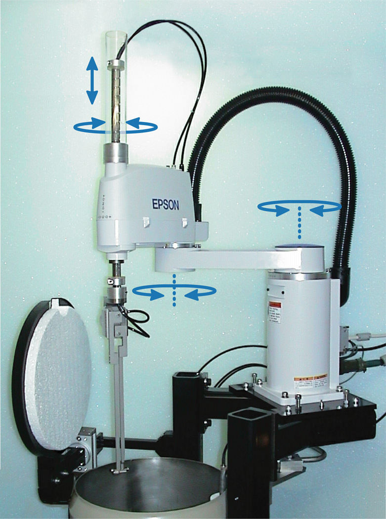
An industrial pick-and-place robot (figure 1) equipped with a pneumatic gripper actuator.
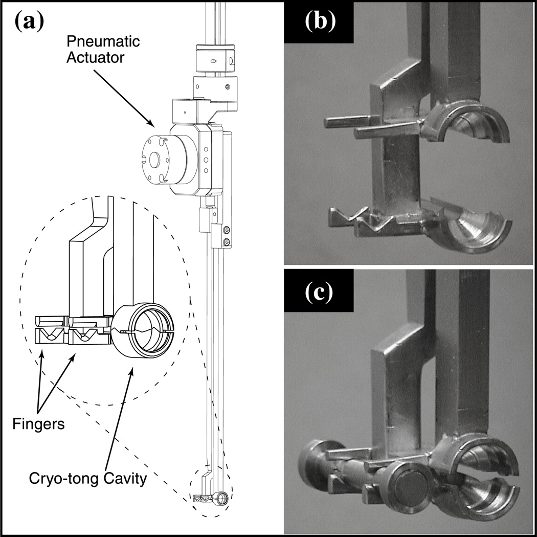
Two gripper arms mounted on the actuator (figure 2). The ends of these arms are similar to traditional cryo-tongs and are used to keep the sample cold during transfer. The tongs also incorporate two pairs of fingers that are used to grip a dumb-bell magnet tool (see 3).
The dumb-bell magnet tool being held by the gripper arms is shown in figure 2c. This tool is a small stainless steel rod with a strong permanent magnet at one end, used for extracting crystals from the cassette (see 4), and a weaker permanent magnet at the other, used for returning crystals to the cassette.
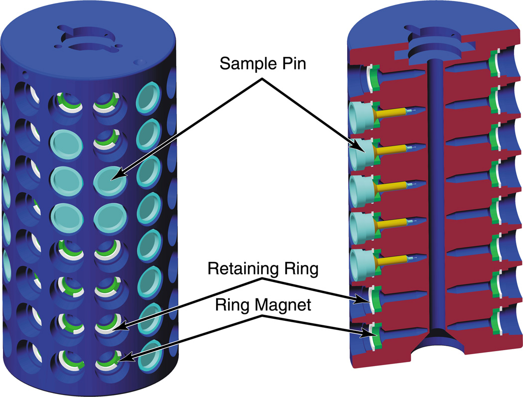
A cylindrical cassette (figure 3) with cavities to hold 96 sample pins. The pins are retained in the cassette by ring magnets.
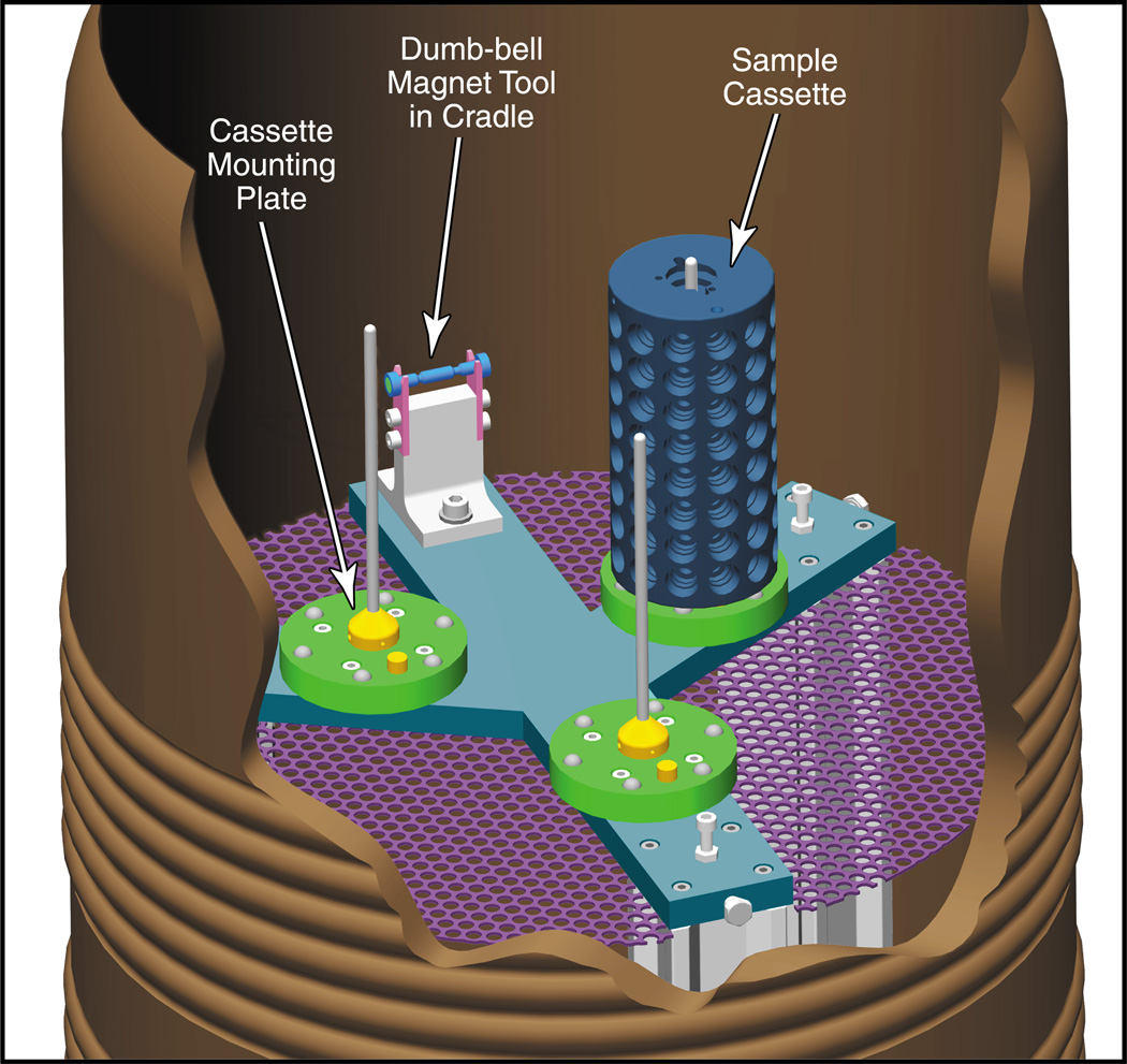
A dispensing Dewar (figure 4), which makes multiple cassettes available to the robot at the beam line and maintains them in a liquid nitrogen environment. It also incorporates a cradle for the dumb-bell magnet.
A tong de-icing system to remove ice and moisture from the tongs between robot mounting/dismounting operations.
Figure 1.
The Epson pick-and-place robot fitted with a pneumatic gripper actuator is shown. The four degrees of freedom are indicated by the arrows.
Figure 2.
(a) Schematic of the gripper arm assembly mounted on the actuator. (b) Detail of the cryo-tong in the open position. (c) The cryo-tong holding the dumb-bell magnet tool.
Figure 3.
The cylindrical cassette with cavities for 96 sample pins. The sectional view illustrates the details of construction.
Figure 4.
Cutaway diagram of the dispensing Dewar. Shown within the Dewar is an internal support stand with three cassette mounting plates and a cradle to hold the dumb-bell magnet tool.
1.1 Cassette mounting at the beam line
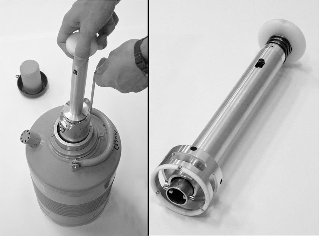
When a cassette is required at the beam line, it is transferred from the shipping or storage Dewar into the dispensing Dewar using a manual transfer handle (figure 5).
Figure 5.
Unloading a sample cassette from a Taylor Wharton CP100 shipping Dewar using the manual transfer handle.
The sequence of operations for mounting or dismounting a sample on the goniometer is illustrated in figure 6. The procedure for mounting a crystal is:
The Dewar lid is opened and the tongs are moved from the de-icer.
The robot cools the cryo-tongs in the liquid nitrogen, within the dispensing Dewar, for approximately 20 seconds.
The robot picks up the dumb-bell magnet from the dumb-bell cradle with the fingers projecting from the cryo-tongs.
The robot positions the strong end of the dumb-bell magnet adjacent to the required sample pin.
The dumb-bell is moved radially away from the cassette. The strong end of the dumb-bell magnet tool holds the pin more tightly than the ring magnet in the cassette and the sample is removed from the port.
The dumb-bell magnet tool, with the sample pin still attached, is returned to the cradle and is released by the tongs.
The cryo-tongs, which are now fully cooled, move to surround the sample pin and are then closed around it.
The tongs are rotated about a vertical axis to release the pin from the dumb-bell magnet; they are then moved swiftly out of the liquid nitrogen and towards the beam line goniometer.
The base of the pin is positioned against the goniometer head permanent magnet.
The tongs are opened and moved away from the goniometer, leaving the sample centred in the nitrogen cryo-stream.
The tongs are de-iced and dried in preparation for the next operation.
Figure 6.
The sequence of operations for (a) mounting or (b) dismounting a sample on the goniometer.
The entire mounting operation takes 40 seconds, not including the de-icing of the tongs, which takes an additional 40 seconds. The crystal is transported from under liquid nitrogen onto the goniometer in under 4 seconds.
The procedure for dismounting a crystal is:
The Dewar lid is opened and the tongs are moved from the de-icer.
The robot cools the cryo-tongs in the liquid nitrogen for 30 seconds.
The tongs are closed and moved swiftly out of liquid nitrogen and towards the sample position at the goniometer.
When the tongs are near the sample, they open, move to surround the pin, and then close.
The tongs are rotated about a vertical axis to release the pin from the goniometer magnet, and are rapidly transferred back to the dispensing Dewar.
The sample pin is placed onto the weak end of the dumb-bell magnet tool.
The tongs are opened to release the pin onto the dumb-bell magnet.
The robot picks up the dumb-bell magnet tool from the cradle.
The robot places the pin within the appropriate sample port.
The dumb-bell is moved radially away from the cassette. The cassette ring magnet holds the pin more strongly than the weak end of the dumb-bell magnet tool and the sample remains behind.
The dumb-bell magnet tool is returned to the cradle and is released by the tongs.
The tongs are removed from the dispensing Dewar and the lid is closed. The tongs are then warmed in the de-icer and dried in preparation for the next cycle.
The process takes approximately 45 seconds, not including de-icing and the tongs are out of liquid nitrogen for less than 7 seconds.
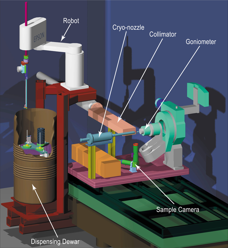
Systems of this type have been installed and successfully operated on beam lines 11-1 and 1–5 at SSRL (figure 7). The individual components are described in detail in section 2 below.
Figure 7.
Schematic representation of the robot as mounted at SSRL beamline 11-1. The cryo-cooler tank, transfer lines, and detector have been omitted for clarity. As in figure 4, the wall of the dispensing Dewar is cut-away to show the cassette locations.
2. Detailed System Description
2.1 The industrial robot
An off-the-shelf Epson ES553 4-axis robot (figure 1) was selected for sample manipulation. This model provides an adequate range of motion, but is still small enough to be conveniently accommodated at the beam line. The robot is equipped with three vertical rotation axes and a linear vertical translation shaft, all with absolute position encoders. The translation shaft is equipped with an SMC model MDHR2-30R pneumatic actuator that is used to open and close the cryo-tongs and the fingers that grip the dumb-bell magnet. The ES553 provides a maximum horizontal reach of 550 mm and a total vertical range of 320 mm, provided by an optional extended translation shaft. It is fast (for example, the vertical translation can move at 1000 mm.sec−1) and has a positional repeatability of ±20 µm in the horizontal plane and ±10 µm in the vertical (3σ values).
2.2 The gripper arms
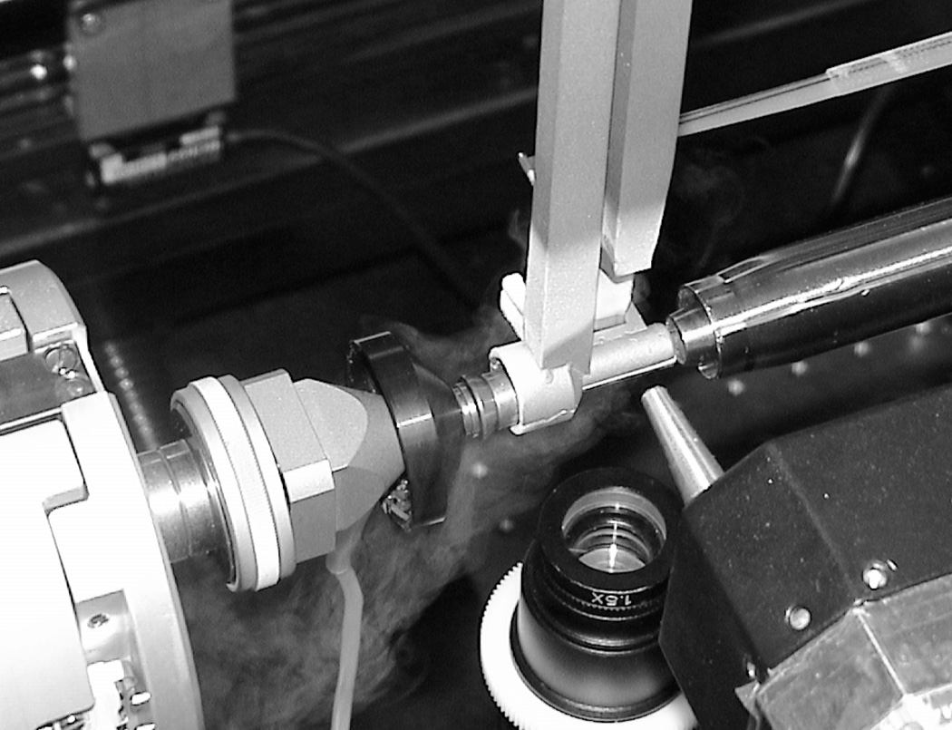
Two stainless steel arms link the SMC actuator, mounted on the robot, to a cryo-tong (figure 2), which surrounds and protects the crystal during transfer to and from the beam line goniometer. When the tong is closed, a lip retains the sample pin within the cryo-tong cavity as it is pulled away from a magnet. Two pairs of stainless steel fingers protrude from the cryo-tong and are used to pick up the dumb-bell magnet tool. When a standard 18 mm Hampton pin is used, the unprotected sample never lies more than 7 mm from the fixed cryo-cooler nozzle (figure 8).
Figure 8.
Cryo-tong delivering sample to the goniometer on beamline 1–5.
2.3 The dumb-bell magnet tool
The dumb-bell magnet tool is made of stainless steel and has magnets embedded in each end (figure 2c). A strong magnet (6.35 mm diameter × 2.54 mm, 18 MGOe SmCo) is used to remove sample pins from the cassette. A weak magnet (6.35 mm diameter × 1.74 mm, 18 MGOe SmCo, recessed 0.8 mm) is used to replace them. The tool resides in a cradle within the dispensing Dewar (figure 4) and is always submerged in liquid nitrogen.
2.4 The sample cassette
The sample cassette shown in figure 3 is a hard-anodized 6061 aluminium cylinder (64 mm diameter × 130 mm high) with 96 sample ports arranged as 8 rows of 12 ports encircling the cylinder. Each port accommodates a standard metal CrystalCap Magnetic™ or CrystalCap Copper Magnetic™ cryo-pin manufactured by Hampton Research. Each pin is held in place by a Ni-coated ring magnet (10.4 mm OD, 7.6 mm ID × 2.5 mm, 35 MGOe NdFeB). A Teflon retaining ring holds the magnet in place and also defines a 0.76 mm gap between the magnet and the cryo-pin, which ensures a constant magnetic holding force, independent of manufacturing variations in the pin dimensions. For added protection, when the pins are in place, they are recessed slightly below the cassette surface.
The thermal capacity of the cassette keeps the crystals close to liquid nitrogen temperature for a considerable time while the cassette is being transferred from one Dewar to another. The temperature at the crystal position within each port remains below 100K for more than two minutes after the cassette is removed from liquid nitrogen and placed at room temperature. It should be noted that it only takes approximately 5 seconds to transfer the cassette from a shipping Dewar to the dispensing Dewar.
The bottom of the cassette has a central conical depression that locates it on a mounting plate within the dispensing Dewar (2.5.1). A radial slot in the base of the cassette defines a unique orientation around the vertical axis. To aid in alignment when the cassette is mounted at the beam line, there is a corresponding index mark on the top. A central 6 mm diameter hole traverses the length of the cassette and accommodates a guide rod (see 2.5.1 below).
The top of the cassette has a machined aperture (figure 3) to accommodate a manual transfer handle (see figure 5, section 1.1). This handle locks into position allowing the cassette to be safely moved from the shipping Dewar to a storage Dewar or to the dispensing Dewar at the beam line.
2.4.1 Ideal Hampton pin lengths
The cassette has been designed to accommodate samples mounted on unmodified Hampton Research sample pins. Both the CrystalCap Magnetic™ and CrystalCap Copper Magnetic™ systems are supported. When the CrystalCap Magnetic™ system is used, MicroTube™ lengths of 14, 18 or 21 mm can be accommodated. When the CrystalCap Copper Magnetic™ system is used, 14, 16, 18 or 21 mm models can be used when fitted with a 10 mm long MicroTube™. The copper magnetic 18 mm length is recommended.
2.5 The dispensing Dewar
The dispensing Dewar (figure 4) is mounted on the same support frame as the robot and holds up to three cassettes in a bath of liquid nitrogen. It consists of a Taylor Wharton Kryos K3 Dewar fitted with an internal support stand. The stand has three cassette mounting plates and a cradle to hold the dumb-bell magnet tool.
2.5.1 The cassette mounting plate
A mounting plate (figure 4) is attached to the stand inside the dispensing Dewar at each cassette location. A 4.8 mm diameter vertical rod is attached to each mounting plate, extending upwards to just below the liquid nitrogen level. During loading, the rod is used to guide the cassette downwards through the liquid nitrogen and onto the plate. The bottom of the cassette rests on six stainless steel ball-bearings (figure 4) that are embedded in the plate. This reduced contact area minimizes the risk of the cassette tilting in the event that ice or debris has accumulated.
2.5.2 The dumb-bell magnet support cradle
The dumb-bell magnet support cradle shown in figure 4 is also attached to the shelf inside the dispensing Dewar. The dumb-bell magnet tool always rests on this support when it is not held by the gripper arms. It is here that the crystal is transferred from the strong end of the magnet to the cryo-tong, before it is mounted on the goniometer and also from the cryo-tong to the weaker magnet, on its return journey to the cassette.
2.5.3 Lid and auto-fill system
To reduce frost formation we have constructed a thermally insulating lid (figure 1) for the dispensing Dewar. This lid is opened and closed automatically during robot operation using an SMC rotary table, model MSQB30R-A90-XN. For loading and unloading cassettes, the lid can be controlled manually using a switch. The lid accommodates the liquid nitrogen transfer pipe and a level sensor of an American Magnetics, model 186, auto-fill system.
2.6 The cryo-tong de-icing system
A 60° C water bath is used to rapidly warm the tongs after a dismount/mount cycle. After the tongs have been warmed for 7 seconds, they are slowly extracted from the water bath as a high velocity air jet and warm air source dry the tongs. The entire de-icing process takes approximately 40 seconds. Generally this delay is not a factor in overall system throughput as the de-icing operation proceeds in parallel with crystal alignment and data collection.
2.7 Robot control software
Driver software for robot operation was developed in C++ using the SPEL+ libraries supplied by Epson. The state of the system is monitored using electronic feedback from position and pneumatic pressure sensors. External components such as the gripper actuator, Dewar lid actuator and the de-icing heater, with air jet, are controlled through solenoid valves and electronically controlled switches. All the inputs to, and outputs from, the robot electronics are optically isolated.
3. Shipping and cassette handling
To facilitate transport, two cassettes fit within the standard sample canister of an MVE model SC 4/2V dry-shipping Dewar. An angular cut to the internal metal canister eases cassette extraction and insertion using the manual transfer handle, but is not essential (figure 5). Other vapour shipping Dewars that can be used include the Taylor-Wharton CP-100 and CX-100, and International Cryogenics IC-7VS. Up to twenty sample cassettes can be conveniently stored inside a Taylor-Wharton HC-35 high-capacity storage refrigerator.
4. Commissioning results
Following installation on beam line 11-1 the prototype system was extensively tested. As described below, the tests demonstrated that it was reliable, maintained samples at cryogenic temperatures at all times, and was not prone to icing problems. Subsequently, it was successfully used to screen a large number of crystals.
Tests were first carried out to verify the reliability of the system. The Dewar was filled with liquid nitrogen and the location and orientation of each cassette position was calibrated. Three cassettes were loaded into the dispensing Dewar and pins were repeatedly dismounted into and mounted from all sample ports. This process ran continuously overnight with no failures.
A thermocouple, mounted in a Hampton CrystalCap Copper Magnetic™ cryo-pin, was then used to monitor the cryo-tong cavity temperature during the mounting and dismounting operations. For the transfer from the dispensing Dewar to the goniometer, the increase was less than 5K and the pin was delivered to the sample position at a temperature below that of the cold stream (100K). During the dismounting operation, a small transient increase of approximately 10K was observed as the cryo-tong briefly opened and closed around the sample, following which the temperature quickly equilibrated to <110K. This temperature was maintained during the transfer back to the dispensing Dewar. A similar temperature fluctuation was observed during manual dismounting of samples using standard Hampton cryo-tools. Consistent with these observations, no change in mosaicity was evident after dismounting and mounting several protein crystal samples.
The liquid nitrogen level was maintained in the dispensing Dewar for 6 weeks without experiencing problems due to ice accumulation. All visible ice particles sank below the cassette support shelf and did not interfere with the samples. After repeated mounting and dismounting of protein crystal samples, no ice was visible on the surface of the loop or in diffraction images. Some ice was observed to form around the outside rim of the dispensing Dewar and this will be addressed by adding a heating element.
After initial commissioning, and integration of the robot control software into the DCS/BLU-ICE control system at SSRL (McPhillips et al., 2002) the robot was employed for automated screening (Deacon et al., 2002) of a large number of crystals for the Joint Center for Structural Genomics collaboration (Lesley et al., 2002). In all, 617 crystals were examined. More details of the software integration and the screening results will be published separately.
5. Work in Progress / Future Developments
While the prototype system has been successfully tested and used for several months, work is underway on the following enhancements: (1) final integration of the robot into the standard beam line control system, (2) developing a method for more rapidly de-icing the tongs, (3) accommodating a greater variety of pin styles, (4) facilitating sample loading into cassettes, (5) providing a simple method of cassette identification, and (6) adding sensors to simplify calibration and to make the system fail-safe.
The robot has been integrated into the Distributed Control System (DCS) at SSRL (McPhillips et al., 2002), enabling it to be coordinated with the motion of other beam line hardware. To control robot operations, a user-friendly interface is being added to the SSRL BLU-ICE data collection software. In conjunction with this, a sample-tracking database enables the identity of the sample in each port of a cassette to be recorded and data collection parameters to be documented. This information will be accessible both through BLU-ICE and a web interface.
While the current cryo-tong heater system (2.6) reliably warms and de-ices the tongs, we would like to improve the warming/drying cycle time. We are currently testing several radiant, conductive and convection heating systems and may replace the existing cryo-tong heater.
Although the prototype mounting system was based on Hampton Research cryo-pins, other designs could be employed. To accommodate the pin used with the ALS robotic system, a modified ALS-style puck and a puck carrier have been developed in collaboration with the ALS. This carrier mounts in place of a cassette in the robot dispensing Dewar. Subject to demand, other cassettes may be designed and, if necessary, a different magnetic base, dumb-bell magnet tool, or cryo-tong (Epson provides an optional quick-change tooling adaptor that will facilitate exchanging the grippers) could also be used.
To simplify the task of manually loading crystals into cassettes, a desktop jig is being developed. This device will allow a cassette to be correctly positioned under liquid nitrogen and guide samples into a selected port. For higher volume applications, we also plan to provide an offline system employing a smaller robot. This system will permit an experimenter to cryo-cool a crystal by placing it on a magnetic post either in a cold nitrogen gas stream or in the robot Dewar. The sample will then be picked up by the robot and inserted into a cassette. This system will also provide an additional means for sorting from one cassette to another. Sorting will also be available at each beam line using the robotic crystal mounting system.
To track the many cassettes that will be used, an identification scheme using a “code pin” has been devised. The prototype code pin consists of a small metal rod which is turned to one of four possible diameters at several points along its length, mounted on a Hampton Research CrystalCap Magnetic cryo-base and located in port 1A of each cassette. After the cassette is placed into the dispensing Dewar, the robot will transport the code pin to the goniometer. The unique number of the cassette will then be determined by analysing the sample-viewing camera image.
Finally, we are investigating the use of additional sensors to simplify robot calibration and to reduce the risk of collisions. These include an ATI Industrial Automation Gamma force sensor located between the robot arm and the gripper assembly, and laser-based displacement sensors to monitor the location of the goniometer magnet. The force sensor will be used for automated calibration of cassette location and orientation and can also be used to determine the occupancy of all ports following insertion of a new cassette. The displacement sensors will permit accurate location of the goniometer magnet and also confirm the absence of a pin at the sample position prior to a mounting operation.
6. Conclusions
A prototype system installed at SSRL beam line 11-1 has been shown to work well. It has been replicated on beam line 1–5 and similar systems are being installed on beam lines 9-1, 9-2, and 11-3 and will be available for use during the 2002/2003 experimental run. We anticipate that this will have a profound effect on the overall productivity of the facility. Due to its simple design and flexible software control, it should also be relatively straightforward to implement on other experimental stations with different equipment and space limitations.
Acknowledgements
The authors would like to thank Michael Hollenbeck, John Kovarik and Ross Floyd for their part in the design and the machining of many of the mechanical components. We thank Vladimir Vinetskiy, Henry Meier and Renato Avelar for their help with the design and installation of the electronic components in the system, and Henry van den Bedem and Güenter Wolf for skilful programming. We also thank Mike Soltis, Peter Kuhn and Keith Hodgson for their leadership and support. Stanford Synchrotron Radiation Laboratory operations funding is provided by the U.S. Department of Energy, Office of Basic Energy Sciences. The SSRL Structural Molecular Biology Program is supported by the National Institutes of Health, National Center for Research Resources, Biomedical Technology Program, by the Department of Energy, Office of Biological and Environmental Research and by the National Institutes of Health, National Institute of General Medical Sciences that supports our Joint Center for Structural Genomics (JCSG) collaboration.
References
- Chang G, Roth CB. Science. 2001;293:1793–1800. doi: 10.1126/science.293.5536.1793. [DOI] [PubMed] [Google Scholar]
- Corbett W, Hettel R, Akre R, Bellomo P, Boyce R, Cadapan L, Cassel RL, Choi B, Dell'Orco D, Elioff T, Evans I, Fuller R, Kurita N, Langton J, Leyh G, Limborg C, Macnair D, Martin D, Medvedko E, Ng C, Nosochkov Y, Olsen J, Ortega M, Pappas GC, Park S, Rarback H, Ringwall A, Rodriguez P, Safranek J, Schwarz H, Scott B, Sebek J, Smith S, Tanabe J, Terebilo A, Wermelskirchen C, Yotam R. Proceedings of the 2001 Particle Accelerator Conference, Chicago. New Jersey: IEEE; 2001. pp. 2674–2676. [Google Scholar]
- Cramer P, Bushnell DA, Fu JH, Gnatt AL, Maier-Davis B, Thompson NE, Burgess RR, Edwards AM, David PR, Kornberg RD. Science. 2000;288:640–649. doi: 10.1126/science.288.5466.640. [DOI] [PubMed] [Google Scholar]
- Deacon A, Brinen L, Kuhn P, McPhillips S, McPhillips T, Miller M, van den Bedem H, Wolf G, Zhong J, Zhang Z. Acta Cryst. 2002;A58(Supplement):C299. [Google Scholar]
- Earnest TN. Personal communication. 2001 [Google Scholar]
- Goodwill KE, Tennant MG, Stevens RC. Drug Discovery Today. 2001;6:113–118. [Google Scholar]
- Kuhn P, Soltis SM. Nucl. Instrum. Methods Phys. Res., Sect. A. 2001;467:1363–1366. [Google Scholar]
- Kuller A, Fleri W, Bluhm WF, Smith JL, Westbrook J, Bourne PE. Trends Biochem. Sci. 2002;27:213–215. doi: 10.1016/s0968-0004(02)02056-x. [DOI] [PubMed] [Google Scholar]
- Lesley SA, Kuhn P, Godzik A, Deacon AM, Mathews I, Kreusch A, Spraggon G, Klock HE, McMullan D, Shin T, Vincent J, Robb A, Brinen LS, Miller MD, McPhillips TM, Miller MA, Scheibe D, Canaves JM, Guda C, Jaroszewski L, Selby TL, Elsliger M-A, Wooley J, Taylor SS, Hodgson KO, Wilson IA, Schultz PG, Stevens RC. Proc. Natl. Acad. Sci. USA. 2002;99:11664–11669. doi: 10.1073/pnas.142413399. [DOI] [PMC free article] [PubMed] [Google Scholar]
- Luft JR, Wolfley J, Jurisica I, Glasgow J, Fortier S, DeTitta GT. J. Cryst. Growth. 2001;232:591–595. [Google Scholar]
- McPhillips TM, McPhillips SE, Chiu H-J, Cohen AE, Deacon AM, Ellis PJ, Garman E, Gonzalez A, Sauter NK, Phizackerley RP, Soltis SM, Kuhn P. J. Synch. Rad. 2002 doi: 10.1107/s0909049502015170. accepted for publication. [DOI] [PubMed] [Google Scholar]
- Muchmore SW, Olson J, Jones R, Pan J, Blum M, Greer J, Merrick SM, Magdalinos P, Nienaber VL. Structure. 2000;8:243–246. doi: 10.1016/s0969-2126(00)00535-9. [DOI] [PubMed] [Google Scholar]
- Phillips WC, Stanton M, Stewart A, Qian H, Ingersoll C, Sweet RM. J. Appl. Cryst. 2000;33:243–251. [Google Scholar]
- Stevens RC. Structure. 2000a;8:177–185. [Google Scholar]
- Stevens RC. Curr. Opin. Struct. Biol. 2000b;10:558–563. doi: 10.1016/s0959-440x(00)00131-7. [DOI] [PubMed] [Google Scholar]
- Stevens RC, Wilson IA. Science. 2001;293:519–520. doi: 10.1126/science.293.5529.519. [DOI] [PubMed] [Google Scholar]
- Stevens RC, Yokoyama S, Wilson IA. Science. 2001;294:89–92. doi: 10.1126/science.1066011. [DOI] [PubMed] [Google Scholar]
- Stewart L, Clark R, Behnke C. Drug Discovery Today. 2002;7:187–196. doi: 10.1016/s1359-6446(01)02121-3. [DOI] [PubMed] [Google Scholar]
- Walsh MA, Dementieva I, Evans G, Sanishvili R, Joachimiak A. Acta Cryst. 1999;D55:1168–1173. doi: 10.1107/s0907444999003698. [DOI] [PubMed] [Google Scholar]


