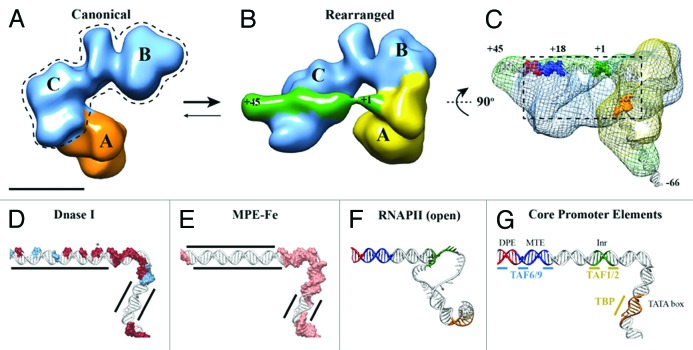
Figure 1. TFIID introduces topological changes in promoter DNA upon formation of the rearranged, DNA-bound conformation. Cryo-EM structures of the canonical conformation of TFIID (A) and the rearranged conformation of TFIID-TFIIA-SCP (B). The BC core is shown in blue, the flexible lobe A in orange (A) and yellow (B), and the SCP DNA in green (B). Promoter DNA positions +1 and +45 are indicated (B). (C) Mesh: Cryo-EM structure of TFIID-TFIIA-SCP(-66) rotated by 90 degrees relative to (B). The structure shows the location of DNA position -66 exiting lobe A. Positions -66, +1, and +45 are indicated and colored according to promoter motifs in (G). (D) DNase I footprint modeled onto the DNA path through TFIID-TFIIA-SCP. Red surfaces: full cleavage; blue surfaces: partial cleavage; (E) MPE-Fe footprinting modeled onto the DNA path through TFIID-TFIIA-SCP. Pink surface: cleavage; MPE-Fe protection by TFIID-IIA indicated by black lines. (F) DNA model from the open complex of TBP/PIC.34 (G) Promoter DNA model from TFIID-TFIIA-SCP colored by promoter motifs and TFIID subunits that make sequence-specific contacts.

An official website of the United States government
Here's how you know
Official websites use .gov
A
.gov website belongs to an official
government organization in the United States.
Secure .gov websites use HTTPS
A lock (
) or https:// means you've safely
connected to the .gov website. Share sensitive
information only on official, secure websites.
