Abstract
In this work, the aerodynamic performance of beetle wing in free-forward flight was explored by a three-dimensional computational fluid dynamics (CFDs) simulation with measured wing kinematics. It is shown from the CFD results that twist and camber variation, which represent the wing flexibility, are most important when determining the aerodynamic performance. Twisting wing significantly increased the mean lift and camber variation enhanced the mean thrust while the required power was lower than the case when neither was considered. Thus, in a comparison of the power economy among rigid, twisting and flexible models, the flexible model showed the best performance. When the positive effect of wing interaction was added to that of wing flexibility, we found that the elytron created enough lift to support its weight, and the total lift (48.4 mN) generated from the simulation exceeded the gravity force of the beetle (47.5 mN) during forward flight.
Keywords: beetle, elytra, forward flight, wing interaction, wing flexibility, computational fluid dynamics simulation
1. Introduction
The unsteady high force mechanism of a flapping wing including a leading edge vortex (LEV), rotational motion, wake capture and clap-fling has been unveiled [1,2]. Among them, the LEV is a crucial phenomenon; however, more studies are required of the spiral LEV [3] as well as the momentum transfer between the wing and the surrounding environment during three-dimensional flapping.
More recently, improving the aerodynamic performance of a flapping wing mimicking a flying insect has attracted the interest of researchers. Wing interaction characteristics and flexibility during the flapping motion are primary issues because they are believed to be the main reasons for the best aerodynamic performance of a flying insect. A great improvement in the aerodynamic force can be achieved from the interaction between two wings when they flap in appropriate parameters, including the gap between them, phase difference between the motions of two wings, and the amplitudes of their plunge motions [4–6]. Meanwhile, more studies are necessary in order to explore the aerodynamic performance caused by the interaction between flexible wings.
Wing flexibility is believed to be a key factor for improving the aerodynamic performance of insect flight. The wing of hoverflies is known to be dramatically deformed during the flapping period: the wing is positively cambered during the downstroke by trailing edge tension compressing the radial veins and negatively cambered with the tension released during the upstroke. The wing is also strongly twisted along the spanwise direction [7]. Walker et al. [7,8] conducted a detailed study of the deformable wing kinematics of hoverflies, including time-varying wing camber, twist and angle of incidence. In addition, the wing deformation of a dragonfly was assessed using a computational fluid dynamic model [9] to explore the improvement of its aerodynamic performance.
It is extremely difficult to build a numerical model to analyse the interaction between a wing surface and its surrounding air environment because the mechanics and mutual interactions of both the solid and fluid continua should be considered. Moreover, the solution should be convergent at every iterative step in both the solid and fluid domain. Alternative approaches are experimental studies or numerical computations of a simplified model. Recent research has shown that the twist angle indeed plays more significant roles than the camber in determining the aerodynamic forces during hovering flight by increasing the lift coefficient and reducing the required aerodynamic power [10]. When simplified wing-tip kinematics and angles of attack in the models of insect flight are used, the measured lift-to-drag ratio can be considerably reduced compared with when the original kinematics are used [11]. An experimental study of the effects on the aerodynamic force generation by wing flexibility showed that the net force on a flexible wing can increase or decrease through alternating sizing of the LEV by camber variation [12] during forward flight. Spanwise flexibility was found to be beneficial for thrust generation in a numerical study of flapping wing propulsion. The spanwise flexibility yields a small increase in the thrust coefficient and a small decrease in the power-input requirement, which results in higher efficiency [13]. Young et al. [14] analysed the aerodynamic forces of wing deformation in the locust using a commercial computational fluid dynamic (CFD) code with pre-described wing kinematics, later validating the numerical results through particle image velocimetry and smoke wire visualization methods. They found that a deformable wing achieved greater power economy than an un-cambered twisted model, which performed better than an untwisted model. There are also attempts to build up a systematic fluid–structure interaction (FSI) for highly flexible flapping wing [15,16]. A systematic analysis of the aerodynamic performance of a hovering hawkmoth, Manduca, was reported as the first successful FSI of a flapping insect [17]. The hovering efficiency of a flexible wing was found to be improved when twisting is considered.
Here, the aerodynamic performance of a flexible wing and elytra–hind wings interaction of a beetle are explored by a three-dimensional numerical simulation. The aerodynamics performance of the beetle owing to the previous two factors is an interesting research topic because its size is quite large compared with other insects, the hind wings are highly flexible, and the elytra are hard wings whose main function is the protection of the hind wing and the body. The aerodynamics of flexible hind wings in beetle flight is not fully known yet. Moreover, the aerodynamic role of the elytra is not well elucidated owing to their small size and great hardness. So far, the closing and opening mechanism of elytra as well as their geometry have been the main focus in previous studies [18,19]. The elevation of the prothorax was speculated to be the main mechanism in closing the elytra [20]. A simple method for analysing the aerodynamic performance of elytra has been published [21,22]. However, sophisticated studies of the aerodynamics in both wings are still required. The role of elytra in aerodynamics becomes more interesting when elytra–hind wing interaction is considered because the beetle has one active and one passive flapping wing, whereas other insects such as dragonfly and desert locust have two active wings.
In this study, flexible wing kinematics including twist and camber deformation is acquired through an experimental study, with the results used as the input for a CFD analysis. The kinematics of the elytra is captured in the study as well, and a simulation considering the interaction between a single elytron and the hind wing was then conducted in order to investigate the aerodynamic role of the elytron during flapping flight.
2. Materials and methods
2.1. Wing kinematics
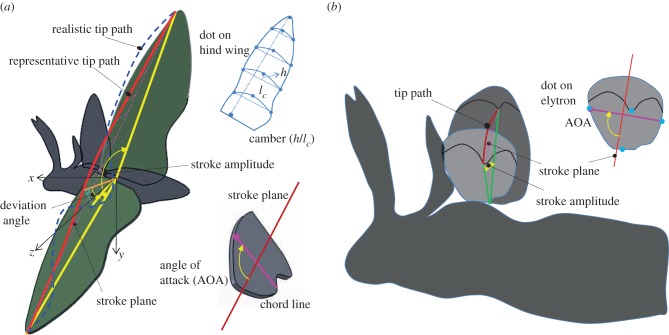
In our work, measured kinematics is used instead of simplified motions such as a sinusoidal function in order to investigate the aerodynamics of a realistic wing considering its flexibility. A male beetle is hung in the air inside a cubic chamber by a hook that is attached to the head of the beetle with cyanoacrylate glue. A cubic chamber of 50 × 50 × 50 cm is made of a transparent acrylic. Two high-speed cameras (Photron APX) are placed outside the chamber. One captures the front view and the other captures the side view. The camera is set to 2000 fps with a resolution of 1024 × 1024 pixels. Two halogen lamps of 1 KW power are positioned to illuminate the region near the beetle. Fourteen 1 mm white dots are marked on the hind wing and four dots are marked on the elytron as anatomical landmarks for digitization purposes, as shown in figure 1. After several minutes of suspension, the beetle initially flies freely, while two cameras recorded its motion. A modified direct linear transformation (DLT) method is used to merge two two-dimensional camera recordings in a single three-dimensional coordinate space. Then, the three-dimensional coordinate of each dot on the wings is analysed by the DLT method implemented in Matlab. The details of the experimental study can be found in our previous work [23]. In the practical experiment, we repeated the pre-described processes several times in order to obtain high-quality data. Finally, we use averaged values in the six cycles of the flapping wing in determining a stroke plane, a flapping angle, a stroke amplitude, a deviation angle and an angle of attack (AOA) for the hind wing and the elytron based on the dot's coordinates (x, y and z values).
Figure 1.
Definitions of terminologies in kinematics of (a) hind wing and (b) elytron. (Online version in colour.)
First of all, the stroke plane is defined as a plane which contains a wing-tip path connecting the top, bottom and middle positions during the cycle, which is called a representative tip path, as shown in figure 1a. The stroke angle is defined as the angle between the stroke plane and the horizontal plane namely, the zx plane. The span line is defined as a line connecting the selected dot near the wing tip and the selected dot near the wing root (thick yellow line in figure 1a). The flapping angle is defined as the angle between the span line and its projection on the horizontal plane. The stroke amplitude is defined as the angle between the span line when the wing tip is at the top position and the span line when the wing tip is the bottom position. The deviation angle is the angle between the span line and its projection onto the stroke plane (orange line in figure 1a). The deviation angle is used as the measure that indicates the difference of the instantaneous realistic tip path and the representative tip path, namely it shows the out-of-plane motion of the wing. The AOA is the angle between the chord line and the stroke plane. Furthermore, the camber is defined as the ratio of the mid-chord height (h) over the chord length (lc) at each section. Similarly, the kinematics terminology of the elytron is defined in figure 1b. The elytron is a rigid wing, so twist and camber variations are negligible and the deviation angle is almost 0°. Hence, the kinematics of the elytron is described by three parameters: the stroke angle, the flapping angle and the AOA. The stroke plane of the elytron and the flapping angle are defined by two dots at the tip and the root wing as shown in figure 1b. The AOA is the angle of the chord line, which connects two dots at the middle position along the spanwise direction on leading and trailing edge, and the stroke plane.
2.2. Numerical methods
2.2.1. Flow solver
The wing kinematics from pre-described experimental study was used as the input condition of a CFD code in an effort to investigate the aerodynamic performance of a beetle. The in-house code, termed KFLOW, is a parallelized multi-block-structured Navier–Stokes solver; several turbulent models are available. For the spatial discretization, the Roe flux difference slitting scheme and third-order MUSCL are used with Van Albada limiter to obtain secondary accuracy of inviscid flux. Meanwhile, the simple central difference is used to obtain variable gradient of viscous flux. The dual-time stepping with the diagonalized alternate directional implicit method is used to advance the solution in time. This allows not only the use of a large time increment but also the maintenance of temporal accuracy. In addition, dual-time stepping also eliminates factorization and linearization errors by iterating the solutions along a pseudo-time. The numerical detail has been described in previous works [24–27].
A Chimera mesh scheme was used to simulate a flapping wing because of its advantage in handling the relative motion between meshes [28]. In this Chimera overset method, a cut-paste algorithm is applied to compose a cross section that exchanges information between grids, which enables the generation of overlapping grids with moderate mesh interface regions. The overlapped grid method combines two major steps: hole cutting and donor identification [29].
2.2.2. Wing and kinematics modelling
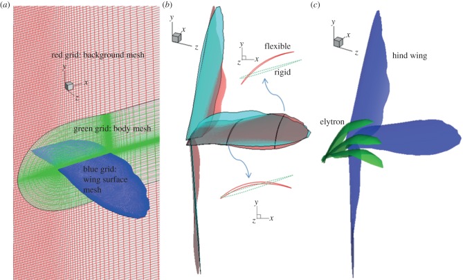
The morphologies of the hind wing and the elytron were measured in order to rebuild realistic wing models used in the simulations. Then, two block structure grids were created: one is the background mesh which covers the fluid domain in the simulation, the other one is a body-fitted mesh that contains the wing surfaces as shown in figure 2a. The no-slip boundary condition was applied on the wing surface; meanwhile the far field condition was imposed on the outer surface of the background mesh.
Figure 2.
(a) Structured grid for Chimera mesh, (b) difference between rigid (skyblue) and flexible (red) hind wing models at typical time steps during downstroke and (c) kinematics of elytron and hind wing used in the simulation. (Online version in colour.)
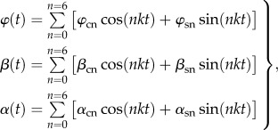
The numerical simulation was conducted in a standard air condition in which the reference velocity (forward velocity) and reference length (chord length) were 1.5 m s−1 and 1.55 cm, respectively. Hence, the non-dimensional parameters of the Reynolds number (Re) and reduced frequency (k) were around 1500 and 1.25, respectively. The flapping motion of the wing was described by the flapping angle, the AOA and the deviation angle while the orientation of the motion was decided by the stroke plane. The time variation of these three angles was digitally extracted from the experimental study, and the approximate function with time was then constructed for each angle by the following equation:
 |
2.1 |
where  , β(t) and α(t) are the flapping angle, the deviation angle and the AOA, respectively. They are approximated by sixth order series in order to match the experimental data well. The coefficients of
  are determined by solving the approximate matrix equation. In the case of the elytron, the deviation angle is too small to be ignored, thus its motion is expressed through two angles: the flapping angle and the AOA.
2.2.3. Wing flexibility and wing interaction
First, the aerodynamic performance of the flexibility of the hind wing was investigated through the following three models. The first model is the rigid wing in which the AOA along the spanwise direction was fixed as a measured value at r/R = 0.4. Here, r is the distance from the wing root to a reference point, meanwhile R is the hind wing's length in the spanwise direction, measured from the wing root to the wing tip, namely, the AOA of all points on the wing at each time step are equal to the measured AOA at r/R = 0.4 at that time step. In other words, AOA is not spatially varied in the rigid wing model. The second model is a twisting wing in which the AOA was varied along the spanwise direction, namely the AOA becomes the function of time and space. The third model is a flexible wing in which camber variation was added compared with the twisting wing. So, both AOA and camber are functions of time and space. Hence, the roles of spanwise twisting and camber variation in aerodynamic performance in beetle flight are expected to be clarified throughout the comparisons of these wing models. The linear variation of the AOA along the spanwise direction versus time are approximated by sixth order series, which is similar to equation (2.1). Then, the variation of the AOA was automatically applied to each point of the wing surface at each time step in the simulation of the twisting wing. Similarly, the time and spatial variation of the camber was also rebuilt as an approximate function, which is applied to each point on wing surface at each time step in the simulation of the flexible wing. Differences in the wing morphologies of the flexible and the rigid wings are represented at typical time steps: t/T = 0, 0.25 and 0.5 which are corresponding to beginning, middle and end positions of the downstroke as shown in figure 2b.
Second, the simulation of the interaction between the elytron and the hind wing was conducted in order to explore the aerodynamic performance of the elytron. The wing interaction between both sides and wing–body interaction in hovering hawkmoths was studied in Aono et al. [30,31], which showed that the difference in the force on left and right wing is ignored owing to symmetric flapping; also, the force generated by the body is much smaller than that by the wing. The interaction between the left and the right wing is expected to be significant only in a small insect at low Reynolds number when the positions of the two wings are closed enough [32]. The beetle is an insect which has a large body and the gap between two wings is quite large, hence the effect of the interaction is estimated to be small. Thus, in this work, we just analysed the interaction between the elytron and the hind wing on one side of the beetle. Interaction simulation requires three blocks of structure grid: one body-fitted mesh is for the elytron, the other is for the hind wing and the background mesh is for the rest. Two wings were controlled to flap simultaneously. The hind wing was a flexible wing while the elytron was a rigid wing, where no twist or camber was considered. The wing positions and shapes at the typical time steps are shown in figure 2c.
2.2.4. Evaluation of force and validation of method
The total aerodynamic force was calculated from the pressure and the shear stress on the wing surface, which are obtained from the solution of the Navier–Stokes equation. Between them, the pressure is a critical factor in evaluating the force in flapping motion. Hence, vortices, the pressure contour around the wing and the pressure coefficient on the wing surface were usually extracted for the quantitative analysis of the aerodynamic performance. The vortices could describe rotational flow structures and a considerable pressure drop normally occurs near their core region. Here, the Q-criterion is chosen among local vortex-identification criteria. Hunt et al. [33] named Q after the second invariant of velocity gradient tensor ∇u, which is calculated by
| 2.2 |
where Ωij = 1/2(∂ui/∂xj − ∂uj/∂xi) and Sij = 1/2(∂ui/∂xj + ∂uj/∂xi). Namely, Q is the balance between the rotational rate ||Ω||2 and the strain rate ||S||2. Thus, iso-surfaces of positive Q indicate areas where the strength of rotation overcomes that of the strain. The pressure coefficient (CP) along a chord line is plotted in order to show differences of pressure on top and bottom surfaces. It is defined as
| 2.3 |
where P is the pressure at a reference point. P∞, ρ∞, and V∞ are pressure, fluid density and velocity under free-stream conditions. Total aerodynamic force was resolved to horizontal force, vertical force and side force in the x, y, and z directions, respectively, in a global fixed coordinate (figure 2). The side forces are cancelled out from left and right side wings owing to symmetry in free-forward flight. The free-stream velocity is parallel to the x direction, hence lift is the vertical force and thrust is the negative horizontal force. The aerodynamic torque (T) in each direction of the flapping motion was also calculated by the sum of the cross product of the force and the position vector from the wing root to each cell centre located on the wing surface as follows:
| 2.4 |
where Fi and ri are force and position vectors at each cell. Then, the aerodynamic power was calculated by the scalar products of the angular velocity and the aerodynamic torque of the wing.
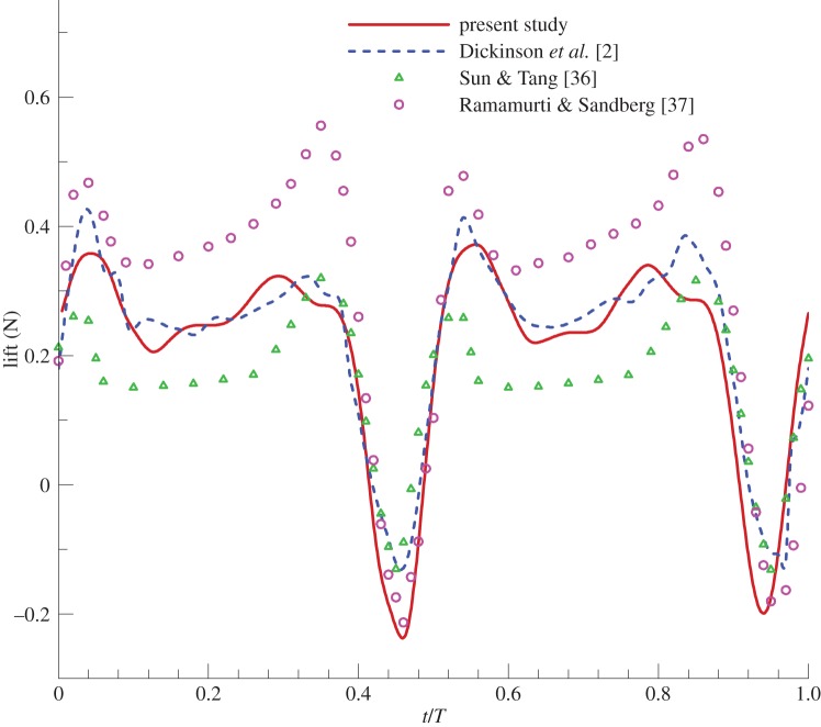
The accuracy of our flow solver in analysing a flapping wing was validated in previous works [34,35]. Moreover, we performed a simulation of a fruitfly model during hovering as the benchmark for the three-dimensional flapping simulation. The flapping kinematics were chosen from the experimental model described in Dickinson et al. [2]. Then, the lifts from our results were compared with the experimental results in Dickinson et al. [2] and other numerical simulation results [36,37]. Figure 3 shows that our results show good agreement with the previous data.
Figure 3.
Benchmarking of three-dimensional flapping simulation. (Online version in colour.)
The convergence solution was obtained when the dependence of the aerodynamic forces on the grid and time was minimized. Two body meshes were used, grid 1 (260 × 40 × 150) and grid 2 (350 × 50 × 180), around the wing section in chordwise, normal and spanwise directions. The difference of forces was less than 2.8 per cent between them. Hence, grid 1 was used to test the effect of the number of time steps. The numbers of the time step in a cycle were 100, 200 and 300 for case 1, 2 and 3, respectively. The difference in force was less than 5 per cent between case 1 and case 2, and less than 3 per cent between case 2 and case 3. Therefore, we chose grid 1 and case 2 for the present study.
3. Result
3.1. Wing kinematics and morphology
The wing morphology was obtained from the experimental measurement. The lengths of the hind wing and elytron were found to be around 48.20 ± 1.38 and 24.14 ± 1.25 mm, respectively. The mean chord length of the hind wing and the elytron were approximately 15.02 ± 0.21 and 14.00 ± 0.38 mm. Hence, the sizes of the hind wing and the elytron were set to 50 × 15 and 25 × 14 mm, respectively, when the grid system of both wings was generated.
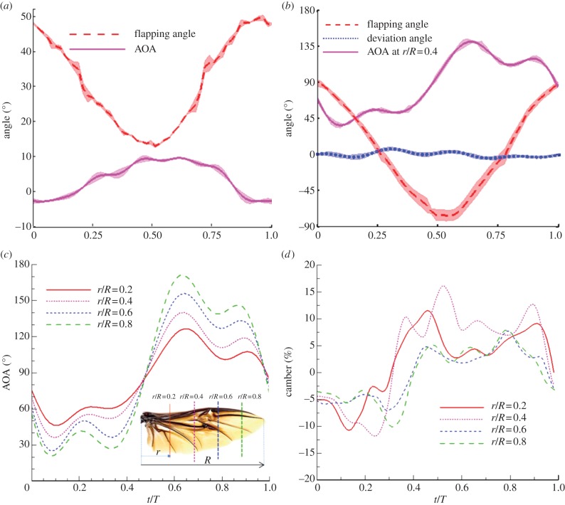
The kinematics of the elytron is shown in figure 4a. Downstroke is the period from 0 to 0.5 non-dimensional time, t/T when the wing tip starts to move from the top position to the bottom position, where T is total period. Meanwhile, upstroke is the period from 0.5 to 1 t/T. Hence, the middle positions of downstroke and upstroke are 0.25 and 0.75 t/T, respectively. There were 53 frames for a single stroke, which means that the frequency (f) was 37.7 ± 0.3 Hz. The body angle is almost zero degrees with respect to the horizontal plane. The free-forward velocity of the beetle was recorded at 1.5 m s−1 based on the tracking body position with the frame at each time step. The stroke angle and the stroke amplitude of the elytron are 78 ± 4.6° and 32 ± 4.4°, respectively. The AOA varies from −5° to 15°. Regarding the hind wing, figure 4b–d shows the wing kinematics as well as the variation of the AOA and the camber deformation along the spanwise direction at r/R = 0.2, 0.4, 0.6 and 0.8. The stroke angle of the hind wing was 72 ± 2.3° during free-forward flight. The stroke amplitude of the hind wing was recorded in a range from 160° to 170° (averaging 164.4 ± 5.6°). The deviation angle was less than 10°. The variation of the AOA showed that the hind wing twisted dramatically during the translational phase (0.1 ≤ t/T ≤ 0.4 and 0.6 ≤ t/T ≤ 0.9) in downstroke and in upstroke, respectively. In the transition phase (0.4 ≤ t/T ≤ 0.6 and 0.9 ≤ t/T ≤ 1.1), the AOA varied largely towards the wing tip. For example, it varied from 46° to 126° and from 21° to 171° at r/R = 0.2 and 0.8, respectively. In addition, the camber variation at each section of the hind wing during the flapping stroke was determined; the maximum positive camber was recorded at around +16% during the downstroke, while the negative camber was −12% during the upstroke [23].
Figure 4.
Kinematics of (a) elytron and (b) hind wing, (c) angle of attack and (d) camber deformation of the hind wing at different sections along the spanwise direction. r is distance from wing root to reference point, meanwhile R is length from wing root to wing tip, in (c). (Online version in colour.)
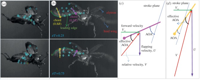
The twist angle is defined as the difference of the AOA between r/R = 0.8 and 0.2. During the flapping cycle, the AOA of the hind wing shows approximately linear decrement in the downstroke and linear increment in the upstroke along the spanwise direction as shown in figure 4c. Thus, the twist angle was negative during the downstroke and positive during the upstroke. For instance, the twist angle was −25° and +35° at the middle positions of the downstroke (t/T = 0.25) and the upstroke (t/T = 0.75), respectively. Figure 5a,b shows the snapshots of wing kinematic and also represents the difference in the orientation of the chord line at r/R = 0.2 and 0.8. The AOA was defined as the angle between the chord line and the stroke plane; meanwhile, the effective AOA is the angle between the chord line and the relative velocity (V), which is the resultant vector of the forward velocity (V∞) and the local flapping velocity (U = ωr). For example, at t/T = 0.25, the AOA is 60 and 35 on sections r/R = 0.2 and 0.8, respectively. The free-stream velocity is 1.5 m s−1, whereas the local flapping velocities are approximately 3 and 12 m s−1 on these sections. Thus, the effective AOA values are approximately 45° and 38° on these sections. Similarly, the effective AOA values are approximately 25° and 12° on sections r/R = 0.2 and 0.8 at the middle position during the upstroke (t/T = 0.75). Consequently, the difference in the effective AOA between r/R = 0.2 and 0.8 becomes smaller than that in the AOA as shown in figure 5c,d because the beetle instinctively changes its wing twist in order to improve the efficiency of its flight.
Figure 5.
Snapshots of the kinematics from (a) side view camera and (b) front view camera. A difference in orientation of chord line at r/R = 0.2 (pink line) and r/R = 0.8 (yellow line) is clearly shown in (b). Correspondingly, AOA and effective AOA are defined at r/R = 0.2 and r/R = 0.8 in (c) and (d), respectively, at the middle position of the downstroke (t/T = 0.25). (Online version in colour.)
3.2. Aerodynamic performance of a flexible hind wing
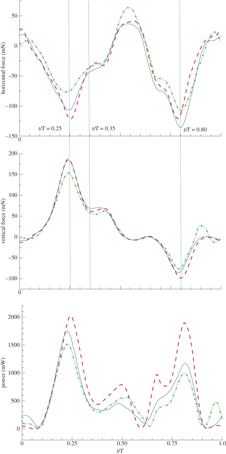
The aerodynamic forces and power required for the flapping motion of three hind wing models are shown in figure 6. The stroke plane angle was 72° with respect to the horizontal plane, which indicates that the hind wing flapped with nearly a vertical stroke; therefore, positive vertical force was typically created during the downstroke and negative force was formed during the upstroke. The magnitude of the instantaneous vertical force of the twisting wing was smaller than that of the rigid wing, as clearly shown in the middle position of the stroke when the twist angle of the hind wing was largest. The instantaneous vertical force of a flexible wing with camber variation was similar to that of the rigid wing during the downstroke; however, it was smaller during the upstroke. Thrust was produced during both strokes owing to the large variation of the AOA. The twisting wing created less thrust than the other models. The thrust created from the flexible wing was similar to that of the rigid wing during the downstroke, while it was largest during the upstroke. The required power for the translational phase (0.1 ≤ t/T ≤ 0.4 and 0.6 ≤ t/T ≤ 0.9) was much higher than that for the transition period in which the wing rotates (0.4 ≤ t/T ≤ 0.6 and 0.9 ≤ t/T ≤ 1.1).
Figure 6.
Effect of the flexibility of the hind wing on the aerodynamic force. (a-c) Dashed line, rigid wing; solid line with triangle, twisting wing; solid line, flexible wing. (Online version in colour.)
Specifically, the power required in the graph shows that the rigid wing requires more energy for flapping in comparison with the other models. The average values of these parameters are summarized in table 1. The advantage of wing twist and camber variation was clearly shown in the comparison of the power economy, which is defined as the ratio of the total aerodynamic force to the required power. The results indicate that the power economies were 0.054 and 0.071 N W−1 for the rigid and twisting wing, respectively. These values are 35 and 15 per cent lower compared with that of the flexible wing (0.084 N W−1).
Table 1.
Average values of the aerodynamic forces and required power during one cycle of flapping.
| rigid wing | twisting wing | flexible wing | |
|---|---|---|---|
| thrust (mN) | 32.2 | 26.7 | 38.9 |
| vertical force (mN) | 20.9 | 23.7 | 23.5 |
| required power (mW) | 709 | 496 | 535 |
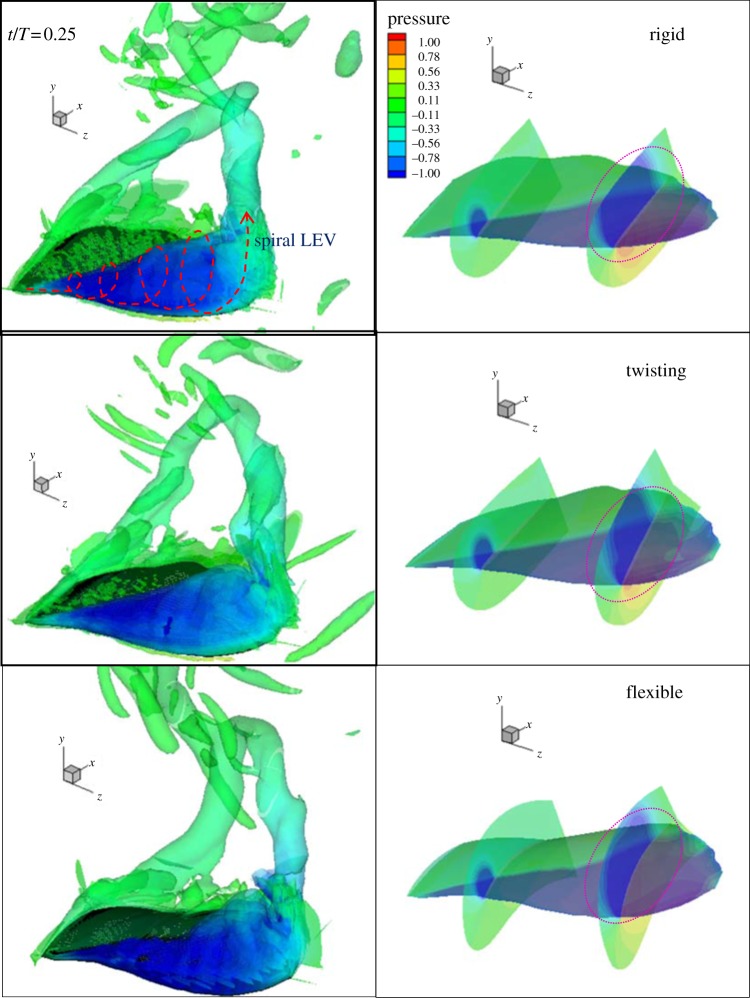
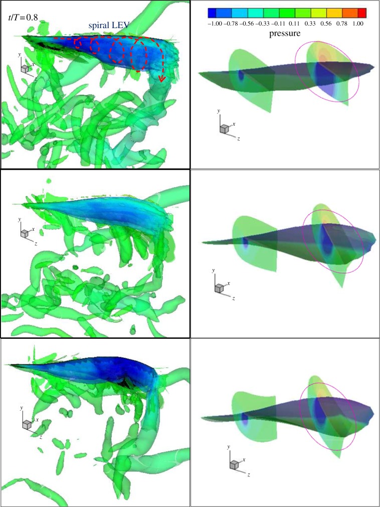
To gain in-depth insight into the performance of all wing models and for the comparisons among them, the vortex and pressure around the wing must be analysed. First, the aerodynamic performance at the middle position of the downstroke, where the difference in the instant forces and power required among these wing models is most significant, was explored. Figure 7 shows the iso-surfaces of the Q-criterion and pressure distribution on the hind wing in the rigid (top) and the twisting (middle) and the flexible (bottom) cases at t/T = 0.25. The iso-surface of the Q-criterion indicates the size of LEV and it is coloured by the pressure magnitude in the figures. Corresponding to the vortices, the pressure distributions on the wing surface as well as on two cross-sections (r/R = 0.3 and 0.75) are depicted in the right column. In general, the vortex aspects in the three cases were quite similar. However, vortex magnitudes differed. At the middle position of the downstroke, the downward translational velocity of the hind wing reached its maximum value and the spiral LEV occurred on the top surface of the wing, and the spiral LEV near the wing tip was inflected to form the tip vortex. Also, the root vortex was connected to the tip vortex and round vortices formed. In a comparison of the colour, the negative pressure in the spiral LEV near the wing tip in the case of the twisting wing was smaller than that of the rigid wing. This can be explained by decrease in the effective AOA towards the wing tip; at r/R = 0.8, it was 38° for the twisting wing and 60° for the rigid wing. The instantaneous positive camber enhanced the strength of the spiral LEV in the flexible wing model. Consequently, the horizontal and vertical forces of the flexible wing are more similar to those of the rigid wing than to those of a twisting wing, as shown in figure 6. The camber apparently improves the instant value of the lift as well as the thrust of the flexible wing compared with the twisting wing.
Figure 7.
Iso-surfaces of Q-criterion (left) and the pressure (right) distribution on rigid, twisting and flexible wings at t/T = 0.25. The iso-surfaces of Q-criterion indicate the size of LEV, and the pressure contour shows high and low pressure zones on surface and vicinity of wing.
The negative pressure (blue) distribution indicated the locations as well as the strength levels of the vortices. On the top surface of the hind wing, the negative pressure region was confined to the leading edge near the wing root and was extended along the chordwise direction near the wing tip; this phenomenon is caused by the spiral LEV. Negative pressure on the cross-sections also shows the strength of the LEV in the vicinity of the top surface of the hind wing, while positive pressure (red) was observed on the bottom surface of the hind wing owing to its downward translational motion. Especially at r/R = 0.75, the strength of the LEV for the three models can be distinguished by the magnitude of the pressure. A clear difference is noted in the size of the LEV between the rigid and twisting wings. The LEV detached and its core moved up and away from the top surface in the rigid wing. On the other hand, it attached easily onto the top surface in the case of the flexible wing owing to its concave shape.
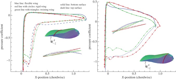
In a more detailed quantitative comparison, the pressure coefficient at two sections was plotted, as shown in figure 8. The strength of the LEV can be seen through the large negative pressure coefficient on the top surface of the hind wing. In the section with r/R = 0.3, the pressure coefficient dropped sharply to a negative value near the leading edge and then recovered quickly, remaining constant towards the trailing edge. Meanwhile, it recovered gradually towards the trailing edge in the section with r/R = 0.75. Again, this phenomenon was caused by the spiral LEV: concentrated on a small area near the wing root and spreading over the wing area near the wing tip. The difference in the positive pressure coefficient on the bottom surface among these wing models also denotes the effects of the camber factor and twist. The difference in the positive pressure in the three models was minor near the wing root when the local flapping velocity was small. The difference became significant near the wing tip; with the twist angle, the chord line was well aligned with the relative velocity and a low amount of positive pressure occurred on the bottom surface in the twisting wing, whereas the positive camber strengthened the positive pressure from the middle position of the chord line towards the trailing edge in the flexible wing.
Figure 8.
Pressure coefficient of the three wing models at (a) r/R = 0.3 and (b) r/R = 0.75 at the middle position of the downstroke (t/T = 0.25); the subfigures show the cross section of the three models and location on the hind wing. Blue, red and green lines indicate flexible, rigid and twisting wings, while solid and dashed lines show pressure coefficient values on bottom and top surfaces, respectively. (Online version in colour.)
Similarly, figure 9 shows the iso-surfaces of Q-criterion and pressure distribution on the three wing models with t/T equal to 0.8, when the wing passed through the middle position of the upstroke. An unstable vortex region appears below the bottom surface of the wing. This was considered to result from the rapid wing rotational motion during the transition period from the downstroke to the upstroke. A new strong spiral LEV is generated on the bottom surface in the three wing models when the wing rapidly moves in the upward direction. The negative pressure area on the section with r/R = 0.75 visually showed the strength of the spiral LEV. At r/R = 0.8, the effective AOA was 12° for the twisting wing and 40° for the rigid wing. Hence, the strength of the spiral LEV on the wing surface in the twisting wing was much smaller than that in the rigid wing. The instant negative camber strengthens the spiral LEV in the flexible wing model. As a result, the rigid wing creates instant negative vertical force that is larger than that of the other wings, as shown in figure 6. The negative camber made the flexible wing produce the largest thrust. In terms of energy consumption, the rigid wing required a considerable amount of power, whereas the other wings needed less during this period.
Figure 9.
Iso-surfaces of Q-criterion (left) and pressure (right) distribution on the rigid, twisting and flexible wings at t/T = 0.80.
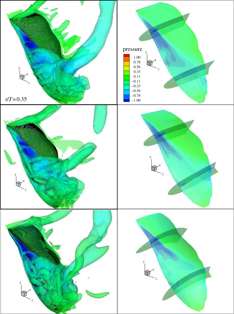
The differences in the force among the three models were apparent at the above two time steps, but they were not during the other time intervals. Therefore, we selected one specific time step (t/T = 0.35) to determine the factors that caused this. When the hind wing passed through the middle position and towards the end position of the downstroke, the spiral LEV near the wing tip fully detached from the top surface and was shed into the wake in the downstream. At t/T = 0.35, an unstable vortex was observed near the wing tip, showing a complicated structure of the vortices with the combination of the spiral LEV and the tip vortex, as shown in figure 10. The ring of the tip vortex broke down in the downstream in the case of the twisting wing owing to its low strength. Corresponding to the pressure distribution, the area shown in blue, which exists only near the wing root, indicates that strong negative pressure dominates. In other words, the spiral LEV is still attached to the wing surface near the wing root. On the other hand, the area in blue is diluted to green in the detaching vortex area near the wing tip. At this moment (t/T = 0.35), the forces and required power are small and the effect of the twist and the camber is trivial. In general, the effect of the twist and camber is not significant in the period when the spiral LEV is detached from the wing surface.
Figure 10.
Iso-surfaces of Q-criterion (left) and the pressure (right) distribution on the rigid, twisting and flexible wings at t/T = 0.35.
3.3. Elytron–hind wing interaction considering the flexibility of the hind wing
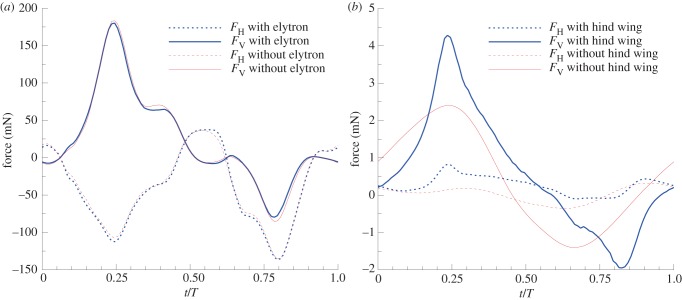
The elytron–hind wing interaction was also studied when the flexible hind wing was considered. In addition, numerical simulation of the elytron only was conducted for comparison purposes. Figure 11 shows the aerodynamic forces acting on the elytron and hind wing with and without interaction. The difference in the force was significant on the elytron, whereas it was minor on the hind wing. This is the typical aerodynamics of the beetle owing to the major difference in the size, materials, and kinematics between the elytron and the hind wing. The instantaneous vertical force on the elytron was increased, especially at the middle position of the stroke, when both wing positions moved closer to each other. In addition, the horizontal force on the elytron also increased owing to the interaction. The large size and high flapping velocity of the hind wing significantly affected the aerodynamics of the elytron, whereas there was no effect in the reverse case.
Figure 11.
Aerodynamic forces on the (a) hind wing and (b) elytron with and without interaction. (Online version in colour.)
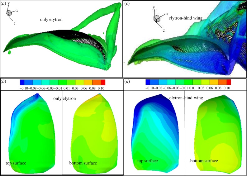
The downward velocity of the hind wing increased with time from the beginning position to the middle position of the downstroke. Hence, the free stream over top surface of the elytron was ‘accelerated’ to move down along the trajectory of the hind wing, while the hind wing flapped down at a high velocity. Therefore, the LEV on the top surface of the elytron was enlarged, a difference in pressure between top and bottom surface of the elytron became significant. Figure 12 shows the difference in the size of the iso-surface of the Q-criterion of the elytron when there was no interaction (figure 12a) and interaction (figure 12c). Correspondingly, figure 12 also demonstrates the pressure difference between top and bottom surfaces in the case of no interaction (figure 12b) and interaction (figure 12d). As a result, the instantaneous vertical force on elytron of the case with interaction increased up to almost three times as compared with that of the case without interaction. Afterwards, the relative positions of the elytron and the hind wing were far apart, and the wing interaction effect then became weaker. Based on our experimental observation, the wing sizes and flapping angles of the hind wing were two and five times these of the elytron. Hence, the magnitude of the forces on the elytron was much smaller than that on the hind wing. Therefore, we explored the forces on the elytron with respect to its weight. The gravity force of the elytron is 0.55 mN, which is quite high owing to its larger density than that of the hind wing. The elytron could not support its own weight by the aerodynamic force generated when the interaction is not considered (0.42 mN). However, the wing interaction enhanced the mean vertical force on the elytron to 0.62 mN, which yielded a 50 per cent improvement. Therefore, its weight was fully supported by itself. The elytron–hind wing interaction also increased the drag on the elytron from 0.025 to 0.23 mN.
Figure 12.
Difference in iso-surfaces of Q-criterion on only (a) elytron and (c) elytron with hind wing. Corresponding, pressure distribution on top and bottom surfaces in (b,d).
4. Discussion
After exploring the basic mechanism of a flapping wing, researchers became more interested in the optimization of the flying mechanism of insect models. They currently focus on wing flexibility, including wing twisting along the spanwise direction and camber variation along the chord-wise direction. The flapping power economy is used in evaluating the performance of the flapping model. The locust flight model was investigated by comparing a full-fidelity wing, a twisting-only wing and a camber-only wing [14]. The highest power economy was achieved in the full-fidelity model. The low efficiency of the momentum transfer in the simplified models was attributable partly to the flow separation at the leading edge. Basically, the high lift of insect flight are typically associated with massive flow separation and a large LEV during flapping [3,38]. However, the high lift is not always required for all flight conditions; hence, the size of the LEV should be controlled to obtain higher efficiency. How the leading edge becomes well aligned with the incoming flow during flight is dependent on wing flexibility. In an experimental study of a dragonfly, the mechanism involved in the foundation of the LEV was observed through a smoke wire visualization method [38]. The role of the AOA for the generation of the LEV was emphasized.
In a steady flow, the stall phenomenon usually occurs when the effective AOA is larger than 15°. Meanwhile, in an unsteady flow, the flow is separated at the leading edge of the wing and then reattaches to the wing surface behind the leading edge along the wing chord direction over 15° of the effective AOA. This phenomenon is called the delayed stall. For the rigid wing, the effective AOA was constant along the spanwise direction, and it was changed in the range from 45° to 60° during the downstroke. Hence, the separation of the flow became massive near the wing tip of the hind wing, where the local angular flapping velocity was high. For the twisting wing, the effective AOA was modulated towards the wing tip in the range from 30° to 40° and the smaller LEV is then generated. Thus, lower power consumption by the smaller LEV is expected for the twisting wing than for the rigid wing.
In our simulation result, the spiral LEV was considered to be the main source of the high unsteady force at the middle position of the stroke in the three wing models. The tendency of the force distribution in these models was similar except for the difference in the magnitude of the instantaneous forces at the middle position of the strokes. Near the wing tip, the strength of the spiral LEV was significantly different between the rigid and twisting wings. The rigid wing generated a stronger spiral LEV than the twisting wing, which yielded higher aerodynamic force on it. In terms of momentum transfer, massive flow separation occurred and a large amount of energy was consumed as vortex activities in the wake. Therefore, a high level of power was needed for lift generation at this moment in the rigid wing. During forward flight, the beetle only needs the mean vertical force to support its weight with a large amount of thrust to fly forward rapidly. This indicates that the average vertical force during one stroke of flapping is much more important than the instantaneous force. The positive camber in a flexible wing not only generates high lift, but also enhances the thrust as compared with the rigid wing, as shown in figure 6. The aerodynamic force of the rigid wing represents inefficient kinematics for the forward flight because the high positive vertical force during the downstroke is almost cancelled out by the high negative force during the upstroke. Meanwhile, the mean vertical force was the lowest among the three models. Furthermore, it takes highest power from the muscle of the beetle for high instantaneous force during both strokes. A natural flyer will apply other efficient wing kinematics instead of a rigid wing. By varying the AOA along the spanwise direction and the camber along the chord-wise direction, the leading edge of the hind wing can align suitably to the incoming flow direction near the wing tip; therefore, the flow can reattach to the wing surface well. This is useful during the upstroke when the negative vertical force needs to be minimized. The average vertical force of the flexible wing was improved by 13 per cent compared with that of a rigid wing, and it was close to the gravity force of the beetle, which is in the range of 45–50 mN. In addition, the flexible wing can reduce the required power by 25 per cent with respect to the rigid wing. This highlights the critical role of the effective AOA as well as the camber in optimizing the flapping mechanism, as previously reported [38]. It was demonstrated from our simulations that the aerodynamic power efficiency of beetles appears to derive from their ability of reduce the flow separation and the associated loss of energy while maintaining the flight function.
Hitherto, fewer reports on the elytra and their role in aerodynamic performance can be found in the literature. Their main objective is apparently a protective function of the hind wings in resting state. The coupling force owing to the interlocking mechanism for opening and closing elytra may be as high as 160 times the gravity force of its own bodyweight [39]. The high force allows the beetle to safely penetrate soil, wood and hard material and to protect a thin and highly flexible hind wing that shows extraordinary aerodynamic performance. Other previous studies focus on geometry and mechanical properties of the elytra: hardness and modulus of fresh cybister elytra are 0.31 and 6.13 GPa, respectively, and the difference of ultimate stresses in transverse and longitudinal directions has been reported [40]. The elastic properties of the wings are determined by resilin (a rubber-like protein) distribution inside the vein system [41]. The mechanisms of folding and unfolding of the hind wing are strongly interactive movements of elytra, namely as autapomorphic character states of Coleoptera [42]. These results provide deep insights into the design mechanism and structure for future flight vehicles by mimicking bio-structure. Meanwhile, there are few comprehensive reports for the role of the elytron in aerodynamic performance, which is the critical factor for flight vehicles. One of the main contributions of our work is findings about the role of the elytron in aerodynamic performance while considering the interaction of the hind wing.
Owing to the large difference in the size and the flapping angle between the elytron and the hind wing, the interaction effect was clearly observed only on the elytron. The wing interaction not only significantly increases the vertical force on the elytron, but also maintains the aerodynamic performance of the hind wing. Flapping in phase with the hind wing, the elytron creates enough vertical force to support its weight. Furthermore, during the motion in phase, the elytron can avoid blocking the flow stream or having other negative aerodynamic effects on the hind wing during free-forward flight. Consequently, when the effects of wing flexibility and interaction are combined, the vertical force from both wings (48.4 mN) becomes larger than the gravity force of the beetle (47.5 mN).
5. Conclusion
The role of the flexibility of the hind wing and elytra–hind wings interaction of a beetle during free-forward flight was studied through a numerical simulation. Preliminary experimental measurements determined a large twist angle along the spanwise direction and great variation of the camber during flapping. These factors reduce massive flow separations on the leading edge, yielding a small amount of instantaneous negative vertical force during the upstroke in a flexible wing model. Therefore, a significant improvement in the mean values of the lift and thrust was achieved; moreover, less power was required in the flexible wing model. As a result, the advantage of the flexibility of the wing was clearly revealed owing to the enhancement of the power economy. The elytron–hind wing interaction provided an improvement in the aerodynamic forces mainly acting on the elytron, and the total lift for wing flexibility and interaction is then enough to support the weight of the beetle during free-forward flight.
Acknowledgements
This research was supported by the Basic Science Research Programme through the National Research Foundation of Korea (NRF) financially supported by the Ministry of Education, Science and Technology (2010–0015174), and the New and Renewable Energy R&D programme of the Korea Institute of Energy Technology Evaluation and Planning (KETEP) grant financially supported by the Korea government Ministry of Knowledge Economy (No. 20113020070010). PLSI supercomputing resources of Korea Institute of Science and Technology Information supported our numerical simulations.
References
- 1.Sane SP. 2003. The aerodynamics of insect flight. J. Exp. Biol. 206, 4191–4208 10.1242/jeb.00663 (doi:10.1242/jeb.00663) [DOI] [PubMed] [Google Scholar]
- 2.Dickinson MH, Lehmann F-O, Sane SP. 1999. Wing rotation and the aerodynamic basis of insect flight. Science 284, 1954–1960 10.1126/science.284.5422.1954 (doi:10.1126/science.284.5422.1954) [DOI] [PubMed] [Google Scholar]
- 3.Ellington CP, Berg Cvd, Willmott AP, Thomas ALR. 1996. Leading edge vortices in insect flight. Nature 384, 626–630 10.1038/384626a0 (doi:10.1038/384626a0) [DOI] [Google Scholar]
- 4.Wang JK, Sun M. 2005. A computational study of the aerodynamics and forewing-hindwing interaction of a model dragonfly in forward flight. J. Exp. Biol. 208, 3785–3804 10.1242/jeb.01852 (doi:10.1242/jeb.01852) [DOI] [PubMed] [Google Scholar]
- 5.Wang ZJ, Russell D. 2007. Effect of forewing and hindwing interactions on aerodynamic forces and power in hovering dragonfly flight. Phys. Rev. Lett. 99, 148101. 10.1103/PhysRevLett.99.148101 (doi:10.1103/PhysRevLett.99.148101) [DOI] [PubMed] [Google Scholar]
- 6.Lan SL, Sun M. 2001. Aerodynamic force and flow structures of two airfoils in flapping motions. Acta Mech. Sin. 17, 310–331 10.1007/BF02487459 (doi:10.1007/BF02487459) [DOI] [Google Scholar]
- 7.Walker SM, Thomas ALR, Taylor GK. 2009. Deformable wing kinematics in the desert locust: how and why do camber, twist and topography vary through the stroke? J. R. Soc. Interface 6, 735–747 10.1098/rsif.2008.0435 (doi:10.1098/rsif.2008.0435) [DOI] [PMC free article] [PubMed] [Google Scholar]
- 8.Walker SM, Thomas ALR, Taylor GK. 2010. Deformable wing kinematics in free-flying hoverflies. J. R. Soc. Interface 7, 131–142 10.1098/rsif.2009.0120 (doi:10.1098/rsif.2009.0120) [DOI] [PMC free article] [PubMed] [Google Scholar]
- 9.Dong H, Koehler C, Liang Z, Wan H, Gaston Z. 2010. An Integrated Analysis of a Dragonfly in Free Flight. In 28th AIAA Applied Aerodynamics Conf., Chicago, IL: Chicago, IL: IAAA. [Google Scholar]
- 10.Vanella M, Fitzgerald T, Preidikman S, Balaras E, Balachandran B. 2009. Influence of flexibility on the aerodynamic performance of a hovering wing. J. Exp. Biol. 212, 95–105 10.1242/jeb.016428 (doi:10.1242/jeb.016428) [DOI] [PubMed] [Google Scholar]
- 11.Bos FM, Lentink D, Oudheusden BWv, Bijl H. 2008. Influence of wing kinematics on aerodynamic performance in hovering insect flight. J. Fluid Mech. 594, 341–368 10.1017/S0022112007009172 (doi:10.1017/S0022112007009172) [DOI] [Google Scholar]
- 12.Zhao L, Huang Q, Deng X, Sane SP. 2009. Aerodynamic effects of flexibility in flapping wings. J. R. Soc. Interface 7, 485–497 10.1098/rsif.2009.0200 (doi:10.1098/rsif.2009.0200) [DOI] [PMC free article] [PubMed] [Google Scholar]
- 13.Heathcote S, Wang Z, Gursul I. 2008. Effect of spanwise flexibility on flapping wing propulsion. J. Fluids Struct. 24, 183–199 10.1016/j.jfluidstructs.2007.08.003 (doi:10.1016/j.jfluidstructs.2007.08.003) [DOI] [Google Scholar]
- 14.Young J, Walker SM, Bomphrey RJ, Taylor GK, Thomas ALR. 2009. Details of insect wing design and deformation enhance aerodynamic function and flight efficiency. Science 325, 1549–1552 10.1126/science.1175928 (doi:10.1126/science.1175928) [DOI] [PubMed] [Google Scholar]
- 15.Fitzgerald T, Valdez M, Vanella M, Balaras E, Balachandran B. 2011. Flexible flapping systems: computational investigations into fluid–structure interactions. Aeronaut. J. 115, 593–604 [Google Scholar]
- 16.Shoele K. 2011. Flow interaction with highly flexible structures In structural engineering, p. 222 San Diego, CA: University of California [Google Scholar]
- 17.Nakata T, Liu H. 2011. Aerodynamic performance of a hovering hawkmoth with flexible wings: a computational approach. Proc. R. Soc. B 279, 722–731 10.1098/rspb.2011.1023 (doi:10.1098/rspb.2011.1023) [DOI] [PMC free article] [PubMed] [Google Scholar]
- 18.Frantsevich L, Dai Z, Wang WY, Zhang Y. 2005. Geometry of elytra opening and closing in some beetles (Coleoptera, Polyphaga). J. Exp. Biol. 208, 3145–3158 10.1242/jeb.01753 (doi:10.1242/jeb.01753) [DOI] [PubMed] [Google Scholar]
- 19.Frantsevich L. 2012. Double rotation of the opening (closing) elytra in beetles (Coleoptera). J. Insect Physiol. 58, 24–34 10.1016/j.jinsphys.2011.09.010 (doi:10.1016/j.jinsphys.2011.09.010) [DOI] [PubMed] [Google Scholar]
- 20.Frantsevich L. 2010. Indirect closing of the elytra in a cockchafer, Melolontha hippocastani F. (Coleoptera:Scarabaeidae). J. Exp. Biol. 213, 1836–1843 10.1242/jeb.041350 (doi:10.1242/jeb.041350) [DOI] [PubMed] [Google Scholar]
- 21.Burton AJ, Sandeman DC. 1961. The lift provided by elytra of the rhiniceros beetle, Oryctes boas fabr. South Afr. J. Sci. 57, 107–109 [Google Scholar]
- 22.Sitorus PE, Park HC, Byun D, Goo NS, Han CH. 2010. The role of elytra in beetle flight: I. Generation of quasi-static aerodynamic forces. J. Bionic Eng. 7, 354–363 10.1016/S1672-6529(10)60267-3 (doi:10.1016/S1672-6529(10)60267-3) [DOI] [Google Scholar]
- 23.Truong TV, Le TQ, Byun D, Park HC, Kim M. 2012. Flexible wing kinematics of a free-flying beetle (rhinoceros beetle trypoxylus dichotomus). J. Bionic Eng. 9, 177–184 10.1016/S1672-6529(11)60113-3 (doi:10.1016/S1672-6529(11)60113-3) [DOI] [Google Scholar]
- 24.Park SH. 2003. Prediction methods of dynamic stability derivatives using the navier–stokes equations. PhD thesis, Korea Advanced Institute of Science and Technology, Korea [Google Scholar]
- 25.Park SH, Kwon JH. 2003. On the dissipation mechanism of Godunov-type schemes. J. Comput. Phys. 188, 524–542 10.1016/S0021-9991(03)00191-8 (doi:10.1016/S0021-9991(03)00191-8) [DOI] [Google Scholar]
- 26.Park SH, Lee JE, Kwon JH. 2006. Preconditioned HLLE method for flows at all Mach numbers. AIAA J. 44, 2645–2653 10.2514/1.12176 (doi:10.2514/1.12176) [DOI] [Google Scholar]
- 27.Park SH, Kwon JH. 2004. Implementation of k–ω turbulence models in an implicit multigrid method. AIAA J. 42, 1348–1357 10.2514/1.2461 (doi:10.2514/1.2461) [DOI] [Google Scholar]
- 28.Cho KW, Kwon JH, Lee S. 1998. Development of a fully systemized chimera methodology for steady/unsteady problems. J. Aircraft 36, 973–980 10.2514/2.2538 (doi:10.2514/2.2538) [DOI] [Google Scholar]
- 29.Sa JH, Kim JW, Park SH, Park JS, Jung SN, Yu YH. 2009. KFLOW results of airloads on HART-II rotor blades with prescribed blade deformation. Int. J. Aeronaut. Space Sci. 10, 52–62 10.5139/IJASS.2009.10.2.052 (doi:10.5139/IJASS.2009.10.2.052) [DOI] [Google Scholar]
- 30.Aono H, Liang F, Liu H. 2008. Near- and far-field aerodynamics in insect hovering flight: an integrated computational study. J. Exp. Biol. 211, 239–257 10.1242/jeb.008649 (doi:10.1242/jeb.008649) [DOI] [PubMed] [Google Scholar]
- 31.Aono H, Shyy W, Liu H. 2009. Near wake vortex dynamics of a hovering hawkmoth. Acta Mech. Sin. 25, 23–36 10.1007/s10409-008-0210-x (doi:10.1007/s10409-008-0210-x) [DOI] [Google Scholar]
- 32.Lehmann F-O, Sane SP, Dickinson MH. 2005. The aerodynamic effects of wing–wing interaction in flapping insect wings. J. Exp. Biol. 208, 3075–3092 10.1242/jeb.01744 (doi:10.1242/jeb.01744) [DOI] [PubMed] [Google Scholar]
- 33.Hunt JCR, Wray AA, Moin P. 1988. Eddies, streams, and convergence zones in turbulent flows, in Center for Turbulence Research Report CTR-S88, pp. 193–208
- 34.Le TQ, Han IS, Park SH, Ko JH. 2012. High power extracted from flexible flapping tidal generator In Asian wave and tidal energy Conference, Jeju Islan, Korea, 27–30 November 2012. Beijing, China: NEEC [Google Scholar]
- 35.Le TQ, Ko JH, Byun D, Park SH, Park HC. 2010. Effect of chord flexure on aerodynamic performance of a flapping wing. J. Bionic Eng. 7, 87–94 10.1016/S1672-6529(09)60196-7 (doi:10.1016/S1672-6529(09)60196-7) [DOI] [Google Scholar]
- 36.Sun M, Tang J. 2002. Unsteady aerodynamic force generation by a model fruit fly wing in flapping motion. J. Exp. Biol. 205, 55–70 [DOI] [PubMed] [Google Scholar]
- 37.Ramamurti R, Sandberg WC. 2002. A three-dimensional computational study of aerodynamic mechanisms of insect flight. J. Exp. Biol. 205, 1507–1518 [DOI] [PubMed] [Google Scholar]
- 38.Thomas ALR, Taylor GK, Srygley RB, Nudds RL, Bomphrey RJ. 2004. Dragonfly flight: free-flight and tethered flow visualizations reveal a diverse array of unsteady lift-generating mechanisms, controlled primarily via angle of attack. J. Exp. Biol. 207, 4299–4323 10.1242/jeb.01262 (doi:10.1242/jeb.01262) [DOI] [PubMed] [Google Scholar]
- 39.Dai ZD, Zhang YF, Liang XC, Sun JR. 2008. Coupling between elytra of some beetles: mechanism, forces and effect of surface texture. Sci. China Ser. C Life Sci. 51, 894–901 10.1007/s11427-008-0124-7 (doi:10.1007/s11427-008-0124-7) [DOI] [PubMed] [Google Scholar]
- 40.Yang Z, Dai Z, Guo C. 2010. Morphology and mechanical properties of Cybister elytra. Chin. Sci. Bull. 55, 771–776 10.1007/s11434-009-0363-4 (doi:10.1007/s11434-009-0363-4) [DOI] [Google Scholar]
- 41.Haa F, Gorb S, Blickhan R. 2000. The function of resilin in beetle wings. Proc. R. Soc. Lond. B 267, 1375–1381 10.1098/rspb.2000.1153 (doi:10.1098/rspb.2000.1153) [DOI] [PMC free article] [PubMed] [Google Scholar]
- 42.Haas F, Beutel RG. 2001. Wing folding and the functional morphology of the wing base in Coleoptera. Zoology 104, 123–141 10.1078/0944-2006-00017 (doi:10.1078/0944-2006-00017) [DOI] [PubMed] [Google Scholar]


