

Abstract
The European X-ray free-electron laser (XFEL) facility, under construction in the Hamburg region, will provide high-peak brilliance (greater than 1033 photons s−1 mm−2 mrad−2 per 0.1% BW), ultrashort pulses (approx. 10 fs) of X-rays, with a high repetition rate (up to 27 000 pulses s−1) from 2016 onwards. The main features of this exceptional X-ray source, and the instrumentation developments necessary to exploit them fully, for application to a variety of scientific disciplines, are briefly summarized. In the case of structural biology, that has a central role in the scientific case of this new facility, the instruments and ancillary laboratories that are being planned and built within the baseline programme of the European XFEL and by consortia of users are also discussed. It is expected that the unique features of the source and the advanced features of the instrumentation will allow operation modes with more efficient use of sample materials, faster acquisition times, and conditions better approaching feasibility of single molecule imaging.
Keywords: X-ray lasers, free-electron lasers, X-ray instrumentation, structural biology
1. Introduction
The advent of X-ray free-electron lasers, in the past few years, has not only raised hopes of reducing the requirements on size and quality of biological macromolecular crystals, (and has allowed first demonstrations of these ideas in practice [1]), but it has also raised the hope of eliminating the hurdle of crystallization altogether. The purpose of this review is to outline the main features of the European X-ray free-electron laser facility and its planned use for structural biology applications, and to show what it may contribute to the development of the field. In §2, the main parameters of this X-ray source are briefly reviewed, together with a description of the present status and the forthcoming steps of the construction project; the repetition rate and the time structure of the pulse trains, together with the recent developments in the detector area, shall be discussed. The planned instruments and additional facilities for life sciences applications are described in §3; finally, in §4, some ideas about the possible operation modes and their impact on structural biology experiments are discussed.
2. The European X-ray free-electron laser facility
There are at present two operating hard X-ray free-electron lasers worldwide, one in the USA (LCLS, the Linac Coherent Light Source, in Stanford, CA [2]) which delivered the first beam at 0.15 nm in April 2009; and one in Japan (spring-8 angstrom compact laser, the SACLA [3]), operational since June 2011; there are furthermore three projects in the construction phase, one in Switzerland (Swiss FEL) at the Paul Scherrer Institute [4], one in South Korea, at the Pohang Accelerator Laboratory [5] and the European X-ray free-electron laser facility (European XFEL) in the Hamburg region in Germany [6]. All of them target the production of wavelengths of the order or smaller than 0.1 nm, suitable for experiments determining structural properties with atomic resolution. The European XFEL, which has been under construction since January 2009, is powered by a 1.7 km long superconducting linear accelerator, based on the TESLA technology already tested in the soft X-ray FLASH facility at DESY. The adoption of the superconducting technology allows the production of up to 27 000 pulses s−1, to be compared with the typical approximately 100 pulses s−1 of normal-conducting Linac FELs. In table 1, the main design parameters of the European XFEL are compared with those of the two operating facilities.
Table 1.
Basic parameters of the European XFEL in comparison with those of the two operating hard X-rays FEL projects; brilliances are expressed in photons s−1 mrad−2 mm−2 per 0.1%BW.
| facility | LCLS | SACLA | European XFEL (SASE1 undulator) |
|---|---|---|---|
| max. electron energy (GeV) | 14.3 | 8.0 | 17.5 |
| min. photon wavelength (nm) | 0.15 | 0.06 | <0.05 |
| photons per pulse | approximately 1012 | 2×10¹¹ | approximately 1012 |
| peak brilliance | approximately 8×1032 | approximately 1033 | 5×1033 |
| average brilliance | 2×10²¹ | 3×10²⁰ | approximately 1025 |
| pulses per second | 120 | 60 | 27 000 |
| date of first beam | 2009 | 2011 | 2016 |
The time distribution of the 27 000 pulses s−1 is dictated by the properties of the RF system and by the need to limit the cryogenic power requirements. The bunches will be delivered (figure 1) within electron bunch trains, each train 600 µs long, and containing up to 2700 bunches; within the basic 10 Hz repetition rate of the RF system; successive trains are separated by 100 ms, whereas, inside each train, consecutive bunches are spaced by approximately 222 ns, corresponding to an effective repetition rate, during each train, of approximately 4.5 MHz.
Figure 1.
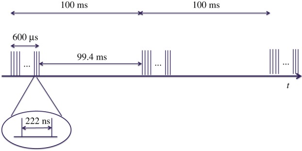
Schematic of the time sequence of both the electron bunches and the X-ray pulses at the European XFEL. (Online version in colour.)
After reaching their final energy at the end of the Linac, electron bunches can be directed in either of two electron beamlines, and pass through long undulators, as schematically illustrated in figure 2. In the undulators, the electron bunches will produce photon pulses by the ‘SASE’ process [7]; the time structure of the photon pulses is a faithful reproduction of the bunch time structure depicted in figure 1. The first beamline contains a hard X-ray undulator (SASE1), generating photons tunable between 8.4 and 25 keV (at 17.5 GeV electron energy: softer X-ray radiation is of course obtained if the electron energy is reduced, according to the γ2 undulator law), and a soft X-ray undulator (SASE3), which can, under some circumstances (see §4), make use of the ‘spent’ beam resulting from saturation of SASE1 to generate soft X-rays in the 0.78–3.1 keV range (at 17.5 GeV). The second beamline (upper branch in figure 2) contains a second hard X-ray undulator (SASE2), identical to SASE1, and two tunnels downstream, initially empty, in which two further undulators can be later located, in future upgrades of the facility. The hard X-ray undulators consist of 35 segments, each 5 m long, with a period of 40 mm; the soft X-ray undulator SASE3 consists of 21 such segments, with a 68 mm period.
Figure 2.
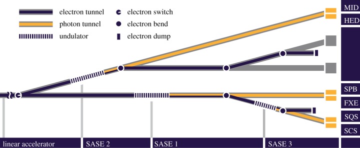
Schematic of the layout of the undulator and photon tunnels and of the instruments at the European XFEL. The linear accelerator is to the left of the figure. The SASE1, SASE2 and SASE3 undulator positions are visible; between the SASE1 and the SASE2 tunnels, the two additional undulator tunnels available for future developments are shown. MID, materials imaging and dynamics; HED, high-energy density matter experiments; SPB, single molecules, clusters and biomolecules; FXE, femtosecond X-ray experiments; SQS, small quantum systems; SCS, spectroscopy and coherent scattering. (Online version in colour.)
In the baseline design for the initial phase of the facility, each of the three installed SASE undulators will feed into two instruments, although, in principle, a third one could be added. Out of the six instruments planned for day one of operation, the most relevant for structural biology is the single particles, biomolecules (SPB) and clusters instrument on SASE1, whereas soft X-ray imaging of larger objects will be done on the SASE3 instruments, soft X-ray coherent scattering/spectroscopy (SCS) and small quantum systems (SQS).
The photons beams produced in the undulators are transported to the experimental hall through long optical transport systems; the SASE1 optical beamline is over 900 m long. The long drift distances ensure reduced optical load on mirrors and crystals and sufficient separation in the 90 m wide experiment hall between instruments fed by different undulators.
Altogether, the linear length of the facility is over 3 km, starting within the DESY site with the electron gun and the injector, and ending with the experiment hall near the town of Schenefeld (figure 3). The facility is completely underground, at a depth varying between 6 and 38 m below ground. The underground civil construction (tunnels, shafts, experiment hall) was completed in the summer of 2013. At present, mass manufacturing of accelerator and undulator components is in progress. The installation of the gun is in progress, and its commissioning started in the last quarter of 2013. The injector will follow, with commissioning starting in early 2015; the Linac components will be installed starting in 2014, with the aim of completing the assembly by the end of 2015. The installation of the undulators and of the X-ray beam transport systems will start in the final quarter of 2014, first with SASE1 and SASE3 and the related systems, and about one year later, by autumn 2015, with SASE2 and the respective beamline. The installation of the hutches, of their infrastructure and safety systems will follow the same sequence, so that SASE1 instruments will be installed starting in late 2015, in order to be ready for commissioning with beam in late 2016, followed by SASE3 and then SASE2.
Figure 3.
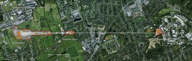
Layout of the European XFEL facility; the path of the underground tunnels is superimposed on the map of the northwest part of Hamburg and of the town of Schenefeld in Schleswig-Holstein. (Online version in colour.)
One of the major challenges in the delivery of the instrumentation for the European XFEL is the handling and the effective use of the very closely spaced pulses of each pulse train, separated by approximately 222 ns. This is a challenge for the optical and beam-transport components (as the SASE photon pulses are of the order of approximately 1 mJ each, during the 600 µs train, the average power of the photon beam is several kW), the diagnostics, the optical lasers for pump-probe experiments and for the detectors, in particular mega-pixel (Mpx) two-dimensional imaging detectors, that should read out and accumulate images at 4.5 MHz rate. An extensive instrumentation R&D programme was therefore launched at an early stage, in cooperation with laboratories all over Europe. Among the three imaging Mpx detector developments, the most promising for structural biology applications is the adaptive gain integrated pixel detector (AGIPD). This detector [8], with 200 × 200 µm2 pixels, can read out and acquire 352 images at 4.5 MHz (corresponding to 352 successive pulses, or even more, if a fast and efficient procedure is adopted to identify and discard, or ‘veto’, non-usable images, such as pulses failing to hit any target molecules). Its dynamic range spans from single photons to 104 photons per pixel per pulse. Preliminary tests performed with the synchrotron facilities Doris and Petra 3 at DESY on a small area prototype confirmed data acquisition at 4.5 MHz and adequate radiation hardness.
3. Instrument and facilities for structural biology at the European X-ray free-electron laser
In the baseline construction programme of the European XFEL, six instruments are foreseen for the initial stage of operation of the facility, two for each undulator. In particular, the SPB instrument, powered by the SASE1 hard X-ray undulator, is directed towards the requirements and the expectations of the structural biology community. In addition to the six baseline instruments, complementary instrumentation and facilities are foreseen through the user consortia programme, launched by the European XFEL in 2011, to solicit the groups of interested users to contribute additional equipment with their own resources. Out of the seven approved user consortia proposals, three originate from the structural biology community and considerably improve the capacity and the potential of the facility for this scientific field.
A detailed description of the SPB instrument can be found in the technical design report issued in August 2013 by Mancuso et al. [9]. Here, we summarize in the basic design parameters and objectives in table 2.
Table 2.
Basic parameters of the SPB instrument at the European XFEL.
| parameter | value (range) | unit |
|---|---|---|
| photon energy | 3–16 | keV |
| pulse energy (max at source) | approximately 1–5 | mJ |
| photons per pulse (max at source) | approximately 1–8 × 10¹² photons | — |
| focal spot size | approximately 0.1 and 1.0 | µm |
| max repetition rate | 10 × 1350 (highest pulse energy) 10 × 2700 (lower pulse energies) |
s−1 |
| pulse duration (range) | few to approximately 100 | fs |
| detector pixel size (AGIPD) | 200 × 200 | µm2 |
| upstream detector | four independent quadrants (4 × 512 × 512 pixels) |
— |
| downstream detector | 2 independent quadrants (2 × 512 × 128 pixels) |
— |
| single-photon sensitivity | yes | — |
| dynamic range (at 12 keV) | >104 | photons |
| detector frame rate | 4.5 | MHz |
| sample–detector distances | approx. 0.13–5 (upstream) approx. 7–12 (downstream) |
m |
| sample delivery options | liquid jet aerosol jet fixed targets |
The basic layout of the optics is shown in figure 4. A four-bounce focusing mirror system is located in the optics hutch, and the achieved approximately 1 µm focus can be transported to the experimental hutch for direct use, or transmitted through to the station contributed by the user consortium serial femtosecond crystallography (SFX) downstream (see below); alternatively, if tighter focusing is required, a traditional (though long) set of KB mirrors, located in the experimental hutch, can lower the focal dimensions to approximately 100 nm. These mirror systems are designed with both an ‘as large as feasible’ mirror length, and suitable mirror coatings to maximize the transmission of the focusing systems across the 3–16 keV energy range (see chapter 6 of [9]).
Figure 4.
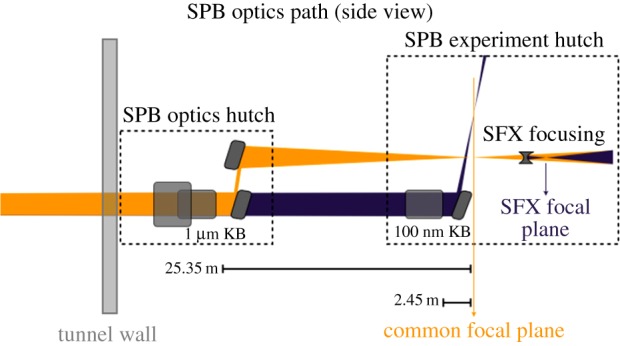
Schematic optical layout of the SPB instrument optics and experiment hutches, in side view (from reference [9]). (Online version in colour.)
The European XFEL sample environment group, with strong collaborations with the Centre for Free-Electron Laser Science (CFEL) laboratory in Hamburg and with the University of Uppsala, is developing sample injection devices, another very important component of the instrumentation. Similarly, the optical lasers group is in charge of providing suitable burst mode lasers with a time structure adapted to that of the X-ray bunches.
As mentioned earlier, the soft X-ray baseline instruments foreseen on SASE3, the SCS and SQS instruments, also have potential for biological imaging of larger, non-reproducible objects.
The SFX consortium is coordinated by the CFEL Laboratory of Hamburg and includes participating institutes from Germany, Slovakia, Sweden, Switzerland, the UK and the USA, plus the European Molecular Biology Laboratory (EMBL). The consortium proposes to deliver instrumentation that will allow one to perform nano-crystallography with the so-called spent beam at the SPB instrument. This will involve the installation of refocusing optics downstream of the SPB sample chamber, an additional sample chamber, and an additional 4 Mpx AGIPD for measuring crystallographic diffraction patterns.
Owing to the highly integrated nature of the instrumentation involved, a very close cooperation of the SPB staff with the SFX team is anticipated, including having the SFX scientists and engineers physically located at European XFEL for a large fraction of their time, both in the construction and in the operation phase.
The two further user consortia devoted to structural biology are dataXpress and XFEL-based integrated biology infrastructure (XBI). The DataXpress consortium aims to contribute to the evaluation of the huge amount of data that coherent imaging and nano-crystallographic experiments are expected to produce at the European XFEL. Through determining sensible veto signals and using data reduction techniques to minimize the amount of data that must be stored, the dataXpress proposal plans to make efficient handling of the approximately 15 TB per day that may be collected at the European XFEL possible. Led by the CFEL institute in Hamburg, it comprises institutions from Germany, Sweden and the USA. The consortium for the XBI plans to contribute an approximately 550 m2 biology laboratory to be housed in the European XFEL main building on the laboratory level—one floor above the instruments. This will allow for sample preparation techniques including crystal growth, cell culturing and more. This laboratory space and support are proposed to be available to users awarded beamtime who wish to prepare samples on site. XBI is coordinated by the Hamburg outstation of EMBL, and includes institutions from Denmark, Germany, Russia and Sweden.
It appears therefore that the deployment of four stations (SPB including SFX, SCS and SQS) with state-of-the-art capabilities for structural imaging, plus the ancillary facilities for sample preparation and data evaluation constitute an integrated experimental system of high potential for a flourishing structural biology activity at the European XFEL.
4. Optimization of operation for structural biology experiments
The very large number of pulses per unit time at the European XFEL is an obvious advantage for experiments, if the instrumentation is able to respond to this high rate, owing to the shorter acquisition time to collect a sufficiently complete dataset, then this can make the difference between feasible and non-feasible experiments, in some cases, e.g. those dealing with short-lived samples. In addition to the large number of pulses, the European XFEL aims to offer users a very large flexibility in operation modes, allowing an optimization of the number of pulses per pulse train that are directed to a given instrument and of the spacing between successive pulses inside those trains, so as to optimize the experiment with respect to detector performance, sample consumption (often an important parameter for biological samples), timescale of investigated phenomena, and possibly other considerations.
The presently envisaged mode of operation of the facility, when all components are fully commissioned, consists of two shifts of 12 h per day of operation. In each 12 h shift, three experimental stations, one on each of the three undulators, are in use, sharing a fraction of the 27 000 pulses s−1 that are produced. The basic pulse-sharing devices are three types of kickers, magnets capable of imparting to the electron bunches a deviation from their trajectory.
The first type of kicker (‘slow’ kicker) is used to direct the electron bunches, normally drifting towards the SASE1 undulator, to the SASE2 undulator, i.e. towards the upper branch of figure 2. This kicker can be activated between bunch trains (in the 99.4 ms gaps; figure 1) or halfway through a bunch train, so as to split the train between the two electron beamlines where SASE1 and SASE2 are located. In the latter case, the bunches within a few tens of µs of the splitting point are not usable for lasing, so that a fraction of the 2700 bunches are ‘lost’.
The second ‘fast’ kicker can, on the other hand, be activated or deactivated bunch-by-bunch; it can however, owing to a lower precision, only remove bunches from the lasing trajectory and direct them to the beam dump, not to a lasing undulator. This is, however, useful for producing a bunch pattern ‘à la carte’, as one may, for example, wish one bunch out of three, i.e. with a minimum spacing exceeding 600 ns, or an irregular or logarithmic spacing pattern. Therefore, without altering the standard filling pattern at the injection and therefore keeping a stationary loading on the machine, one of the three experimental groups sharing the beam can control the pulse pattern by suppressing unwanted bunches without perturbing the stable operation of the beam for other users. This possibility is especially attractive for structural biology users concerned by optimization of precious sample consumption: it can be used to match the repetition rate of the pulses to the rate of the sample delivery device, or to investigate dynamical processes with characteristic timescales exceeding the minimum pulse spacing of 220 ns without wasting detector memory space.
Finally, the third type of kicker imparts a more gentle kick to the bunches at the entrance of SASE1 that is sufficient to trigger an oscillation of the orbit through the undulator that prevents SASE lasing. The beam that reaches SASE3 is then ‘fresh’, i.e. not affected by the microbunching and by the increased energy spread caused by intense lasing emission. This guarantees effective SASE3 lasing whatever the upstream settings of SASE1. It allows the coexistence of users of SASE1 and SASE3 instruments and sharing of bunches with optimal lasing conditions for both.
A word of caution is however in order: the use of such sophisticated tools for exquisite control of bunch distribution and optimized delivery requires extensive commissioning of the whole facility, and cannot be expected on ‘day one’. It is however definitely in the plans to exploit the capabilities of the European XFEL as a leading user facility for structural biology.
In addition to the flexibility in the bunch distribution, there is some flexibility also in the individual pulse properties, such as intensity and spectral width. The self-seeding method [10], recently tested with success [11] at the LCLS, allows a narrowing of the SASE bandwidth (typically a few parts per thousands) to the 10−4 range, and a better reproducibility of the wavelength from shot to shot. Other techniques, such as tapering, taking advantage of the tunability of the gap of individual undulator segments, promise a one order of magnitude intensity increase [12]. This could facilitate achieving the conditions required for single-particle imaging.
In conclusion, the European XFEL offers new, unprecedented opportunities for structural biology due to its uniquely high repetition-rate source, its ability to share the beam between three undulators, the careful and dedicated design of the X-ray instrumentation, as well as the provision of support such as dedicated biology laboratories on-site and optimized data analysis techniques.
References
- 1.Redeke L, et al. 2013. Natively inhibited Trypanosoma brucei cathepsin B structure determined by using an X-ray laser. Science 339, 227–230. ( 10.1126/science.1229663) [DOI] [PMC free article] [PubMed] [Google Scholar]
- 2.Emma P, et al. 2010. First lasing and operation of an Ångstrom-wavelength free-electron laser. Nat. Photon. 4, 641–647. ( 10.1038/nphoton.2010.176) [DOI] [Google Scholar]
- 3.Ishikawa T, et al. 2012. A compact X-ray free-electron laser emitting in the sub-Ångström region. Nat. Photon. 6, 540–544. ( 10.1038/nphoton.2012.141) [DOI] [Google Scholar]
- 4.Ganter R. (ed) 2010. SwissFEL Conceptual Design Report, PSI Report 10-06; see also Oberta P, Flechsig U. and Abela R. 2011 The SwissFEL facility and its preliminary optics beamline layout, in Proc. SPIE 8078, Advances in X-ray Free-Electron Lasers: Radiation Schemes, X-ray Optics, and Instrumentation, 807805 (20 May 2011).
- 5.Han J-H, Kang H-S, Ko IS. 2012. Status of the PAL-XFEL project. In Proc. IPAC2012, New Orleans, LA, USA, pp. 1735–1737. See http://accelconf.web.cern.ch/Accelconf/IPAC2012/index.htm. [Google Scholar]
- 6.Altarelli M, et al. (ed.) 2006. XFEL: the European X-ray free-electron laser - technical design report See http://xfel.desy.de/technical_information/tdr/tdr/.
- 7.Saldin EL, Schneidmiller EV, Yurkov MV. 1999. The physics of free-electron lasers. Berlin, Germany: Springer. [Google Scholar]
- 8.Enrich B, et al. 2011. The adaptive gain integrating pixel detector AGIPD a detector for the European XFEL. Nucl. Instrum. Methods A 633, S11–S14. ( 10.1016/j.nima.2010.06.107) [DOI] [Google Scholar]
- 9.Mancuso AP, Aquila A, Borchers G, Giewekemeyer K, Reimers N. 2013. Technical design report: scientific instrument single particles, clusters and biomolecules (SPB). Available on the web page of the European XFEL See http://www.xfel.eu/documents/technical_documents/.
- 10.Geloni G, Kocharyan V, Saldin E. 2011. A novel self-seeding scheme for hard x-ray FELs. J. Mod. Opt. 58, 1391–1403. ( 10.1080/09500340) [DOI] [Google Scholar]
- 11.Amann J, et al. 2012. Demonstration of self-seeding in a hard-X-ray free-electron laser. Nat. Photon. 6, 693–698. ( 10.1038/nphoton.2012.180) [DOI] [Google Scholar]
- 12.Serkez S, Kocharyan V, Saldin E, Geloni G. 2013. Nonlinear undulator tapering in conventional SASE regime at baseline electron beam parameters as a way to optimize the radiation characteristics of the European XFEL. (http://arxiv.org/abs/1309.3149) [Google Scholar]