

Abstract
X-ray free-electron lasers overcome the problem of radiation damage in protein crystallography and allow structure determination from micro- and nanocrystals at room temperature. To ensure that consecutive X-ray pulses do not probe previously exposed crystals, the sample needs to be replaced with the X-ray repetition rate, which ranges from 120 Hz at warm linac-based free-electron lasers to 1 MHz at superconducting linacs. Liquid injectors are therefore an essential part of a serial femtosecond crystallography experiment at an X-ray free-electron laser. Here, we compare different techniques of injecting microcrystals in solution into the pulsed X-ray beam in vacuum. Sample waste due to mismatch of the liquid flow rate to the X-ray repetition rate can be addressed through various techniques.
Keywords: liquid jets, serial femtosecond, crystallography, X-ray free-electron laser
1. Introduction
The emerging technique of serial femtosecond crystallography (SFX) has the potential to be a transformative innovation in structural biology. The technique makes use of the idea that biomolecules can be imaged with high-intensity X-ray pulses without visible effects of radiation damage, if the pulses are shorter than the relevant timescales of the damage processes [1]. In SFX, this ‘diffract-before-destruction’ approach uses protein micro- and nanocrystals instead of the larger crystals used in conventional macromolecular crystallography (MX). Several experiments have already shown the potential of this new method for room temperature high-resolution structure determination [2–5]. As every nanocrystal that is hit by an unattenuated X-ray pulse is destroyed after the pulse has passed through, a new nanocrystal must be supplied for the next pulse. Therefore, the nanocrystals must be replaced with the X-ray repetition rate, which is currently 120 Hz at the Linac Coherent Light Source (LCLS) and up to 1 MHz at future superconducting linacs. In addition, the protein nanocrystals used for SFX have to be introduced into the X-ray beam in a solvated state at room temperature, and ideally there should only be one crystal in the beam per X-ray pulse. Thereby, millions of diffraction patterns from protein nanocrystals in random orientation and varying sizes are collected in a serial fashion.
The requirements for SFX sample delivery are therefore:
(1) Room temperature, in solution (mother liquor).
(2) Minimal background scattering from the solution.
(3) Constant replenishment of nanocrystals at a rate of the X-ray free-electron laser (XFEL) pulses (currently 120 Hz at the LCLS).
(4) Every X-ray pulse should hit a crystal.
(5) Delivery into vacuum for minimal background scattering.
(6) Low sample consumption, no sample waste, every crystal in the liquid should be hit by an X-ray pulse.
(7) No damage inflicted on the sample due to the injection process (no undue shear forces, charging, etc.)
(8) Reliable operation without intervention for many hours.
2. Continuous liquid injection into vacuum
Most of these requirements can be fulfilled with a liquid jet injection scheme, where the jet has a diameter similar to the X-ray beam. The easiest way to generate a liquid jet is by pressurizing a liquid through an orifice. The emerging liquid forms a free jet, which breaks up into droplets to minimize its free surface energy. The droplets have about twice the diameter of the jet and have an average spacing of 4.5d, where d is the orifice diameter (figure 1). This so-called Rayleigh–Plateau break-up [6] can be triggered by an external acoustic excitation which results in a monodispersed, unidirectional, periodic stream of droplets phase-locked to the excitation signal (figure 1). The injection of a water jet into vacuum was first demonstrated in 1988 [7].
Figure 1.
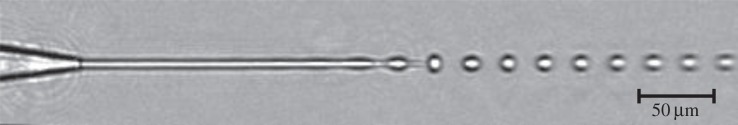
Rayleigh jet issued from a 8 μm diameter nozzle. Rayleigh–Plateau instability causes breakup of the jet into droplets. The droplet break-up is triggered by a piezo transducer mounted to the nozzle, which is oscillating at 3.3 MHz.
For SFX measurements, it is preferred to hit the unbroken jet with the X-ray beam before the breakup into droplets occurs, thereby maximizing the sample hit rate. Rayleigh jets have two distinct disadvantages, one of which renders them undesirable for SFX: (i) very high flow rate of 0.4–7 ml min−1 for jet diameters of 10–40 μm due to the high jet speed of about 100 m s−1. (ii) Susceptibility to clogging for the jet diameters required for SFX. The jet diameter should be comparable to the X-ray beam diameter in order to avoid sample waste and high background scattering. As the XFEL beam diameter is currently between 10 and 0.2 μm (at the LCLS), this would require an orifice diameter of the same dimension, which is impractical and would clog immediately [8,9]. In addition, a Rayleigh jet nozzle is prone to freezing in vacuum if the jet is interrupted for any amount of time.
This problem was solved by a new approach, the so-called gas dynamic virtual nozzle (GDVN) [10]. Based on the observation that the shear and pressure forces of a coflowing gas stream can focus a liquid jet to a diameter smaller than the orifice diameter [11], a miniature nozzle was developed which generates a micro-metre-sized jet without the associated clogging problems of the Rayleigh jet [10]. These nozzles contain a capillary for the liquid sample suspension of typically 50 μm inner diameter, which is tapered at the end. A surrounding coaxial gas stream accelerates the liquid through a gas aperture of similar size and so reduces the diameter of the liquid column by a factor of about 10. The volumetric flow rate of these nozzles is typically about 10 μl min−1 (flow speed approx. 10 m s−1) and the jet diameter is about 4 μm, although 0.3 μm (with flow speed of approx. 100 m s−1) has been achieved with much effort [12]. These GDVN nozzles (figure 2) are the most common sample delivery device for structural biology experiments at XFELs [2–4,13–16]. Although the GDVN nozzles have been a spectacular success for structural biology XFEL measurements, these experiments have shown one major disadvantage of these devices: the flow rate of the GDVN is not matched to the X-ray pulse repetition rate of the currently existing XFELs (120 Hz@LCLS and 60 Hz@SACLA). For typical SFX measurements at the LCLS with a protein crystal concentration of 109 ml−1 (protein concentration 1 mg ml−1, crystal size less than 2 μm) [3], a jet diameter of 5 μm and a flow speed of 10 m s−1, about 1.6 nl of sample suspension or about 1600 crystals are wasted between two X-ray pulses, i.e. are not probed by the X-ray beam. For this reason, the amount of sample suspension needed for a complete SFX dataset is about 10 ml, or 10 mg of protein [3]. Future XFEL light sources based on superconducting linacs will have a pulse repetition rate of about 1 MHz, which is matched to the flow rate of the GDVN nozzle and so solves this sample waste problem. The shock wave emanating from each destroyed crystal might limit the rate at which pulses can arrive as it may destroy adjacent crystals.
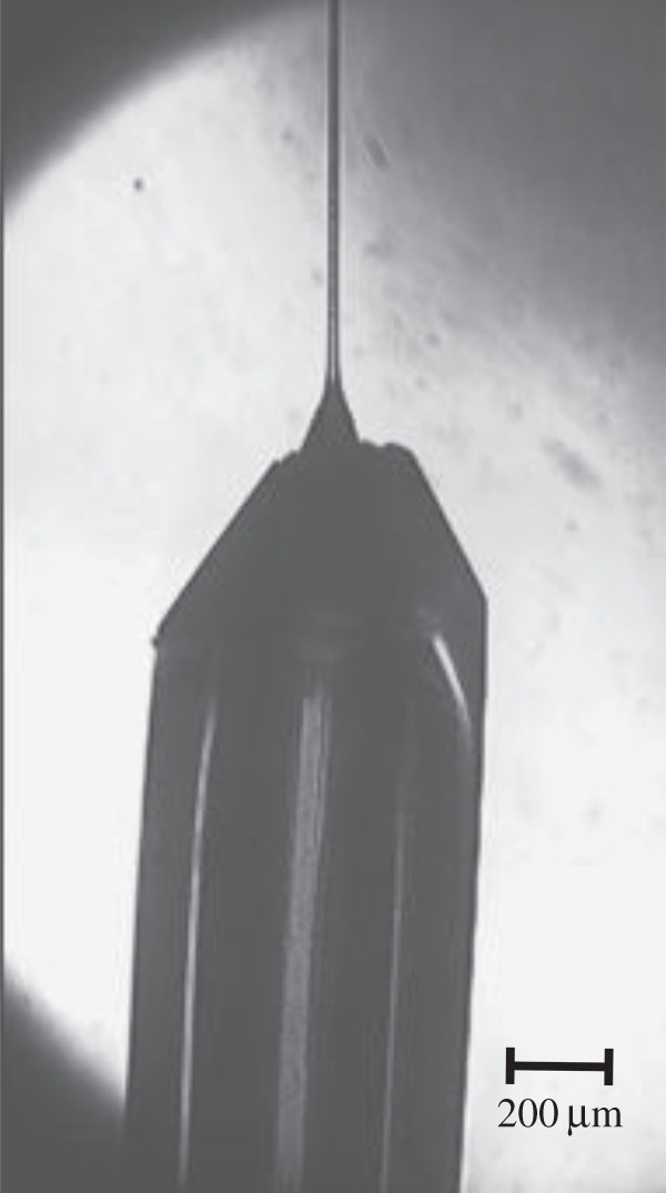
Figure 2.

GDVN nozzles as used at the LCLS, the arrow indicates the flow direction. (a) Nozzle is mounted in a stainless steel nozzle holder, which allows adjustment of the position of the inner capillary relative to the gas-focusing aperture. These nozzles can be disassembled and repaired if clogging occurs. (b) Glued nozzle, the inner capillary is glued into the outer tube. No repair or adjustment is possible. The length of the nozzle is about 5 cm.
To deal with the currently available low repetition rate of warm linac-based XFELs, efforts are underway to reduce the sample consumption in SFX. Initial experiments with Rayleigh jets have shown that a reduction of their very high flow rates by a factor of about 10 is possible with the previously described electrospray-assisted Rayleigh jet in vacuum [9], but operation is far from user-friendly and the ejected liquid is highly charged, which may be undesirable for some protein crystals.
The GDVN nozzle has already a reduced flow rate, which is about two orders of magnitude smaller compared with a standard Rayleigh jet. The first injector with a lower flow rate than a GDVN that has been used for SFX at an XFEL is also based on electrostatic charging of the liquid in vacuum, but here the charged liquid is emitted as a continuous filament, which eventually dehydrates and becomes a solid thread. The process is appropriately termed ‘electrospinning’ [17]. This technique differs from regular electrospray in that the length of the unbroken microjet is extended, and droplet formation is delayed or prevented by adding glycerol and/or polyethylene glycol. Flow rates of 0.17–3.1 µl min−1 have been reported with this device [17] and it has been used in three SFX measurements at the LCLS so far [17–19]. Freezing of the jet due to evaporative cooling in vacuum requires the addition of an antifreeze such as glycerol to the protein crystal suspension. The method therefore requires protein crystals that are stable in the presence of antifreeze and electrostatic charging.
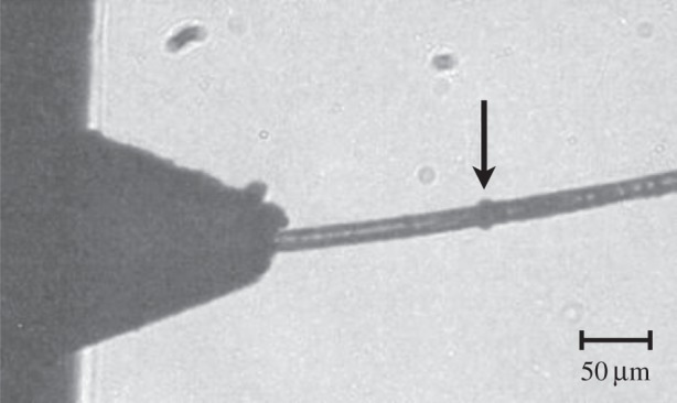
A similar injection mechanism, which has not been used so far at an XFEL, has been observed in the author's laboratory: a solution of photosystem I microcrystals in a 1.4 M sucrose solution could be ejected out of a modified GDVN into vacuum with no additional liquid back pressure (only ambient pressure relative to vacuum) at low flow rates of 100–300 nl min−1. The diameter of the stream can be thinned down to about 20 µm (figure 3) by coaxially flowing helium gas, and settling of microcrystals is not a problem, because the sucrose concentration can be adjusted to a value which allows for neutral buoyancy of the crystals in the solution. The stream does not break up into droplets, but becomes solid due to dehydration in vacuum. It is not yet clear, however, how far downstream from the nozzle the solidification occurs.
Figure 3.
Sucrose solution containing photosystem I crystals is injected into vacuum at a low flow rate of 300 nl min−1. The liquid capillary of 50 μm inner diameter protrudes out of the gas aperture. Ambient pressure acts on the liquid, and helium gas at 170 psi supply pressure is used as the coflowing gas. The liquid jet diameter can be reduced from the initial inner diameter of the liquid capillary to about 20 μm by the coflowing gas.
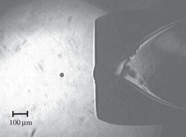
A further reduction in flow rate is possible by using a liquid with extremely high viscosity, such as lipidic cubic phase (LCP). LCP has about the same viscosity as Dow Corning high vacuum grease (viscosity ca 500 Pa-s at 25°C). This value is much higher than for aqueous solutions, from which microscale jets have previously been formed. The bicontinuous lipidic mesophase LCP [20] has shown great potential as a crystallization medium for human membrane proteins, and possibly also soluble proteins [21]. LCP can be extruded through a 10–50 µm diameter capillary at high pressures of several thousand psi and produces a continuous linear stream in vacuum and at ambient pressure, if a coaxially flowing gas is used to prevent curling of the stream. First experiments with this material at the LCLS showed much promise for structure determination of membrane protein crystals grown in LCP. In figure 4, the extrusion process into vacuum at the LCLS is shown, while the LCP stream is being hit by the X-ray laser pulses. The X-ray impacts are visible as black dots on the stream. The flow rate was 300 pl min−1, so low that the LCLS repetition rate had to be reduced from the usual highest rate of 120 to 1 Hz to avoid hitting the same sample area twice. By increasing the liquid pressure, the flow rate can be adjusted to match the X-ray repetition rate. Motivated by these first successful experiments, a new high viscosity injector has been designed, which uses pressure amplification to extrude LCP, and it has been used at the LCLS to solve two G-protein-coupled receptor structures [22,23]. Full SFX datasets can be obtained with only 0.3 mg of protein per dataset. With the new injector, the LCP flow speed can be set high enough (2–3 mm s−1), that the maximum X-ray pulse repetition rate of 120 Hz can be used, while each X-ray pulse irradiates fresh and undamaged sample. To achieve this flow speed, a pressure of about 3500 psi has to be applied to the LCP. As LCP is a non-Newtonian fluid, it flows in close to plug flow conditions, i.e. the velocity profile across the capillary is flat, and there is expected to be only very little shear stress acting on the embedded crystals. The extrusion mechanism may also be useful for other high viscosity liquids containing protein microcrystals and similar low sample consumption may be achieved. In this way, the consumption of protein for a complete dataset may be reduced from millilitres of solution to microlitres, both at a few milligram per millilitre molecular concentration. This small quantity is stored in the nozzle body itself, and so does not require the elaborate system of tube delivery, antisettler device [24] and HPLC pumps supplying protein crystals from outside the XFEL hutch. The LCP system thus provides high hit rate, low protein consumption and the prospect of an integrated nanocrystal growth medium.
Figure 4.
LCP injection into vacuum: a frame from a movie taken with the in vacuum camera during measurements at the LCLS. The nozzle shadow is on the right, and the X-ray pulse impact on the LCP jet (arrow) can be seen as a black bubble. LCP is extruded at a flow rate of 300 pl min−1. The pressure on the LCP was 3000 psi. The LCP extrusion speed was so slow that the X-ray pulse repetition rate at the LCLS had to be reduced to 1 Hz. X-ray energy: 9.4 keV, X-ray beam attenuated to 7%. LCP stream diameter: 20 μm.
3. Pulsed liquid injection into vacuum
Reducing the sample flow rate when using low viscosity liquids is possible with pulsed sample delivery. One technological realization of this is the ubiquitous inkjet technology; however, the droplets are typically far too large for use at XFELs. The most promising realization for vacuum injection is the ‘squeeze-type’ drop-on-demand (DOD) injector, where a volume reduction with an associated high-pressure wave is produced periodically inside a capillary containing the sample [25]. This pressure wave is generated with a piezo transducer and results in the ejection of a droplet through an orifice at the exit of the capillary. The ejected droplet has about the same diameter as the orifice (figure 5). Achieving small droplets (sub 10 µm) with such a DOD system is difficult for the same reason as for the Rayleigh jet nozzle: any contamination similar in size to the orifice diameter will clog the nozzle [26,27]. The smallest droplet size achieved in the author's laboratory from a protein crystal suspension using a piezoelectric DOD nozzle is about 30 μm (14 pl droplet volume). The sample flow rate at a droplet ejection rate of 120 Hz (the highest current X-ray repetition rate of the LCLS) is then about 100 nl min−1, comparable to the low LCP flow rate. Crystal settling is not a problem with DOD nozzles if sucrose is added to the crystal suspension at a concentration that allows for neutral buoyancy of the crystals. Synchronization of 30 μm or smaller droplets with the LCLS beam will probably be difficult, as it has been observed in the author's laboratory that the droplet speed varies so that droplets do not remain synchronized if they contain crystals similar in size to the droplets. In addition, DOD systems are not readily compatible with a vacuum environment, because evaporative cooling tends to freeze the liquid between ejection events and thereby clog the orifice. It may be possible to use larger on-demand droplets containing microcrystals at XFELs in air or in a helium environment. A larger droplet size however increases sample consumption. For example, for 70 µm droplets at 120 Hz, the flow rate is 1.2 μl min−1, approaching the lower limit for the GDVN nozzles. In addition, background scattering from the liquid will be increased.
Figure 5.
DOD nozzle producing 30 μm diameter droplets, image taken with synchronized 100 ns flash exposures from an LED, repetition rate of droplet ejection was 120 droplets s−1 into ambient air.
Reducing the flow rate of the GDVN nozzle could be achieved by operating in a pulsed mode, whereby the liquid flow is turned on and off in a periodic fashion at 120 Hz with a fast high-pressure solenoid valve. In preliminary tests, the liquid flow of a GDVN nozzle was turned on and off with a HPLC valve (Rheodyne) and the switching time was measured with a high-speed camera (Photron FastCam SA4). The turn-on time with this valve is 300 μs (figure 6), whereas the turn-off time is about 2 ms. At 120 Hz X-ray repetition rate, this would allow a reduction in sample consumption by a factor of about 4, or even lower, if the turn-on/-off time can be reduced with a faster valve. Another possibility to pulse the GDVN is by operating the nozzle in dripping mode, i.e. reducing the liquid pressure to the point where a continuous jet is no longer emitted, but liquid filaments (figure 7) are expelled periodically. If no continuous jet is emitted, the liquid accumulates at the end of the inner capillary until it is ejected by the shear and pressure forces of the coflowing gas, after the drop has accumulated enough volume [28]. Dripping rates of 120 Hz can be achieved by adjusting the flow rate, but at the moment it is unclear whether this dripping process can be synchronized with the LCLS X-ray pulses.
Figure 6.
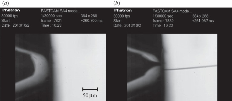
Switch on time measurement of a pulsed GDVN nozzle. Two images from a high-speed camera movie recorded at 30 000 frames s−1. The liquid is turned on with a fast valve and the time difference between (a) and (b) is 367 µs. The gas flow is uninterrupted, only the liquid is pulsed. The time is shown on the upper right in milliseconds. The apparent offset of the stream from the centre in (b) is due to refraction in the outer glass tube.
Figure 7.
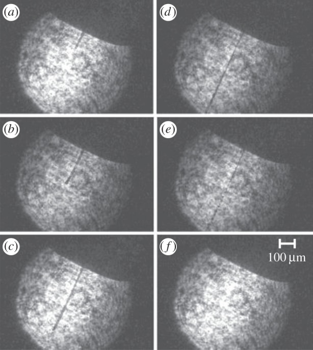
GDVN nozzle operating in dripping mode, periodically ejecting liquid filaments with trailing droplets. (a–f) A sequence of images from a movie, taken during the ejection of one liquid filament, imaged with stroboscopic laser diode illumination. The liquid filament is initially compact (a–c), and then breaks up into droplet at the trailing end (d,e).
4. Conclusion
Liquid jet injectors have been highly successful for structure determination of proteins at XFELs. In combination with the Monte–Carlo method of integration of partial reflections [29] from protein nanocrystals in random orientations, it has been shown that SFX using a GDVN liquid jet injector is capable of providing near atomic-resolution density maps of soluble proteins [2,4]. The pulse repetition rate of existing warm linac FELs is too low to make use of all the microcrystals in the sample solution with the existing GDVN nozzles. Further improvements and innovations in injector design will enable optimal use of all microcrystals in the sample solution without so much waste. Sample waste due to a mismatch between X-ray pulse repetition rate and liquid jet speed can be addressed by using higher viscosity liquids or pulsed liquid sources. A novel injector is under development, which allows the use of highly viscous liquids.
Funding statement
This work was supported by the National Science Foundation (award nos. MCB 1021557 and MCB 1120997) and its BioXFEL Science and Technology Center (NSF 1231306).
References
- 1.Neutze R, Wouts R, van der Spoel D, Weckert E, Hajdu J. 2000. Potential for biomolecular imaging with femtosecond X-ray pulses. Nature 406, 752–757. ( 10.1038/35021099) [DOI] [PubMed] [Google Scholar]
- 2.Boutet S, et al. 2012. High-resolution protein structure determination by serial femtosecond crystallography. Science 337, 362–364. ( 10.1126/science.1217737) [DOI] [PMC free article] [PubMed] [Google Scholar]
- 3.Chapman HN, et al. 2011. Femtosecond X-ray protein nanocrystallography. Nature 470, 73–77. ( 10.1038/nature09750) [DOI] [PMC free article] [PubMed] [Google Scholar]
- 4.Redecke L, et al. 2013. Natively inhibited Trypanosoma brucei Cathepsin B structure determined by using an X-ray laser. Science 339, 227–230. ( 10.1126/science.1229663) [DOI] [PMC free article] [PubMed] [Google Scholar]
- 5.Aquila A, et al. 2012. Time-resolved protein nanocrystallography using an X-ray free-electron laser. Opt. Express 20, 2706 ( 10.1364/OE.20.002706) [DOI] [PMC free article] [PubMed] [Google Scholar]
- 6.Rayleigh L. 1879. On the capillary phenomena of jets. Proc. R. Soc. Lond. 29, 71–97. ( 10.1098/rspl.1879.0015) [DOI] [Google Scholar]
- 7.Faubel M, Schlemmer S, Toennies JP. 1988. A molecular beam study of the evaporation of water from a liquid jet. Z. Phys. D Atoms Mol. Clusters 10, 269–277. ( 10.1007/BF01384861) [DOI] [Google Scholar]
- 8.Kunnus K, et al. 2012. A setup for resonant inelastic soft X-ray scattering on liquids at free electron laser light sources. Rev. Sci. Instrum. 83, 123109 ( 10.1063/1.4772685) [DOI] [PubMed] [Google Scholar]
- 9.Weierstall U, Doak RB, Spence JCH, Starodub D, Shapiro D, Hembree GG, Fromme P, Chapman HN. 2007. Droplet streams for serial crystallography of proteins. Exp. Fluids 44, 675–689. ( 10.1007/s00348-007-0426-8) [DOI] [Google Scholar]
- 10.DePonte DP, Weierstall U, Schmidt K, Warner J, Starodub D, Spence J, Doak RB. 2008. Gas dynamic virtual nozzle for generation of microscopic droplet streams. J. Phys. D Appl. Phys. 41, 195505 ( 10.1088/0022-3727/41/19/195505) [DOI] [Google Scholar]
- 11.Gañán-Calvo AM. 1998. Generation of steady liquid microthreads and micron-sized monodisperse sprays in gas streams. Phys. Rev. Lett. 80, 285 ( 10.1103/PhysRevLett.80.285) [DOI] [Google Scholar]
- 12.Deponte D, Mckeown J, Weierstall U, Doak R. 2011. Towards ETEM serial crystallography: electron diffraction from liquid jets. Ultramicroscopy 111, 824–827. ( 10.1016/j.ultramic.2010.11.036) [DOI] [PubMed] [Google Scholar]
- 13.Barends TRM, et al. 2013. De novo protein crystal structure determination from X-ray free-electron laser data. Nature 505, 244–247. ( 10.1038/nature12773) [DOI] [PubMed] [Google Scholar]
- 14.Weierstall U, Spence JCH, Doak RB. 2012. Injector for scattering measurements on fully solvated biospecies. Rev. Sci. Instrum. 83, 035108 ( 10.1063/1.3693040) [DOI] [PubMed] [Google Scholar]
- 15.Johansson LC, et al. 2012. Lipidic phase membrane protein serial femtosecond crystallography. Nat. Methods 9, 263–265. ( 10.1038/nmeth.1867) [DOI] [PMC free article] [PubMed] [Google Scholar]
- 16.Barends TRM, et al. 2013. Anomalous signal from S atoms in protein crystallographic data from an X-ray free-electron laser. Acta Crystallogr. D 69, 838–842. ( 10.1107/S0907444913002448) [DOI] [PubMed] [Google Scholar]
- 17.Sierra RG, et al. 2012. Nanoflow electrospinning serial femtosecond crystallography. Acta Crystallogr. D 68, 1584–1587. ( 10.1107/S0907444912038152) [DOI] [PMC free article] [PubMed] [Google Scholar]
- 18.Kern J, et al. 2013. Simultaneous femtosecond X-ray spectroscopy and diffraction of photosystem II at room temperature. Science 340, 491–495. ( 10.1126/science.1234273) [DOI] [PMC free article] [PubMed] [Google Scholar]
- 19.Kern J, et al. 2012. Room temperature femtosecond X-ray diffraction of photosystem II microcrystals. Proc. Natl Acad. Sci. USA 109, 9721–9726. ( 10.1073/pnas.1204598109) [DOI] [PMC free article] [PubMed] [Google Scholar]
- 20.Caffrey M, Cherezov V. 2009. Crystallizing membrane proteins using lipidic mesophases. Nat. Protoc. 4, 706–731. ( 10.1038/nprot.2009.31) [DOI] [PMC free article] [PubMed] [Google Scholar]
- 21.Aherne M, Lyons JA, Caffrey M. 2012. A fast, simple and robust protocol for growing crystals in the lipidic cubic phase. J. Appl. Crystallogr. 45, 1330–1333. ( 10.1107/S0021889812037880) [DOI] [PMC free article] [PubMed] [Google Scholar]
- 22.Weierstall U, et al. 2014. Lipidic cubic phase injector facilitates membrane protein serial femtosecond crystallography. Nat. Commun. 5, 3309 ( 10.1038/ncomms4309) [DOI] [PMC free article] [PubMed] [Google Scholar]
- 23.Liu W, et al. 2013. Serial femtosecond crystallography of G protein-coupled receptors. Science 342, 1521–1524. ( 10.1126/science.1244142) [DOI] [PMC free article] [PubMed] [Google Scholar]
- 24.Lomb L, Steinbrener J, Bari S, Beisel D, Berndt D, Kieser C, Lukat M, Neef N, Shoeman RL. 2012. An anti-settling sample delivery instrument for serial femtosecond crystallography. J. Appl. Crystallogr. 45, 674–678. ( 10.1107/S0021889812024557) [DOI] [Google Scholar]
- 25.Zoltan SI. 1972. Pulsed droplet ejecting system. US Patent No. 3,683,212, Washington, DC, USA.
- 26.Chen A, Basaran O. 2002. A new method for significantly reducing drop radius without reducing nozzle radius in drop-on-demand drop production. Phys. Fluids 14, L1–L4. ( 10.1063/1.1427441) [DOI] [Google Scholar]
- 27.Chen A, Basaran O. 2003. Method and apparatus for producing drops using a drop-on-demand dispenser. US Patent No. 6,513,894, Washington, DC, USA.
- 28.Herrada M, Gañán-Calvo A, Ojeda-Monge A, Bluth B, Riesco-Chueca P. 2008. Liquid flow focused by a gas: jetting, dripping, and recirculation. Phys. Rev. E 78, 036323 ( 10.1103/PhysRevE.78.036323) [DOI] [PubMed] [Google Scholar]
- 29.Kirian RA, et al. 2010. Femtosecond protein nanocrystallography-data analysis methods. Opt. Express 18, 5713–5723. ( 10.1364/OE.18.005713) [DOI] [PMC free article] [PubMed] [Google Scholar]