Abstract
Two-photon microscopy has been used in conjunction with micro-optics, such as GRIN lenses, to access subcortical structures in the intact mouse brain. In this study, we demonstrate the use of thick glass windows, or plugs, for high-resolution, large field-of-view two-photon imaging of the hippocampus in a live mouse. These plugs are less expensive, yield larger fields-of-view and are simpler to use than GRIN lenses while requiring less tissue removal compared to previous methods based on cortical ablation. To demonstrate the capabilities of our system, we show fluorescence images of dendritic spines in the CA1 region of the hippocampus in THY1-YFP transgenic mice.
OCIS codes: (180.0180) Microscopy, (180.2520) Fluorescence microscopy, (180.4315) Nonlinear microscopy
1. Introduction
Two-photon microscopy (TPM) has been the prevailing technique for deep-tissue fluorescence microscopy since its introduction in 1990 [1]. Using near-infrared excitation light, which is less prone to light-scattering, standard TPM protocols can reach penetration depths on the order of a few hundred microns in untreated tissue [2]. More recent developments have sought to push the deep-tissue imaging capabilities of TPM even further. For example, longer wavelength (>1300 nm) excitation light has been used for two- and three-photon excitation [3–5] to achieve imaging depths up to 1.6 mm in mouse brain, while regenerative amplifiers [6, 7] have been used to image up to 1 mm in cortex. These techniques utilize the well-established cranial window technology, which provides access to a large imaging field-of-view on the order of ~1mm [8] in the intact mouse brain. Nevertheless, long wavelength excitation is limited to red dyes, and cannot access the most effective calcium-sensitive indicators, while regenerative amplifiers are generally not tunable and substantially increase the cost and complexity of the system.
Alternatively, TPM can be combined with micro-optics. For example, micro-prisms [9–11] and gradient index (GRIN) lenses [12–14] allow imaging up to several millimeters deep into mouse brain in living animals. GRIN lenses can be specifically designed to access sub-cortical structures. In practice, however, GRIN lenses are subject to severe optical aberrations that scale with lens length. As a result, the resolving power of this technology is generally inferior to that of conventional TPM. For example, the lateral point spread function of an uncorrected 0.6 numerical aperture (NA) GRIN lens has a full width half maximum that is almost twice the diffraction-limited value [13]. To alleviate aberrations, Murray et al. demonstrated that a piece of cover glass placed between the GRIN lens and objective can greatly improve spherical aberrations [15]. The cover glass served the purpose of introducing positive spherical aberrations that compensated for the negative spherical aberrations caused by the GRIN lens. Any over-compensation was corrected by adjusting the correction collar on the microscope objective.
In order to both correct aberrations and achieve a higher numerical aperture, Barretto et al. demonstrated the use of a coupled plano-convex lens and matching GRIN lens [16]. The combination was chosen such that the plano-convex lens compensated for spherical aberrations introduced by the GRIN lens. This system achieved near-diffraction-limited performance in the center of the field-of-view. However, the outer diameter of the lens system was 1.4 mm, and chronic imaging of sub-cortical structures would require insertion of a cannula that would further increase the amount of cortex that must be removed. Moreover, the compound lens system is expensive and limits the field-of-view to ~500 μm, while off-axis aberrations effectively limit the field-of-view to just a few tens of microns [17]. Adaptive optics have been used to expand the usable field of view to ~200 μm, but with significantly increased system cost and complexity [18].
An alternative approach, first demonstrated by Katz and associates [19], is to ablate the overlying cortex and insert a plastic or metal cannula filled with agar. This enabled the use of conventional, well-corrected, high-numerical-aperture microscope objectives. However, the outer diameter of the cannula was ~2.3 mm, requiring the removal of a significant amount of cortex.
Here, we demonstrate a modification of the approach by Katz that combines the advantages of cranial windows with those afforded by implantable GRIN lenses [20]. Our technique uses a simple micro-optic element that is combined with TPM for large field-of-view subcortical imaging in the intact mouse brain. We show that by imaging through a cylindrical glass window, or plug, 1.5 mm in diameter and extending the full thickness of cortex, we can achieve a large field-of-view ~1,000 μm in diameter. The higher refractive index of the glass plug increases the available numerical aperture for a given plug diameter, thus minimizing the amount of tissue that must be removed (see Fig. 1(a) and 1(b)). Moreover, by adjusting the correction collar on our objective lens to correct for the spherical aberrations introduced by the glass plug, we are able to maintain the resolving power required to identify dendritic spines on the CA1 hippocampal neurons of THY1-YFP transgenic mice. Finally, we demonstrate that our system allows for chronic imaging of the same animal over months. As a result, it provides a high–resolution, relatively inexpensive and easily implemented method for sub-cortical imaging.
Fig. 1.
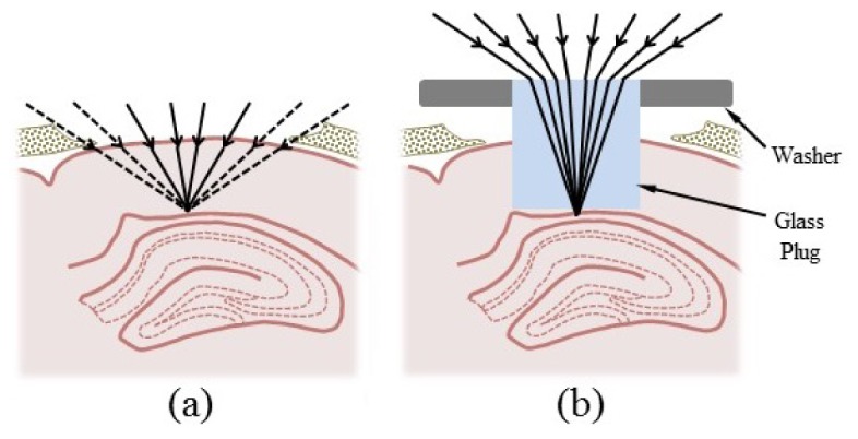
Glass plug optics and placement in the brain. (a) Removal of a 1.5-mm-diameter cortical region above hippocampus would normally result in significant clipping of rays from high-numerical aperture objectives. (b) The higher refractive index of the plug prevents the clipping of rays by cortical tissue and maximizes the available numerical aperture.
2. Materials and methods
2.1 Microscope apparatus and imaging protocol
All images were collected using a custom-built multiphoton microscope based on a BX51 upright microscope (Olympus America, Center Valley, PA). The excitation source was a MaiTai Ti:sapphire mode-locked laser (Spectra-Physics, Mountain View, CA) tuned to a wavelength of 886 nm to excite yellow fluorescent protein (YFP). Laser power was modulated via a half-wave plate and linear polarizer (Thorlabs, Newton, NJ) and the excitation light was focused using one of three air objectives: a LUCPlanFLN 40X/0.6 NA objective with a correction collar for up to 2 mm of glass (Olympus, Japan), a Plan Fluor 20X/0.45 NA objective with a correction collar for up to 2 mm of glass (Nikon, Japan) or an XL Flour 4X/0.28 NA air objective (Olympus, Japan).
Collected fluorescence was reflected into a homebuilt filter and detector housing using a 785 DCXR dichroic mirror (Chroma, Bellows Falls, VT). The housing was fit with an HC125-02 photomultiplier tube (PMT; Hamamatsu Corporation, Bridgewater, NJ) and a 525/50 nm emission filter (Chroma, Rockingham, VT) to isolate the fluorescent signal. ScanImage software (Pologruto et al. 2003) was used for image acquisition, with the resolution set to 1024x1024 or 2048x2048 pixels and the scan speed set to 2 or 4 ms per line.
All mice were imaged at least 3 weeks after surgery for plug insertion. The animals exhibited no obvious abnormal behaviors. They were anesthetized with an intraperitoneal injection of ketamine (100 mg/kg) and xylazine (10 mg/kg) and were restrained onto a modified gimbal mount (#SL8ABM; Newport Corporation, Irvine, CA) assembly using the surgically installed head post. This set-up minimized motion artifact, especially at high magnification settings, and the gimbal mount enabled easy alignment of the plug to prevent any aberrations due to tilt relative to the optical axis. The plug was aligned by using the gimbal mount to bring the entire circumference of the plug surface into focus in the same plane. The gimbal mount assembly was then fixed onto a motorized stage (ASI Imaging, Eugene, OR) to allow positioning of the plug beneath the objective lens and focusing of the excitation laser light onto the hippocampus.
2.2 Glass plugs
All cylindrical glass plugs were manufactured from BK7 glass (n = 1.5) and had both a diameter and thickness of 1.5 mm (BMV Optical Technologies, Canada). Plugs were attached to aluminum washers (#1421409; Bossard, Elk Grove Village, IL) using quick-dry cyanoacrylate glue such that the plug was positioned in the center opening of the washer and both the surface of the washer and the surface of the plug were flush with one another. The washer enabled easy attachment of the plug to the skull during surgery and had the added advantage of being large enough to cover and seal off the craniotomy once the plug was inserted.
2.3 Point spread function characterization
The point spread function (PSF) of our system was characterized using the second harmonic generation (SHG) signal from 100 nm barium titanate (BaTiO3) nanoparticles (Sigma-Aldrich, St. Louis, MO). These nanoparticles were dispersed in 1% agarose gel and imaged through a BK7 glass disc 1 cm in diameter and 1.5 mm in thickness (BMV Optical Technologies, Canada) that had been suspended on top of the gel. As noted by Murray et al. [15], the SHG signal from BaTiO3 nanoparticles is robust to photobleaching and saturation, therefore making these particles better suited to PSF characterization experiments than fluorescent beads. Moreover, we note that the glass disc provides an accurate representation of the glass plug with respect to induced aberrations since both elements were manufactured from the same glass substrate and were both of identical thickness. The larger diameter of the disc merely provided a greater area within which BaTiO3 nanoparticles could be isolated and imaged. To generate the SHG signal, 800 nm laser light was focused into the agarose sample using the 40X 0.6 NA objective equipped with a correction collar. The signal was then isolated using a 400/10 nm emission filter (Omega Optical Inc., Brattleboro, VT) and collected using an HC125-02 PMT positioned below the sample. Measurements were acquired for the 40X 0.6 NA objective alone, with the correction collar set to zero, and also for the objective coupled to the glass disc, with the correction collar set to 1.5 mm of glass. The data was analyzed using a custom MATLAB program to determine the 1/e half-widths of the bead images.
2.4 Field-of-view quantification
The effective field-of-view of our system was quantified by imaging the surface of a flat fluorescent sample (e.g. a fluorescent slide or 1% agarose gel combined with fluorescent dye), through a glass plug. For the 4X 0.28 NA objective, the available field-of-view of the objective was sufficiently large to capture the entire bottom surface of the plug in a single frame. For the 40X 0.6 NA objective, however, it was necessary to scan the small field-of-view of the objective across the region of interest and then stitch together the resulting frames to generate a similar image. A line profile extending from the center of the plug to its edge was then recorded from the fluorescence images and plotted vs. distance from the plug center. This plot depicted the fall-off in the fluorescent signal and the distance at which the fluorescence decreased to half its maximum value represented the radius of the effective field-of-view. The diameter was then twice this value.
2.5 Animal surgeries
A THY1-YFP transgenic mouse was weighed and the appropriate dose of buprenorphine (0.1 mg/kg) was administered as analgesia. The mouse was then anesthetized with ketamine (100 mg/kg) and xylazine (10 mg/kg) via an intraperitoneal injection. When it was no longer responsive to a firm toe pinch, the mouse was restrained onto a stereotactic device (#51625; Stoelting, Wood Dale, IL). Using surgical scissors and a scalpel blade, hair and skin were removed to expose an area of skull slightly larger than the circular opening on the custom cut titanium head post. The area was cleaned, using sterilized saline, and dried. The head post was attached to the skull using self-adhesive dental cement, such that its circular opening was centered 2 mm below bregma and 1.5 mm to the right of midline. Once the cement was dry (~30 min), a 3 mm x 3 mm craniotomy, also centered 2 mm below bregma and 1.5 mm to the right of midline, was made using a dental drill (see Fig. 2(a) ). After the square flap of skull was lifted away, a 27-gauge needle, with its tip slightly bent to form a claw, was used to pierce the dura and pull it to one side, exposing the brain. If any bleeding occurred during this step, the area was continuously irrigated with sterilized physiological saline until bleeding stopped. Once the area was clear of blood, a blunted 25-gauge needle was used to aspirate a column of cortex approximately 1.5 mm in diameter. This was accomplished in steps, as follows (see Fig. 2(a)). First, the needle was lowered in the center of the craniotomy, 100-200 μm deep, and immediately retracted. The needle was then translated ~500 μm anteriorly and then lowered once again to aspirate a second cavity anterior to the first. This was repeated three more times to aspirate similar cavities to the right, to the left and posterior to the center cavity. The region was then irrigated with saline until the bleeding stopped. If bleeding did not stop, the blood was allowed to coagulate for ~2 min before proceeding. This series of steps was repeated until white matter came into view, thus resulting in a cavity ~1.5 mm in diameter and ~0.7 mm below the surface of cortex. Once the region was cleared of all blood, the cavity was then filled with saline. The blunted needle on the vacuum was replaced with a 1-20 μl pipette tip to hold the plug and attached washer using suction (see Fig. 2(b)). The pipette tip was lowered to insert the plug into the cavity, thus pushing out any remaining saline. The whole region was then dried using a Kimwipe, taking care not to displace the inserted plug. The vacuum was turned off but the position of the pipette tip was maintained to hold the plug in place. Quick-dry cyanoacrylate glue was then used to attach the washer to the skull (see Fig. 2(c)). Once the glue was dry (~5 min), the pipette tip was retracted and any regions of skull still exposed were sealed with an additional application of glue. Once all glue had dried, Kwik-Cast sealant was applied to the circular opening of the head post and a metal cover slip was positioned to protect the entire area. Once the sealant was dry, the mouse was released from the stereotactic device and allowed to recover in a cage placed above a water-heated pad. Ibuprofen was administered via the mouse’s water bottle (5 ml for 250 ml of water) for three days post-surgery. All procedures described are approved by the Yale Institutional Animal Care and Use Committee.
Fig. 2.
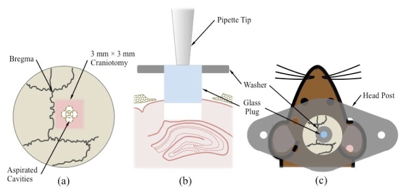
Key steps in glass plug implantation surgery. (a) Five aspirated cavities converge to form a larger ~1.5 mm diameter cavity centered within a 3 mm × 3 mm craniotomy. The craniotomy, in turn, is centered 2 mm below bregma and 1.5 mm to the right of midline. (b) A 1-20 µl pipette tip connected to a vacuum source is used to hold the glass plug and insert it into the excavated column of cortical tissue immediately above the hippocampus. (c) The plug is attached to a washer to facilitate attachment to the skull. A titanium head post is glued directly to the skull and can be attached to the gimbal mount assembly to immobilize the mouse during imaging.
2.6 Histology
In order to examine the degree of tissue damage induced by the plug insertion surgery, hemotoxylin-eosin (H&E) stained histological slices of brain tissue surrounding the implantation site were prepared. Once all necessary in vivo imaging experiments were complete, a mouse that had had a glass plug in place for a significant amount of time (> 3 weeks) was anesthetized as described in the procedure above. Once a suitable plane of anesthesia had been reached, the mouse was then perfused with phosphate buffered saline and subsequently with 4% paraformaldehyde to induce fixation. The brain was then extracted from the cranium, the glass plug was removed, and the whole brain was embedded in paraffin for slicing and staining.
3. Results and discussion
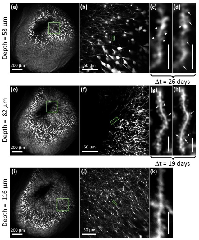
Representative images of YFP-labeled CA1 hippocampal pyramidal neurons acquired using chronically inserted glass plugs are presented in Fig. 3 . Correction collars on the microscope objective were used to correct for the aberrations incurred by imaging through 1.5 mm of glass, except for the images acquired at low magnification using the 4X 0.28 NA objective that does not have a correction collar.
Fig. 3.
Two-photon images of yellow fluorescent protein expressing neurons in the CA1 region of the hippocampus acquired in vivo using the glass plug. Images in (a)-(c), (e)-(g) and (i)-(k) were acquired between 4.5 and 5 months post-surgery. Depths were measured optically from the bottom surface of white matter. Arrowheads in (c) and (g) identify spines that have withdrawn and arrows in (d) and (h) identify spines that have developed over a time period (Δt) of 26-days ((c) to (d)) and 19-days ((g) to (h)). Δt describes the amount of time that elapsed between the acquisition dates of the two images. Scale bars for (c), (d), (g), (h) and (k) are 5 μm.
As shown in Fig. 3(a), 3(e) and 3(i), our system achieves a large field-of-view within which dendritic spines remain easily resolvable at all image depths sampled, regardless of whether they arise towards the center or towards the periphery of the field-of view. This indicates that the entire imaging volume accessed by our system is of use for high-resolution subcortical imaging despite the inevitable vignetting of marginal rays at the periphery of the field. Indeed, PSF measurements indicate that adjustment of the correction collar on the 40X 0.6 NA objective is sufficient to correct for the aberrations induced by the plug so as to maintain diffraction-limited resolution (Fig. 4(a) ). However, tilting of the plug with respect to the optical access can induce significant aberrations (Fig. 4(b)), as demonstrated by ray fans calculated using Zemax ray-tracing software (Radiant Zemax, LLC, Redmond, WA). These aberrations reduce the resolution, but also lead to lower Strehl ratios. The efficiency of two-photon excitation scales as the square of the Strehl ratio, such that tilts of just a few degrees for moderate-NA lenses will result in significant reductions in fluorescence (Fig. 4(c)).
Fig. 4.
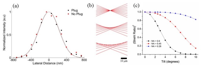
Resolution of glass plug system. (a) PSF characterization using 100 nm barium titanate crystals for the 40X 0.6 NA objective alone (red) and coupled to the plug with the correction collar optimized (black) indicates near diffraction-limited resolution in both cases. 1/e half widths are 105% and 110% of the diffraction-limited value, respectively. (b) Ray fans with NA = 0.6 for plug tilts of 0°, 2.5°, and 5° demonstrate loss of resolution for small tilts. (c) The square of the Strehl ratio versus plug tilt for NA = 0.6 (black), 0.45 (red), and 0.28 (blue). Lower NA systems are much less sensitive to tilt.
Compared to other approaches, our protocol allows for efficient tissue excavation. We aspirated a 1,500 μm diameter column of tissue and access approximately two thirds of this diameter in effective field-of-view. This is demonstrated in Fig. 5(a) for the 4X 0.28 NA objective, where we access a field-of-view 1080 µm in diameter and in Fig. 5(b) for the 40X 0.6 NA objective, where we access a field-of-view 980 µm in diameter. For comparison, Barretto et al. excavated a column of cortical tissue ~1,400 μm in diameter [16] but achieve a field of view that is only a few tens of microns in diameter due to increased off-axis aberrations [17, 18].
Fig. 5.
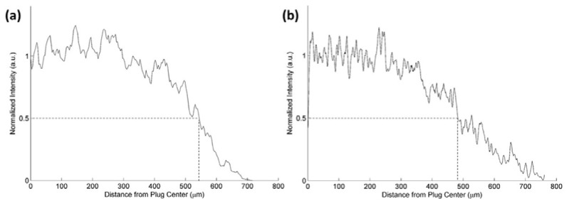
Quantification of the effective field-of-view accessed through the glass plug via (a) the 4X 0.28 NA objective, and (b) the 40X 0.6 NA objective. The distance from the center of the plug to the boundary at which fluorescence falls to half its maximum value is approximately 540 µm for the 4X objective and 490 µm for the 40X objective. These correspond to fields-of-view that are 70% and 60% of the plug diameter, respectively.
In Fig. 3(c), 3(d), 3(g) and 3(h), we illustrate the potential use of our system in the study of dendritic spine dynamics (reviewed in [21]). Repeated imaging of the same dendritic arbor shows spine withdrawal (Fig. 3(c) and 3(g), arrowheads) as well as the development of new spines (Fig. 3(d) and 3(h), arrows) over a period of 26 and 19 days. Previous studies have shown spine density and/or morphology in the CA1 region of the hippocampus to change with spatial learning [22] and certain pathological conditions such as Alzheimer’s disease [23, 24] and Huntington’s disease [25]. These studies, however, have been limited to slice preparations and cell cultures. Our proposed set-up may allow these correlations to be studied in vivo.
H&E staining of the region surrounding the plug implantation site indicates that the tissue remains largely intact and in its natural condition (Fig. 6 ). An indentation towards the left of the tissue surface accessed by the plug imaging face (Fig. 6(a)) may indicate slight over-aspiration in that region. Nevertheless, as shown in Fig. 6(b), the neurons of the hippocampus remain unaffected and the cell bodies maintain their smooth curvature in the CA1 region.
Fig. 6.
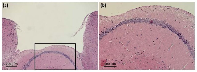
H&E histological images of the tissue surrounding the glass plug cavity. The slices imaged above were harvested 9 months after plug insertion surgery, from the same animal imaged in Fig. 3. (a) The tissue is maintained in its natural state and appears unaffected by the surgery and the long-term implantation of the plug. An indentation to the left of the imaged tissue surface suggests that the sub-region may have been slightly over-aspirated. (b) Neurons of the underlying hippocampus are largely intact and the smooth curvature of the cell body layer suggest that the region suffered no compression damage due to the placement of the glass plug.
The approach demonstrated here can be further improved by using high-refractive-index glasses for the plugs, which would enable larger numerical apertures. In addition, adaptive optics may be used in combination with larger numerical aperture objectives to compensate for the aberrations induced by the glass plugs, including aberrations stemming from tilting of the plug relative to the optic axis.
4. Conclusion
In summary, we have presented the use of glass plugs for long-term, chronic imaging of pyramidal neurons in the CA1 region of the hippocampus in THY1-YFP transgenic mice. The plugs allow for high-resolution imaging of dendritic spines over large fields-of-view while minimizing tissue removal. The protocol is easy to implement, requiring only relatively inexpensive microscope objectives typically used for cell culture, while the plugs themselves cost only ~$85 each. Moreover, we show that our protocol provides an alternative method for studying changes in dendritic spine structure and number.
Acknowledgments
We would like to thank Dr. Markus Wölfel, Dr. Richard Torres and Dr. Eben Olson for many helpful discussions. This work was supported by the National Science Foundation under CAREER Award DBI-0953902.
References and links
- 1.Denk W., Strickler J. H., Webb W. W., “Two-photon laser scanning fluorescence microscopy,” Science 248(4951), 73–76 (1990). 10.1126/science.2321027 [DOI] [PubMed] [Google Scholar]
- 2.Helmchen F., Denk W., “Deep tissue two-photon microscopy,” Nat. Methods 2(12), 932–940 (2005). 10.1038/nmeth818 [DOI] [PubMed] [Google Scholar]
- 3.Horton N. G., Wang K., Kobat D., Clark C. G., Wise F. W., Schaffer C. B., Xu C., “In vivo three-photon microscopy of subcortical structures within an intact mouse brain,” Nat. Photonics 7(3), 205–209 (2013). 10.1038/nphoton.2012.336 [DOI] [PMC free article] [PubMed] [Google Scholar]
- 4.Kobat D., Durst M. E., Nishimura N., Wong A. W., Schaffer C. B., Xu C., “Deep tissue multiphoton microscopy using longer wavelength excitation,” Opt. Express 17(16), 13354–13364 (2009). 10.1364/OE.17.013354 [DOI] [PubMed] [Google Scholar]
- 5.Kobat D., Horton N. G., Xu C., “In vivo two-photon microscopy to 1.6-mm depth in mouse cortex,” J. Biomed. Opt. 16(10), 106014 (2011). 10.1117/1.3646209 [DOI] [PubMed] [Google Scholar]
- 6.Mittmann W., Wallace D. J., Czubayko U., Herb J. T., Schaefer A. T., Looger L. L., Denk W., Kerr J. N. D., “Two-photon calcium imaging of evoked activity from L5 somatosensory neurons in vivo,” Nat. Neurosci. 14(8), 1089–1093 (2011). 10.1038/nn.2879 [DOI] [PubMed] [Google Scholar]
- 7.Theer P., Hasan M. T., Denk W., “Two-photon imaging to a depth of 1000 microm in living brains by use of a Ti:Al2O3 regenerative amplifier,” Opt. Lett. 28(12), 1022–1024 (2003). 10.1364/OL.28.001022 [DOI] [PubMed] [Google Scholar]
- 8.Holtmaat A., Bonhoeffer T., Chow D. K., Chuckowree J., De Paola V., Hofer S. B., Hübener M., Keck T., Knott G., Lee W.-C. A., Mostany R., Mrsic-Flogel T. D., Nedivi E., Portera-Cailliau C., Svoboda K., Trachtenberg J. T., Wilbrecht L., “Long-term, high-resolution imaging in the mouse neocortex through a chronic cranial window,” Nat. Protoc. 4(8), 1128–1144 (2009). 10.1038/nprot.2009.89 [DOI] [PMC free article] [PubMed] [Google Scholar]
- 9.Andermann M. L., Gilfoy N. B., Goldey G. J., Sachdev R. N., Wölfel M., McCormick D. A., Reid R. C., Levene M. J., “Chronic Cellular Imaging of Entire Cortical Columns in Awake Mice Using Microprisms,” Neuron 80(4), 900–913 (2013). 10.1016/j.neuron.2013.07.052 [DOI] [PMC free article] [PubMed] [Google Scholar]
- 10.Chia T. H., Levene M. J., “Microprisms for in vivo multilayer cortical imaging,” J. Neurophysiol. 102(2), 1310–1314 (2009). 10.1152/jn.91208.2008 [DOI] [PubMed] [Google Scholar]
- 11.T. H. Chia and M. J. Levene, “Multi-layer in vivo imaging of neocortex using a microprism,” Cold Spring Harbor Protocols 2010, pdb prot5476 (2010). [DOI] [PubMed]
- 12.Jung J. C., Schnitzer M. J., “Multiphoton endoscopy,” Opt. Lett. 28(11), 902–904 (2003). 10.1364/OL.28.000902 [DOI] [PubMed] [Google Scholar]
- 13.Levene M. J., Dombeck D. A., Kasischke K. A., Molloy R. P., Webb W. W., “In vivo multiphoton microscopy of deep brain tissue,” J. Neurophysiol. 91(4), 1908–1912 (2004). 10.1152/jn.01007.2003 [DOI] [PubMed] [Google Scholar]
- 14.Barretto R. P. J., Ko T. H., Jung J. C., Wang T. J., Capps G., Waters A. C., Ziv Y., Attardo A., Recht L., Schnitzer M. J., “Time-lapse imaging of disease progression in deep brain areas using fluorescence microendoscopy,” Nat. Med. 17(2), 223–228 (2011). 10.1038/nm.2292 [DOI] [PMC free article] [PubMed] [Google Scholar]
- 15.Murray T. A., Levene M. J., “Singlet gradient index lens for deep in vivo multiphoton microscopy,” J. Biomed. Opt. 17(2), 021106 (2012). 10.1117/1.JBO.17.2.021106 [DOI] [PubMed] [Google Scholar]
- 16.Barretto R. P., Messerschmidt B., Schnitzer M. J., “In vivo fluorescence imaging with high-resolution microlenses,” Nat. Methods 6(7), 511–512 (2009). 10.1038/nmeth.1339 [DOI] [PMC free article] [PubMed] [Google Scholar]
- 17.Gmbh GRINTECH, “High-NA Objective for 2-Photon Microscopy,” http://www.grintech.de/grin-lens-systems-for-medical-applications.html
- 18.Wang C., Ji N., “Characterization and improvement of three-dimensional imaging performance of GRIN-lens-based two-photon fluorescence endomicroscopes with adaptive optics,” Opt. Express 21(22), 27142–27154 (2013). 10.1364/OE.21.027142 [DOI] [PubMed] [Google Scholar]
- 19.Mizrahi A., Crowley J. C., Shtoyerman E., Katz L. C., “High-resolution in vivo imaging of hippocampal dendrites and spines,” The Journal of Neuroscience 24, 3147–3151 (2004). [DOI] [PMC free article] [PubMed] [Google Scholar]
- 20.Ziv Y., Burns L. D., Cocker E. D., Hamel E. O., Ghosh K. K., Kitch L. J., El Gamal A., Schnitzer M. J., “Long-term dynamics of CA1 hippocampal place codes,” Nat. Neurosci. 16(3), 264–266 (2013). 10.1038/nn.3329 [DOI] [PMC free article] [PubMed] [Google Scholar]
- 21.Rochefort N. L., Konnerth A., “Dendritic spines: from structure to in vivo function,” EMBO Rep. 13(8), 699–708 (2012). 10.1038/embor.2012.102 [DOI] [PMC free article] [PubMed] [Google Scholar]
- 22.Moser M. B., Trommald M., Andersen P., “An increase in dendritic spine density on hippocampal CA1 pyramidal cells following spatial learning in adult rats suggests the formation of new synapses,” Proc. Natl. Acad. Sci. U.S.A. 91(26), 12673–12675 (1994). 10.1073/pnas.91.26.12673 [DOI] [PMC free article] [PubMed] [Google Scholar]
- 23.Auffret A., Gautheron V., Repici M., Kraftsik R., Mount H. T., Mariani J., Rovira C., “Age-dependent impairment of spine morphology and synaptic plasticity in hippocampal CA1 neurons of a presenilin 1 transgenic mouse model of Alzheimer's disease,” The Journal of Neuroscience 29, 10144–10152 (2009). [DOI] [PMC free article] [PubMed] [Google Scholar]
- 24.del Valle J., Bayod S., Camins A., Beas-Zárate C., Velázquez-Zamora D. A., González-Burgos I., Pallàs M., “Dendritic spine abnormalities in hippocampal CA1 pyramidal neurons underlying memory deficits in the SAMP8 mouse model of Alzheimer’s disease,” J. Alzheimers Dis. 32(1), 233–240 (2012). [DOI] [PubMed] [Google Scholar]
- 25.Bulley S. J., Drew C. J. G., Morton A. J., “Direct visualisation of abnormal dendritic spine morphology in the hippocampus of the R6/2 transgenic mouse model of Huntington's Disease,” Journal of Huntington's Disease 1, 267–273 (2012). [DOI] [PubMed] [Google Scholar]


