Abstract
We present novel optical and mechanical designs for a microscope-integrated intraoperative optical coherence tomography (iOCT) system with enhanced function and ergonomics for visualization of ophthalmic surgical maneuvers. Integration of an electrically tunable lens allows rapid focal plane adjustment and iOCT imaging of both anterior and posterior segment tissue microstructures while maintaining parfocality with the ophthalmic surgical microscope. We demonstrate novel visualization of instrument positions relative to tissue layers of interest as colormap overlays onto en face OCT data, which may provide integrative display of volumetric information during surgical maneuvers. Finally, we implement a heads-up display system to provide real-time feedback as proof-of-principle for iOCT-guided ophthalmic surgery.
OCIS codes: (170.3880) Medical and biological imaging, (170.4460) Ophthalmic optics and devices, (170.4470) Ophthalmology, (170.4500) Optical coherence tomography, (170.4580) Optical diagnostics for medicine
1. Introduction
Optical coherence tomography (OCT) has become the gold standard for disease diagnostics and tracking therapeutic response in ophthalmology. Current-generation ophthalmic OCT systems provide high-resolution images of tissue layers in both the anterior and posterior segment that are poorly visualized with other conventional imaging modalities. Preoperative and perioperative OCT imaging, using tabletop [1] or microscope-coupled OCT systems [2], respectively, provide volumetric data sets of pathologic areas and are used for clinical decision-making and surgical planning. Intraoperative OCT would provide real-time visualization of tissue microstructure deformation, feedback on surgical maneuvers, and confirm completion of surgical goals.
The utility of intraoperative OCT has been demonstrated in clinical studies using perioperative imaging during ophthalmic surgical procedures. These studies include visualization of epiretinal membrane [3], macular hole [4], retinal detachment [5], vitreomacular traction [6, 7], and lamellar keratoplasty [8, 9]. These studies were predominantly performed using handheld or microscope-coupled (i.e., not parfocal to the surgical microscope) OCT systems. While perioperative imaging provides valuable information regarding structural changes as a result of surgical maneuvers, aiming the imaging field to identify regions-of-interest is difficult and without true surgical microscope integration, real-time surgical visualization and guidance is impossible.
Recently, several groups have developed intraoperative OCT systems that provide real-time feedback, including intraocular fiber probes [10, 11], integrated instruments [12, 13], and surgical microscope-coupled scan-heads [14–16]. Intraoperative ophthalmic OCT has not been limited to research devices and has been demonstrated using commercially available scan-heads and microscopes for perioperative imaging during surgery. These systems include the iVue (Optovue, Inc.) [17, 18], Visante OCT (Carl Zeiss Meditec, Inc.) [19, 20], and Envisu SDOIS (Bioptigen, Inc.) [5, 21]. Several studies have also demonstrated the utility of a fully integrated surgical microscope OCT for imaging ophthalmic surgical procedures using laboratory prototypes [22, 23] and commercial systems, including the Lumera 700 with integrated Rescan 700 (Carl Zeiss Meditec, Inc.) [24, 25] and HS Hi-R Neo 900 with OPMedT iOCT (Haag-Streit Surgical GmbH) [26]. While microscope-integrated OCT has ergonomic advantages over perioperative imaging, translation to the surgical suite has been limited because of a lack of commercial system availability and the bulky system design and cumbersome operation of research systems. Here, we present novel optical and mechanical designs for a microscope-integrated intraoperative OCT system (iOCT), which includes an electrically tunable lens and heads-up display (HUD) for real-time intraoperative feedback. We also demonstrate visualization methods to allow for integration of iOCT volumetric data into the surgical field and imaging of surgical maneuvers as a proof-of-principle for real-time image-guided surgery.
2. Methods
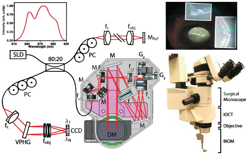
Microscope-integrated iOCT includes optical and mechanical design modifications to a previously described microscope-mounted OCT (MMOCT) [14, 15] (Fig. 1 ). The scan-head attaches at the base of a Leica ophthalmic surgical microscope (M844) and is mounted at the microscope nosepiece and secured by two preexisting attachment screws conventionally used to attach noncontact surgical viewing accessories (e.g., BIOM). The microscope objective is then mounted on a threaded adapter at the base of the iOCT, thus, extending the axial height of the microscope. To minimize interference with surgical ergonomics and maintain surgical field sterility, the axial height added by the iOCT was reduced from 120.5 mm (MMOCT) to 78.5 mm. To reduce the load on the pneumatic microscope swing arm, the body and base of the iOCT was rapid-prototyped using an ABS plastic substrate and reinforced with aluminum mounting and threaded brackets for a total of 4.32 lbs added weight (Media 1 (3.3MB, AVI) ). Optical mounts were designed into the iOCT body as a monolithic unit to ensure precision optical alignment and stability. Real-time intraoperative feedback and guidance was achieved using a 1024 x 768 pix. heads-up display (HUD) system optically coupled into the field-of-view (FOV) of one microscope ocular (Leica DI C800) using a 50:50 beamsplitter cube and interfaced with the OCT acquisition computer via VGA input. HUD opacity was adjusted by controlling the LCD display brightness. Real-time and post-processed OCT images may be displayed across the entire field at full brightness, completely obscuring the microscope view through one ocular; at low LCD brightness as an overlay, so both the HUD and microscope view were simultaneously visible; or projected at the periphery of the ocular field, simultaneously showing OCT and microscope views while avoiding potentially distracting or misleading overlaid features (Fig. 1).
Fig. 1.
Optical schematic and mechanical design of the microscope-integrated iOCT system (Media 1 (3.3MB, AVI) ). The system includes an electrically tunable lens to provide optimal focus for both anterior and posterior segment imaging while maintaining parfocality with the microscope oculars. OCT images were acquired with a modified commercial 36 kHz SDOCT engine. Inset photo shows surgical microscope ocular view with HUD overlaid live OCT cross-sections adjacent to conventional microscope view of retina. CCD, line-scan camera; DM, dichroic mirror; f, collimating, objective, scan, tube, and electrically tunable lenses; G, galvanometer scanners; M, reference and fold mirrors; PC, polarization controller; VPHG, grating.
The iOCT system was optically designed for both anterior and posterior segment imaging. The sample arm fiber output was collimated to a 1/e2 beam waist diameter of 2.64 mm (fc1 = 12.19 mm). The beam was then relayed across an electrically tunable lens and collimating lens (fc2 = 60 mm). The electrically tunable lens (EL-10-30-NIR-LD, Optotune AG), which provides 45-120 mm of focal length tuning, allowed real-time adjustment of the OCT focal plane to maintain parfocality with the microscope view. This allowed us to compensate for changes between the microscope and OCT focus when switching between anterior and posterior segment imaging, for different microscope zoom positions, and for refractive power differences between surgeons. To optimize lateral resolution and light efficiency, the iOCT includes a 19.8x expanding 4f-relay (fs = 7.3 mm, 2x f = 35 mm; ft = 144.8 mm, 2x f = 300 mm) to image a 52.4 mm scanning spot onto the back focal plane of the microscope objective (f = 186.7 mm). Anterior segment imaging was performed at the focal plane of the microscope objective with a measured FWHM lateral resolution of 5.1 μm (~25 μm Rayleigh range). The posterior segment was imaged using either a binocular indirect ophthalmomicroscope (BIOM, Oculus Surgical, Inc.) or direct/indirect surgical contact lenses (Volk Optical, Inc.), and the lateral resolution was limited by the optical properties of the eye. OCT images were acquired using a commercial SDOCT engine (Bioptigen, Inc.) with an NIR light source (870 nm center wavelength, 80 nm FWHM) and 2048 pix. line-scan CCD (Spyder3 2k, Teledyne Dalsa, Inc.). Using 700 μW of power at the sample, the system had a measured SNR of 109 dB at a line-rate of 36 kHz with an axial resolution of 5.2 μm in air and 6 dB falloff at 1.14 mm. The OCT engine was modified to pathlength-match the reference arm with the iOCT scan-head, and galvanometer drive signals were split and used to track iOCT scan field offsets for HUD co-registration.
Spatial compounding has previously been demonstrated as a method for acquiring video-rate tissue-instrument interactions using OCT [23, 27]. Briefly, repeated OCT volumetric data sets are acquired along the axis of a surgical instrument. The physical dimensions of the scan volume are asymmetric, with the short axis oriented perpendicular to and covering the entire width of the instrument and the long axis oriented along the instrument axis and covering both the instrument tip and tissue of interest. In post-processing, the volumetric data set is averaged along the short axis, yielding a single spatially compounded B-scan. Repeated volumes are used to record a motion capture, where each repeated volume is sparsely sampled to reduce motion artifacts during averaging. The spatial average ensures the entire tissue-instrument interaction is captured, improves the signal-to-noise (SNR) of each individual cross-sectional frame, and reduces shadowing effects from optically opaque instruments.
3. Results and discussion
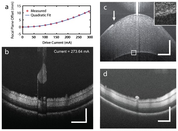
iOCT focal plane optimization using the tunable lens was quantified by measuring OCT signal reflectivity (Fig. 2(a) ). The lens was tuned over its entire tuning range (0-292.84 mA) at 25 mA increments, and an attenuated reflector was translated axially through the focal plane of the iOCT to find the position corresponding to the maximum power reflectivity. The OCT focal plane offset relative to 0 mA driving current yielded a quadratic fit, (), where is the offset in mm and iis the drive current in mA. The optimal iOCT focal position was established by adjusting the tunable lens to maximize OCT signal by either using custom software control on the OCT acquisition computer or foot pedal control. Reference arm position was manually adjusted and automatic dispersion compensation was performed in software to achieve optimal resolution during anterior and posterior segment imaging [28]. All B-scans were acquired with 2048 x 1000 pix. (axial x lateral). Figure 2(b) shows cross-sectional B-scans of a surgical instrument above retina while the tunable lens is driven across its tuning range. As expected, adjusting the focal plane changes both the lateral resolution and scattering signal. However, small variations in both axial and lateral position are also observed, which are attributed to tunable lens thickness changes and small alignment errors of the OCT beam incident on the tunable lens resulting in small angle shifts as the lens surface contour is changed, respectively (Media 2 (4.9MB, AVI) ). Anterior (Fig. 2(c)) and posterior (Fig. 2(d)) segment iOCT images were acquired in enucleated porcine eyes to demonstrate focal plane optimization. Here, the iOCT focal position was identified by first focusing the surgical microscope ocular view and then adjusting the tunable lens for parfocality. The anterior segment iOCT cross-section shows a corneal epithelial defect as a result of enucleation, and the magnified inset clearly shows the corneal endothelium (Fig. 2(c)). iOCT images of the porcine retina were imaged through a disposable surgical contact lens (Volk Optical, Inc.) and shows vessel cross-sections on the retinal surface and retinal layers (Fig. 2(d)).
Fig. 2.
Electrically tunable lens performance. (a) iOCT focus plane position measured over its tuning range. (b) Repeated B-scans of membrane scraper above retina in an enucleated porcine eye while electrically adjusting the focal plane (Media 2 (4.9MB, AVI) ). (c) iOCT B-scan of cornea and (d) retina in an enucleated porcine eye demonstrating anterior and posterior segment imaging with focal planes optimized using the tunable lens. Anterior segment B-scans showed a corneal epithelial defect (arrow) and clear visualization of the corneal endothelium (inset). The posterior segment was imaged using a direct surgical contact lens but may also be imaged using either a BIOM or indirect contact lenses. Scale bar: 500 µm.
Volumetric images of enucleated porcine retina were acquired with 2048 x 500 x 500 pix. (axial x lateral x lateral) in 6.9 s (Fig. 3 ). An aiming reticle was projected through the iOCT HUD using custom software, corresponding to a square volumetric acquisition field, to help the surgeon visualize the position and dimensions of the iOCT imaging field. The iOCT FOV was centered relative to the surgical microscope FOV at the beginning of each imaging session and regions-of-interest were centered within the aiming reticle by moving the eye, which is conventionally done during standard surgical procedures. Cross-sectional images show features of a diamond-dusted membrane scraper above the retina with a hyper-scattering tip, semi-transparent shaft, and opaque metallic neck (Media 3 (2.4MB, AVI) ). HUD allowed real-time visualization of orthogonal cross-sections across the center of the acquisition FOV during aiming (Fig. 3(c), (d)). Fast-axis cross-sectional images (Fig. 3(c)) were previewed live and the en face projection (Fig. 3(b)) was serially compiled and displayed during data acquisition.
Fig. 3.
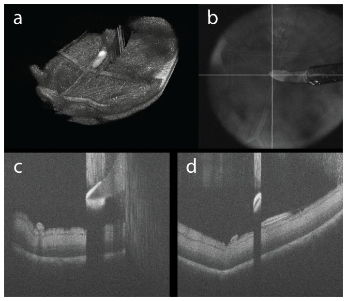
Membrane scraper above retina in an enucleated porcine eye. (a) Volumetric reconstruction, (b) en face projection and (c), (d) cross-sectional images comprised of 1024 x 500 x 500 pix. (Media 3 (2.4MB, AVI) ). Cross-sectional images of the surgical instrument shows a hyper-scattering diamond-dusted tip, semi-transparent silicone shaft, and opaque metallic neck.
Three-dimensional reconstruction and display was performed in post-processing (Fig. 3(a)). While cross-sectional images provide precise axial positions of surgical instruments relative to tissue microstructures of interest, the surgical field shows an en face view, which makes co-registration and integration of iOCT data complex. As a proof-of-principle, we implemented a simple two-layer segmentation that isolates the surface of the membrane scraper and inner limiting membrane (ILM) of the retina [29]. The difference of the axial positions of each segmented layer is then overlaid on to the en face projection of the iOCT volume as a colormap to show distance from retinal surface (Fig. 4 ). Co-registered colormaps between instruments and specific tissue layers of interest may be displayed as additional contrast on HUD systems to provide real-time guidance during surgical maneuvers. Current generation segmentation algorithms are too computationally intensive for real-time surgical guidance (1024 x 500 x 500 pix. data set was segmented in ~35 s). In practice, however, only cross-sectional images spanning the surgical instrument have to be segmented, and when combined with real-time visualization methods such as spatial compounding, only 5-10 B-scans will provide sufficient information, which can be segmented in <0.5 s.
Fig. 4.
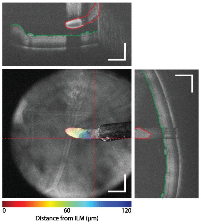
Surgical guidance using iOCT feedback. The surface of the membrane scraper (red) and ILM (green) were segmented on individual cross-sectional images (dotted line). An axial position difference is overlaid as a colormap on the en face view to provide integrative visualization of three-dimensional data of the membrane scraper position relative to the surface of the retina. Scale bar: 500 µm.
Demonstrations of real-time surgical maneuvers were visualized by acquiring spatially compounded volumetric data sets in enucleated porcine eyes. All spatially compounded motion captures were acquired with a volume size of 256 x 5 pix. (A-scans x B-scans) over a 5 x 0.5 mm FOV for an effective compounded frame-rate of 28.1 frames-per-second. The spatial compounding FOV was centered on the HUD reticle, with the fast scanning axis set either parallel or perpendicular to the axis of the surgical instrument for real-time visualization of cross-sectional images along the length or across the tip of the instrument, respectively. Figure 5(a) and Fig. 5(b) shows a motion capture parallel and perpendicular to the axis of the instrument, respectively, and shows real-time membrane scraping (Media 4 (1.8MB, AVI) and Media 5 (1.8MB, AVI) ). Figure 5(c) shows spatially compounded cross-sections along the axis of the membrane scraper as it compresses the retinal surface with differing amounts of pressure(Media 6 (2.1MB, AVI) ). All spatially compounded iOCT images are shown with corresponding recordings of the widefield surgical microscope view.
Fig. 5.
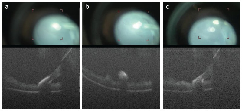
Visualization of intraoperative maneuvers using HUD guidance and spatial compounding. The iOCT imaging field was superimposed onto a microscope ocular to help localize the FOV for motion capture (red reticle in corresponding surgical recording). Spatial compounding frames were acquired during (a), (b) membrane scraping (Media 4 (1.8MB, AVI) , Media 5 (1.8MB, AVI) ) and (c) retinal compression (Media 6 (2.1MB, AVI) ). Cross-sectional OCT images were acquired (a), (c) along the axis of and (b) perpendicular to the membrane scraper. Spatial compounding volumes were acquired with 256 x 5 pix. (A-scans x B-scans) at 36 kHz line-rate for visualization of compounded intraoperative maneuvers at 28.1 frames-per-second.
Additional system improvements are required for further integration of OCT for intraoperative use. Integration of real-time layer segmentation and spatial compounding to provide axial positions of surgical instruments would allow for real-time integrative feedback on instrument depth. The current HUD aiming reticle is stationary and co-localized with the center of the surgical microscope FOV. Foot pedal control of the iOCT FOV would allow the surgeon more flexibility to image regions-of-interest, particularly features at the peripheral retina that are difficult to visualize by manipulating eye position. Finally, real-time automated instrument tracking would allow more flexible intraoperative imaging protocols that do not require manual co-registration of the surgical microscope and iOCT FOV.
4. Conclusions
We have demonstrated ophthalmic surgical microscope-integrated iOCT with electrically tunable focal plane adjustment and HUD for surgical guidance and feedback. iOCT was designed to provide improved functionality and ergonomics over previous implementations. Integration of a tunable lens provided us with the flexibility to rapidly focus iOCT for optimal imaging while maintaining parfocality with the surgical FOV. The design of a monolithic iOCT enclosure provides precision and sustained optical alignment while reducing overall weight and system complexity. As a proof-of-principle, enucleated porcine eyes were imaged using iOCT to demonstrated integration of OCT data with the surgical microscope view for real-time feedback. By using simple segmentation methods, we created colormaps overlaid onto en face projections of iOCT data as an integrative method of displaying the position of a surgical instrument relative to a tissue layer of interest as a contrast channel that may be easily interpreted and co-registered with the surgical field. Integration of a HUD and projection of an aiming reticle onto the surgical microscope field allows precise intraoperative positioning for volumetric imaging of regions-of-interest. Additionally, real-time visualization of the iOCT FOV was crucial for ensuring surgical maneuvers were within view when acquiring spatially compounded data sets of live tissue-instrument interactions. These studies show the potential for iOCT-guided maneuvers and clinical decision-making in ophthalmic surgery.
Acknowledgments
We thank D. S. Petkovsek for assistance with segmentation and C. Calabrise for assistance with surgical simulation and data acquisition. This research was supported by US National Institutes of Health grant R01-EY023039-01 (YKT, SKS, JPE), Ohio Department of Development TECH-13-059 (YKT, SKS, JPE), and US National Institutes of Health grant K23-EY022947-01A1 (JPE). YKT is supported in part by Cleveland Clinic new investigator funds.
References and links
- 1.Stopa M., Bower B. A., Davies E., Izatt J. A., Toth C. A., “Correlation of pathologic features in spectral domain optical coherence tomography with conventional retinal studies,” Retina 28(2), 298–308 (2008). 10.1097/IAE.0b013e3181567798 [DOI] [PubMed] [Google Scholar]
- 2.Ide T., Wang J., Tao A., Leng T., Kymionis G. D., O’Brien T. P., Yoo S. H., “Intraoperative use of three-dimensional spectral-domain optical coherence tomography,”Ophthalmic surgery, lasers imaging: J. International Society for Imaging Eye 41, 250–254 (2010). [DOI] [PubMed] [Google Scholar]
- 3.Ray R., Barañano D. E., Fortun J. A., Schwent B. J., Cribbs B. E., Bergstrom C. S., Hubbard G. B., 3rd, Srivastava S. K., “Intraoperative microscope-mounted spectral domain optical coherence tomography for evaluation of retinal anatomy during macular surgery,” Ophthalmology 118(11), 2212–2217 (2011). 10.1016/j.ophtha.2011.04.012 [DOI] [PubMed] [Google Scholar]
- 4.Ehlers J. P., Xu D., Kaiser P. K., Singh R. P., Srivastava S. K., “Intrasurgical Dynamics of Macular Hole Surgery: An Assessment of Surgery-Induced Ultrastructural Alterations with Intraoperative Optical Coherence Tomography,” Retina 34(2), 213–221 (2014). 10.1097/IAE.0b013e318297daf3 [DOI] [PubMed] [Google Scholar]
- 5.Ehlers J. P., Ohr M. P., Kaiser P. K., Srivastava S. K., “Novel microarchitectural dynamics in rhegmatogenous retinal detachments identified with intraoperative optical coherence tomography,” Retina 33(7), 1428–1434 (2013). 10.1097/IAE.0b013e31828396b7 [DOI] [PubMed] [Google Scholar]
- 6.Ehlers J. P., Tam T., Kaiser P. K., Martin D. F., Smith G. M., Srivastava S. K., “Utility of intraoperative optical coherence tomography during vitrectomy surgery for vitreomacular traction syndrome,” Retina. In Press [DOI] [PMC free article] [PubMed]
- 7.Dayani P. N., Maldonado R., Farsiu S., Toth C. A., “Intraoperative use of handheld spectral domain optical coherence tomography imaging in macular surgery,” Retina 29, 1457–1468 (2009). [DOI] [PMC free article] [PubMed] [Google Scholar]
- 8.Knecht P. B., Kaufmann C., Menke M. N., Watson S. L., Bosch M. M., “Use of Intraoperative Fourier-Domain Anterior Segment Optical Coherence Tomography During Descemet Stripping Endothelial Keratoplasty,” Am. J. Ophthalmol. 150(3), 360–365 (2010). 10.1016/j.ajo.2010.04.017 [DOI] [PubMed] [Google Scholar]
- 9.De Benito-Llopis L., Mehta J. S., Angunawela R. I., Ang M., Tan D. T. H., “Intraoperative Anterior Segment Optical Coherence Tomography: A Novel Assessment Tool during Deep Anterior Lamellar Keratoplasty,” Am. J. Ophthalmol. 157(2), 334–341 (2014). 10.1016/j.ajo.2013.10.001 [DOI] [PubMed] [Google Scholar]
- 10.Joos K. M., Shen J. H., “Miniature real-time intraoperative forward-imaging optical coherence tomography probe,” Biomed. Opt. Express 4(8), 1342–1350 (2013). 10.1364/BOE.4.001342 [DOI] [PMC free article] [PubMed] [Google Scholar]
- 11.Han S., Sarunic M. V., Wu J., Humayun M., Yang C., “Handheld forward-imaging needle endoscope for ophthalmic optical coherence tomography inspection,” J. Biomed. Opt. 13, 020505 (2008). [DOI] [PubMed] [Google Scholar]
- 12.Song C., Park D. Y., Gehlbach P. L., Park S. J., Kang J. U., “Fiber-optic OCT sensor guided “SMART” micro-forceps for microsurgery,” Biomed. Opt. Express 4(7), 1045–1050 (2013). 10.1364/BOE.4.001045 [DOI] [PMC free article] [PubMed] [Google Scholar]
- 13.M. Balicki, J. H. Han, I. Iordachita, P. Gehlbach, J. Handa, R. Taylor, and J. Kang, “Single fiber optical coherence tomography microsurgical instruments for computer and robot-assisted retinal surgery,” Medical image computing and computer-assisted intervention: MICCAI ... International Conference on Medical Image Computing and Computer-Assisted Intervention 12, 108–115 (2009). 10.1007/978-3-642-04268-3_14 [DOI] [PubMed] [Google Scholar]
- 14.Ehlers J. P., Tao Y. K., Farsiu S., Maldonado R., Izatt J. A., Toth C. A., “Integration of a spectral domain optical coherence tomography system into a surgical microscope for intraoperative imaging,” Invest. Ophthalmol. Vis. Sci. 52(6), 3153–3159 (2011). 10.1167/iovs.10-6720 [DOI] [PMC free article] [PubMed] [Google Scholar]
- 15.Tao Y. K., Ehlers J. P., Toth C. A., Izatt J. A., “Intraoperative spectral domain optical coherence tomography for vitreoretinal surgery,” Opt. Lett. 35(20), 3315–3317 (2010). 10.1364/OL.35.003315 [DOI] [PMC free article] [PubMed] [Google Scholar]
- 16.Geerling G., Müller M., Winter C., Hoerauf H., Oelckers S., Laqua H., Birngruber R., “Intraoperative 2-dimensional optical coherence tomography as a new tool for anterior segment surgery,” Arch. Ophthalmol. 123(2), 253–257 (2005). 10.1001/archopht.123.2.253 [DOI] [PubMed] [Google Scholar]
- 17.De Benito-Llopis L., Mehta J. S., Angunawela R. I., Ang M., Tan D. T., “Intraoperative anterior segment optical coherence tomography: a novel assessment tool during deep anterior lamellar keratoplasty,” Am. J. Ophthalmol. 157(2), 334–341 (2014). 10.1016/j.ajo.2013.10.001 [DOI] [PubMed] [Google Scholar]
- 18.Miyakoshi A., Ozaki H., Otsuka M., Hayashi A., “Efficacy of Intraoperative Anterior Segment Optical Coherence Tomography during Descemet’s Stripping Automated Endothelial Keratoplasty,” ISRN Ophthalmol. 2014, 562062 (2014). 10.1155/2014/562062 [DOI] [PMC free article] [PubMed] [Google Scholar]
- 19.Kucumen R. B., Gorgun E., Yenerel N. M., Utine C. A., “Intraoperative use of AS-OCT during intrastromal corneal ring segment implantation,” Ophthalmic surgery, lasers imaging: J. International Society for Imaging Eye 43, S109–116 (2012). [DOI] [PubMed] [Google Scholar]
- 20.Hirnschall N., Amir-Asgari S., Maedel S., Findl O., “Predicting the Postoperative Intraocular Lens Position Using Continuous Intraoperative Optical Coherence Tomography Measurements,” Invest. Ophthalmol. Vis. Sci. 54(8), 5196–5203 (2013). 10.1167/iovs.13-11991 [DOI] [PubMed] [Google Scholar]
- 21.Lee L. B., Srivastava S. K., “Intraoperative spectral-domain optical coherence tomography during complex retinal detachment repair,” Ophthalmic surgery, lasers imaging: J. International Society for Imaging Eye 42, e71–74 (2011). [DOI] [PubMed] [Google Scholar]
- 22.Hahn P., Migacz J., O’Donnell R., Day S., Lee A., Lin P., Vann R., Kuo A., Fekrat S., Mruthyunjaya P., Postel E. A., Izatt J. A., Toth C. A., “Preclinical evaluation and intraoperative human retinal imaging with a high-resolution microscope-integrated spectral domain optical coherence tomography device,” Retina 33(7), 1328–1337 (2013). 10.1097/IAE.0b013e3182831293 [DOI] [PMC free article] [PubMed] [Google Scholar]
- 23.Ehlers J. P., Tao Y. K., Farsiu S., Maldonado R., Izatt J. A., Toth C. A., “Visualization of real-time intraoperative maneuvers with a microscope-mounted spectral domain optical coherence tomography system,” Retina 33(1), 232–236 (2013). 10.1097/IAE.0b013e31826e86f5 [DOI] [PMC free article] [PubMed] [Google Scholar]
- 24.Binder S., Falkner-Radler C. I., Hauger C., Matz H., Glittenberg C., “Feasibility of intrasurgical spectral-domain optical coherence tomography,” Retina 31(7), 1332–1336 (2011). 10.1097/IAE.0b013e3182019c18 [DOI] [PubMed] [Google Scholar]
- 25.Steven P., Le Blanc C., Velten K., Lankenau E., Krug M., Oelckers S., Heindl L. M., Gehlsen U., Hüttmann G., Cursiefen C., “Optimizing descemet membrane endothelial keratoplasty using intraoperative optical coherence tomography,” JAMA Ophthalmol. 131(9), 1135–1142 (2013). 10.1001/jamaophthalmol.2013.4672 [DOI] [PubMed] [Google Scholar]
- 26.Steven P., Le Blanc C., Velten K., Lankenau E., Krug M., Oelckers S., Heindl L. M., Gehlsen U., Hüttmann G., Cursiefen C., “Optimizing Descemet Membrane Endothelial Keratoplasty Using Intraoperative Optical Coherence Tomography,” JAMA Ophthalmol. 131(9), 1135–1142 (2013). 10.1001/jamaophthalmol.2013.4672 [DOI] [PubMed] [Google Scholar]
- 27.Y. K. Tao, J. P. Ehlers, C. A. Toth, and J. A. Izatt, “Visualization of vitreoretinal surgical manipulations using intraoperative spectral domain optical coherence tomography,” in SPIE Photonics West, 2011), 78890F–78890F–78810. [Google Scholar]
- 28.Wojtkowski M., Srinivasan V. J., Ko T. H., Fujimoto J. G., Kowalczyk A., Duker J. S., “Ultrahigh-resolution, high-speed, Fourier domain optical coherence tomography and methods for dispersion compensation,” Opt. Express 12(11), 2404–2422 (2004). 10.1364/OPEX.12.002404 [DOI] [PubMed] [Google Scholar]
- 29.Chiu S. J., Li X. T., Nicholas P., Toth C. A., Izatt J. A., Farsiu S., “Automatic segmentation of seven retinal layers in SDOCT images congruent with expert manual segmentation,” Opt. Express 18(18), 19413–19428 (2010). 10.1364/OE.18.019413 [DOI] [PMC free article] [PubMed] [Google Scholar]


