

Abstract
To increase the ability of brain-machine interfaces (BMIs) to control advanced prostheses such as the modular prosthetic limb (MPL), we are developing a novel system: the Hybrid Augmented Reality Multimodal Operation Neural Integration Environment (HARMONIE). This system utilizes hybrid input, supervisory control, and intelligent robotics to allow users to identify an object (via eye tracking and computer vision) and initiate (via brain-control) a semi-autonomous reach-grasp-and-drop of the object by the MPL. Sequential iterations of HARMONIE were tested in two pilot subjects implanted with electrocorticographic (ECoG) and depth electrodes within motor areas. The subjects performed the complex task in 71.4% (20/28) and 67.7% (21/31) of trials after minimal training. Balanced accuracy for detecting movements was 91.1% and 92.9%, significantly greater than chance accuracies (p < 0.05). After BMI-based initiation, the MPL completed the entire task 100% (one object) and 70% (three objects) of the time. The MPL took approximately 12.2 seconds for task completion after system improvements implemented for the second subject. Our hybrid-BMI design prevented all but one baseline false positive from initiating the system. The novel approach demonstrated in this proof-of-principle study, using hybrid input, supervisory control, and intelligent robotics, addresses limitations of current BMIs.
Index Terms: Brain-computer interface (BCI), Brain-machine interface (BMI), Electrocorticography (ECoG), Hybrid BCI, Intelligent robotics, Intracranial EEG (iEEG)
I. Introduction
Current brain-machine interfaces (BMIs) lack widespread clinical use due to their inability to provide paralyzed patients with reliable control of prosthetic devices to perform everyday tasks. The more than 100,000 Americans with complete quadriplegia [1] suffer a loss of autonomy that affects their general quality of life and the general health care with lifetime costs near five million dollars [2]. Surveys of patients with motor disabilities reinforce the limited state of functional rehabilitation that BMIs and other assistive technologies currently provide [3]. These studies show that patients who use assistive technology are most dissatisfied with their manipulation ability and they rank restoration of their ability to perform activities of daily living as highly important for future devices.
The shortcomings of current BMIs are no longer due to a lack of robotic ability. The modular prosthetic limb (MPL) developed by the Johns Hopkins Applied Physics Laboratory (JHU/APL) is an upper limb neuroprosthetic with 17 controllable degree of freedom (DOF) capable of performing a full range of activities of daily living [4]. While these capabilities are far greater than those offered by traditional prosthetics, they have not yet been fully utilized in a BMI. This is due, in part, to the current training paradigm of mapping independent DOFs to neural activity generated during volitional or imagined movements. Groups using this training paradigm have demonstrated multi-dimensional control in humans implanted with invasive multi-electrode arrays, electrocorticography (ECoG), and depth electrodes [5] [12]. While recent work demonstrating 7-DOF neural control with microelectrode arrays (MEAs) [6] is impressive, this still represents a fraction of potential robotic capabilities and requires sustained selective attention and mental effort by the patient to exert the low-level control necessary for performing basic tasks.
Limitations of current BMI technology have led researchers to develop novel methods of controlling robotic actuators. Three strategies have been explored to fully utilize robotic ability: hybrid BMIs, supervisory control, and intelligent robotics [13]. Hybrid BMIs combine a traditional input signal from the brain with an additional signal, which can also be from the brain (e.g., combining electroencephalography (EEG)-based SSVEP and P300 potentials for BMI) or from physiological signals such as electromyography (EMG) or electrooculography (EOG) [14] [18]. Input from other assistive devices, such as eye tracking, can also be incorporated into a hybrid BMI design to make use of intuitive input controls [19] [21]. One of the major benefits of hybrid BMIs is their ability to limit the number of BMI false positives since errors from two distinct sources would be needed to lead to a misclassification [15]. In the context of assistive motor BMIs, limiting the number of false positives is essential to real world applications where inadvertent task initiation could lead to a time intensive robotic motor action.
Supervisory control allows sharing of control between a human patient and a robotic actuator, with varying degrees of robot autonomy traded with the patient [22] [33]. Current BMI research has largely focused on low-level (i.e., direct manipulation or process oriented) strategies where each DOF is continuously controlled, requiring sustained attention from the patient [6] [9]. On the other hand, semi-autonomous strategies allow patients to concentrate on high-level (i.e., goal-oriented) control while allowing an intelligent robotic controller to calculate and execute the prosthetic limb’s low-level kinematics [21], [26], [34] [36]. Some studies have shown that high-level control schemes can be used to make BMI tasks quicker and more accurate [37], [38]. Intelligent robotics technology incorporates sensors to provide feedback from the patient’s environment to the robot, for example, recognizing objects in a workspace, planning obstacle avoidance, and optimizing pathways [19], [39], [40].
The Hybrid Augmented Reality Multimodal Operation Neural Integration Environment (HARMONIE) system reported herein utilizes an intelligent semi-autonomous hybrid control strategy to allow patients to perform functional tasks via brain control (Fig. 1). Computer vision is used to detect objects in 3-dimensional space, while eye tracking allows the patient to select one of these objects to be acted upon by the MPL (Fig. 2). Intracranial EEG (iEEG) signal changes correlated with the patient’s natural reaching movements are used to initiate a sequential reach-grasp-and-drop of an object by the MPL. The HARMONIE assistive rehabilitation robotic system is being developed to allow patients to use natural eye movements and motor intention in a hybrid BMI to control a semi-autonomous robotic limb. In this paper, we report results from a pilot study of the HARMONIE system in two human subjects undergoing intracranial recordings for epilepsy surgery. Results obtained during testing of the system in the first subject led to improvements of the system prior to subsequent testing in the second subject. Subject 1 used the system to perform the reach-grasp-and-drop task with just one object, while Subject 2 used it to perform the task with three objects.
Fig. 1.
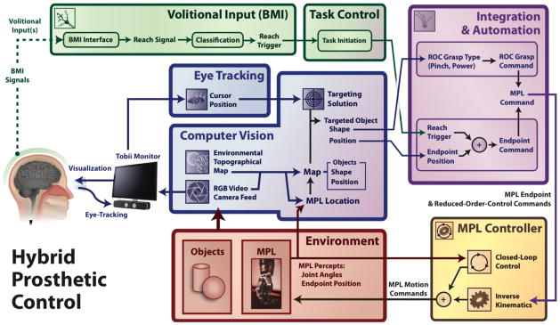
HARMONIE combined BMI system block diagram. The components of the HARMONIE BMI system work together to allow the patient to perform a complex automated motor task. A patient implanted with iEEG electrodes is able to use eye tracking to visually select an object that has been segmented by computer vision. The patient initiates the task via their iEEG-BMI input. The task initiation and object information are used to control the MPL to perform the task.
Fig. 2.

Schematic of the HARMONIE experimental setup. The patient views a segmented scene sent from the computer vision device. The Kinect sensor records both the depth information and RGB of the experimental workspace. The patient’s gaze is recorded by monitor-mounted eye tracking and movement intention is detected by iEEG-based BMI. The MPL carries out the reach, grasp, and place motor task.
II. Methods
A. Subject Info
Two subjects were implanted with subdural ECoG arrays and/or penetrating depth electrodes (Adtech; Racine, WI) for recording seizures prior to surgical resection to treat medically resistant epilepsy with placement based on clinical needs. The ECoG electrodes had a 2.3-millimeter (mm) diameter exposed recording surface with 10-mm inter-electrode (center-to-center) spacing. The depth electrodes had eight 2.41-mm length (6.5-mm center-to-center spacing) platinum contacts. A macro-micro depth electrode had eight macroelectrodes contacts with 1.57-mm length platinum contacts (5-mm center-to-center spacing), as well as four microelectrodes interposed between each of the five most distal contacts.
Our first subject, Subject 1, was a 42 year old right-handed female with a lesion in her left anterior cingulate gyrus. She was implanted with ECoG electrodes including a double-sided 2 × 8 interhemispheric grid over her left mesial frontal cortex in the interhemispheric fissure (Fig. 3B), as well as three 1 × 8 electrode strips over her left dorsolateral prefrontal cortex, extending to the Sylvain fissure. Our second subject, Subject 2, was a 30 year old right-handed male who had previously undergone partial resection of his right post-central gyrus and superior parietal lobule. He was implanted with seven depth electrodes (one being a macro-micro depth electrode) placed medially in his right hemisphere from anterior to posterior from the pre-motor area back into the motor cortex in pre-central gyrus, as well as sensory areas in post-central gyrus and parietal lobe (Fig. 3D). Neuronavigation, via the Cranial Navigation Application (BrainLab; Westchester, IL), was used during placement of the depth electrodes. The patient also had a 1 × 8 ECoG strip placed over motor and sensory cortices laterally.
Fig. 3.

Neural activation during reaches. Cue-averaged statistically significant high gamma modulations relative to pre-cue periods are plotted in a channel x time raster (A for Subject 1, C for Subject 2) with the median behavioral times marked for movement onset (MO; 696 ms, Subject 1; 909 ms, Subject 2) and target button press (TB; 1193 ms, Subject 1; 2093 ms, Subject 2). Results are aligned relative to the movement audio cue (0 ms), and show 1024 ms of the pre-cue period. The mean modulation across nine 16 ms time bins spanning 112 ms (centered on median movement onset time) is plotted on the patient’s brain reconstruction (B for Subject 1, left hemisphere viewed from medial surface; D for Subject 2, right hemisphere viewed from medial surface); the maximum mean modulation is 105%, with a 25% increase as the threshold for display for Subject 1 (106% maximum, 25% threshold for Subject 2). Inter-hemispheric grid (IHG) ECoG electrodes 18, 19, and 26 (outlined in black boxes) displayed task-related modulations during this time period for Subject 1 (B). Routine electrocortical stimulation caused movements in the right arm at IHG 18 and 26 and stiffening on the right side at IHG 19. Depth electrodes APr 5, ABC 7, ABC 8, and MPP 4 were used for control in Subject 2 (D). Stimulation at APr 7 and 8 (near APr 5) elicited left hand clenching (stimulation not done at APr 5 or other activated electrodes).
Both patients gave informed consent for testing to be done according to a protocol approved by the Institutional Review Board of the Johns Hopkins Medical Institutions. Electrode locations were confirmed by volumetric co-registration of the subject’s pre-implantation MRI with their post-surgical CT using the BioImage Suite [41] (Fig. 3B and 3D).
B. Neural Signal Acquisition
A 128-channel NeuroPort system (BlackRock Microsystems; Salt Lake City, UT) was used for iEEG signal acquisition in parallel with clinical long-term EEG monitoring. During training, the NeuroPort system used a sampling rate of 30 KHz with an analog third-order Butterworth anti-aliasing filter with cutoffs of 0.3 Hz and 7,500 Hz. The NeuroPort system applied a digital low-pass filter with a 250 Hz cutoff (4th order Butterworth) and downsampled data to 1 kHz for streaming over UDP to an experimental computer. Any channels with substantial noise or artifacts, as identified by a clinical neurophysiologist by visual inspection, were excluded from subsequent analyses.
C. Training
The subjects performed reaching and grasping movements (30 each for Subject 1, 50 each for Subject 2) with their right (Subject 1) or left (Subject 2) arms, contralateral to their implants. The subjects were instructed to loosely hold a pneumatic squeeze bulb while resting their hand on a home plate sensor in their lap. When a sound clip instructing “Reach” was played, the subjects reached forward and pushed a target button before returning to the home plate. When the “Grasp” auditory cue was played, the subjects tightly grasped the squeeze bulb. Cues were presented pseudo-randomly. Signals from the audio cue, home plate, target button, and pneumatic air pressure sensor were fed into the analog ports of the NeuroPort system for synchronized recording with the iEEG signals. Subject 2 went through training twice, once for functional localization and a second session after which the BMI model was trained.
D. Functional Localization and Neural Signal Analysis
Electrodes that displayed significant task-related high gamma modulation for reach-related activity were identified using a custom analysis script in MATLAB (Mathworks; Natick, MA). The Hilbert transform was calculated on common average referenced (CAR) iEEG data in 128 ms windows (112 ms overlap); this signal was binned in the time domain by averaging 16 adjacent samples at 1000 Hz for an effective time resolution of 16 ms. The Hilbert transform was augmented with a multiplication of the frequency spectrum by a flat-top Gaussian spanning 70–110 Hz to yield an estimate of the high gamma analytic amplitude.
A baseline distribution of high gamma amplitudes was created for each channel by pooling amplitude measurements from the 1024 ms prior to the audio cue. For each channel, separate distributions were created for each time bin after the audio cue. Significant modulations of high gamma amplitude at each channel were found by applying a two-sample t test between each post-stimulus distribution (i.e., one for each time and channel pair) and the baseline distribution. A significance threshold of alpha = 0.05 was used, with corrections for multiple comparisons carried out using the false discovery rate (FDR) correction within each channel. Significant modulations were plotted on a channel vs. time raster and also on the patient’s brain reconstruction to visually determine which electrode locations displayed the greatest task-related activity (Fig. 3A and 3C).
E. BMI Model Training
The results from the aforementioned reaching trial analyses were used to select the electrodes and temporal windows to be used for training the BMI model. The electrodes were selected using a system optimized for rapid event-related feature extraction and statistical testing in order to capture complete spatial-temporal maps of cortical activation. These methods were not optimal for the real-time control of the HARMONIE system. Instead, the Burg algorithm was used to estimate the spectral power of the recorded iEEG signal with a 16th order autoregressive model [42]; an estimate of the high gamma log-power was obtained for each window by computing the mean of the log-transformed spectral power in bins between 72.5 and 110 Hz for each electrode. This frequency band was chosen to capture high gamma modulation while avoiding 60 and 120 Hz noise.
Distributions of high gamma log-power during the active (i.e., ‘related to moving’) and baseline periods were built using 400 ms windows spaced every 100 ms. For Subject 1, windows centered at times between 1800 ms and 1200 ms before onset of the audio cue were used as model inputs representing baseline. The active distribution was built from the 600 ms surrounding (i.e., 300 ms before to 300 ms after) the onset of movement, as detected by the release of the home-plate. This time period was chosen as it displayed robust high-gamma activation during preliminary analysis of the training data used to train the decoder. For Subject 2, the baseline distribution was built from windows whose centers fell in the 1024 ms prior to the audio cue of each trial. The active distribution was built from windows whose centers were between movement onset and movement offset, as detected by the home plate. This change in the baseline and active distributions used was implemented to increase consistency with our functional localization methods (see Methods D). For Subject 2 only, the trained reach classifier was also augmented with additional “baseline” points from periods where only grasping movements were being made, in an attempt to isolate features responsible for reaching only.
The high gamma log-power distributions during baseline and active periods were then used as signal features to train a binary linear discriminant analysis (LDA) classifier, which was employed online to detect reaching movements. In Subject 2, transition probabilities were modulated heuristically to help the time course of classifications approach that of the true movements. This was done a priori (before the testing sessions), with values of 0.95 for the probability of staying at rest if currently at rest (0.05 for entering an active period), and 0.8 for the probability of remaining active if currently active (0.2 for returning to rest).
F. Testing Paradigm
A video monitor mounted with a portable Tobii PCEye (Tobii Technology; Stockholm, Sweden) eye tracking sensor was placed in front of each subject (Fig. 2). This monitor displayed video from a workspace adjacent to the subject that consisted of objects (one ball for Subject 1, three for Subject 2) placed on a table positioned in front of the MPL and computer vision system. Subjects were able to control, via eye tracking, a cursor displayed on the monitor in order to select objects in the video. For Subject 1, the reach trials were not cued and the subject decided when to initiate reach movements after the ball was placed in the workspace. For Subject 2, trials were cued by the experimenter. The experimenter would wait for Subject 2 to focus on a home area of the screen before indicating which of the three colored balls he should select. At the onset of each trial, the subject was instructed to visually fixate on the ball displayed on the monitor and then performing a reach toward the ball on the monitor (though it was possible to reach without proper fixation). When neural signals of reaching, concurrent to visual fixation, were detected, the MPL initiated a complex sequence of actions consisting of reaching, grasping, picking up, moving, and dropping the ball under computer vision guidance. Subject 1 had 2 blocks of online testing while Subject 2 had one block.
Performance of the HARMONIE system was determined, in part, by video analysis of the testing session. Trials were deemed successful if the patient performed a reaching movement that subsequently initiated the MPL’s motor task (see Online BMI Testing for timing). Additionally, Subject 2 had to select the correct ball from three possibilities for the trial to be considered a success. For Subject 1, each distinct reaching movement toward the monitor by the patient was counted as a separate trial since she was not cued.
G. Computer Vision and Eye Tracking
Computer vision and eye tracking were used for identification and selection of targets in the workspace for MPL action. For computer vision, a Kinect (Microsoft; Redmond, WA) infrared range sensor system array was used to capture 3-D point cloud depth data and RGB video from the subject’s workspace (Fig. 2). The Kinect was placed on a base stand above the MPL, approximating the location of the human head relative to the right upper limb. The Kinect also captured RGB video of the workspace to be viewed by the subject on the computer monitor. The Kinect streamed, via USB 2.0, to a Linux computer running the Robot Operating System (ROS) Fuerte platform (Willow Garage; Menlo Park, CA) (Fig. 1).
Computer vision was used to segment spherical objects. The Point Cloud Library (PCL) was primarily used for 3D processing [43]. A pass-through filter was first applied to remove 3D points outside of the workspace of the MPL. Secondly, a sample consensus algorithm was used to find and segment the largest planar surface in the scene corresponding to the tabletop. A Euclidean clustering extraction algorithm was applied to the 3D points on the tabletop to assign groups of points to an object in an unsupervised fashion [44]. A sample consensus algorithm was then applied to each of the objects to determine if the object corresponded to a sphere or cylinder. The output from this classification also included geometric properties of the object, including the radius and orientation. These object properties assisted in selecting optimal grasp types for interacting with the object. The RGB video and object parameters (shape and position relative to the MPL) identified by the ROS system were streamed over UDP from the Linux machine to a computer controlling the monitor in front of the subject.
The RGB video from the Kinect was displayed on the monitor in front of the subject utilizing a MATLAB graphical user interface (GUI). Spherical objects successfully identified through segmentation of the point cloud were outlined in the RGB visualization on the monitor by a light grey circle. The Tobii PCEye eye tracker mounted at the base of the monitor allowed the user to control the mouse cursor on the monitor with their gaze position alone.
Visual feedback was provided to the patient through the GUI to indicate successful eye tracking and iEEG-based initiation by changing the color of the highlighting circle surrounding the segmented object. When the eye-tracker-controlled cursor was not over the object, the circle outlining the object was grey. For Subject 1, when the cursor was within a distance of twice the object’s radius from its center, the circle changed to red to indicate successful fixation. This feedback was modified for Subject 2 due to possible overlap of extending the radius with multiple objects in the workspace. For Subject 2, when the cursor was within the actual radius of the object, the circle changed from grey to blue to indicate successful fixation.
If an intended reach signal was detected by iEEG while the circle was fixated upon, the system entered the MPL actuation state and the circle turned green (for both subjects). Upon entering the actuation state the MPL began its action sequence to grasp, pick up, move the selected object, and drop it into a container. Upon completion of the action sequence, the MPL returned to its home position. For Subject 1, the monitor froze on the display frame during the MPL action while for Subject 2 it constantly streamed video of the MPL action. If an intended reach was detected from the iEEG and the subject’s gaze was not yet over an object, the subject had two seconds to look at an object before the command was ignored.
We performed offline testing of the computer vision module after system improvements were made for Subject 2. We recorded 200 video frames with different types of objects while varying the number and placement of the objects in the workspace. We investigated the number of frames each object was identified in, as well as the variability in their measured sizes and positions. This was done in addition to tracking computer vision errors during online testing.
H. Modular Prosthetic Limb
The MPL is an anthropomorphic robotic limb with 17 controllable DOF and 26 articulating DOF [4]. The MPL software architecture and control system allows for high-level commands, e.g. those translated from neural signals [5], to actuate a coordinated sequence of movements [45]. Endpoint Control (EP) and Reduced Order Control (ROC) commands allow developers to specify three-dimensional hand end-point positions, velocities, and grasp patterns. The sequence of EP and ROC commands given can be determined by the shape and position of the objects in the workspace. A Jacobian-based algorithm is then employed to find the inverse-kinematics needed to execute the specified motor task.
A right-handed MPL was attached on the right side of the same stand and base used to mount the Kinect (Fig. 2). This corresponded to the limb controlled by the contralateral (left-sided) supplementary motor area recorded with ECoG for Subject 1. The right-handed MPL was ipsilateral to the patient’s right-sided implant in Subject 2; therefore the arm was positioned facing the subject in such a way to mirror his left hand. The same object was used repeatedly for Subject 1 while several objects of varying consistency and texture were used with Subject 2.
The object position and shape derived from computer vision and selected with eye tracking were translated into MPL EP and ROC commands (Fig. 1). These commands were sent to the MPL controller and inverse kinematics were used to determine MPL motion commands. The object used with Subject 1 was placed on a pedestal (small roll of tape) to stabilize and elevate the ball to help the MPL pick it up (similar to [6]) while no pedestals were used with the multiple objects for Subject 2.
The path-planning module calculated the final hand position, orientation, and grasp type based on the object type and orientation in the workspace. Standard inverse kinematic techniques [46] were then used to calculate target joint angles for the arm and wrist to achieve the target hand position and orientation, with the additional degree of freedom in the arm used to minimize the elbow position. Additional waypoints were added to the target trajectory to control the direction of approach, and their joint angle representations were also estimated using inverse kinematics. The target waypoints, converted to joint space, were used to generate and stream more continuous intermediate joint commands to the MPL via linear interpolation.
I. Online BMI Testing
The HARMONIE system was tested online with the patient two days (Subject 1) and one day (Subject 2) after the training session with the patient. For online BMI control, signals were streamed and processed and the high gamma activation in the selected electrodes was calculated with the same parameters as the training data. High gamma log-power calculations were done as in the training set on 400 ms windows in real time with a median time of 12 ms between iterations for Subject 1 and 31 ms for Subject 2. Each power calculation was used as an input to the LDA classifier constructed from the training data. To reduce spurious classifications, the LDA model had to return a positive classification for each time point within a 500 ms window. Once a movement was detected, the system was flagged for two seconds to initiate a reach if an object was visually selected in this timeframe and the MPL was not already moving. Classifications by the LDA then resumed after these two seconds, and the arm could be flagged to move again once another 500 ms of data was collected and processed.
Offline analysis of the HARMONIE system was performed by synchronizing the recorded NeuroPort data and clinical monitoring video. To assess the sensitivity and specificity of the BMI movement detection, active and baseline periods based on movement off of the home plate (i.e., reach onset) were analyzed. Trials in which the system predicted a movement between 500 ms before and 3000 ms after the subject’s hand left the home plate were denoted as a true positive (Fig. 4A). This time window was selected to reflect pre-cue activity and the median reach duration observed in the training set (Fig. 4). The movement prediction sensitivity was defined as the percent of trials detected as true positives. Movement of the MPL was initiated immediately upon an iEEG movement detection; the true positive window was used only for offline accuracy analysis.
Fig. 4.

Four trial types of the HARMONIE system are shown. Blue lines represent the actual movement of Subject 1’s right hand, with an upward deflection marking the trial start (i.e., reach onset) when the subject lifted their hand off the home plate (zeroed when resting). Red stars demonstrate actual BMI prediction of a movement for Subject 1. The red filled areas represent the baseline window where no movement detections were expected, and the green areas represent time windows where we expect movement detections as a result of reach onset. (A) and (B) are representative of the successful trials; there was typically either just one prediction at the onset of movement or there was a second prediction at a later time during the movement. (C) shows an example of a trial where the baseline was discarded due to contamination from a previous movement. This baseline was therefore not included in our accuracy analysis, but the uncontaminated active period surrounding movement onset was. (D) depicts a trial where both the baseline and the active period were classified incorrectly, resulting in a false positive and false negative
The true negative rate was found by looking at a baseline period of 3500 ms (i.e., equal in duration to the active period) ending 500 ms before movement onset. If no classifications were made during the baseline period, it was counted as a true negative. The percent of baseline periods which were counted as true negatives was then defined as the movement prediction specificity. Baseline periods were excluded from consideration if the subject moved within 1000 ms before the baseline began. We then verified that none of the remaining baselines had a movement classification within 2500 ms before its start. This was done since a classification event would cause the system to pause detection for two seconds, in addition to the 500 ms of positive classifications required for a detection.
The false positive rate was determined by analyzing all periods of time during testing where the subject’s arms were at rest for at least one minute. This included time during which the MPL was moving and the subject interacted with experimenters. The false positive rate was calculated as the total number of movement classifications during the rest blocks divided by the total duration of the rest blocks.
III. Results
The HARMONIE system allowed both subjects to perform complex object manipulations with the MPL using only eye gaze and iEEG signals corresponding to natural reaching movements (Supplemental Video 1). Subject 2 was able to choose among three balls to successfully power the HARMONIE with improvement in task completion time (Supplemental Video 2). Control of movement initiation was activated by contralateral reaches but not by an ipsilateral reach when tested with Subject 1 (Supplemental Video 3).
A. Online Global Evaluation
The subjects attempted 28 self-paced trials (Subject 1) and 31 cued trials (Subject 2) over the course of an hour long testing session (for each subject). Trials were deemed global system successes if combined eye-tracking and reach initiated the MPL to complete the entire reach-grasp-and-drop task with one ball (Subject 1) or three balls (Subject 2).
For Subject 1, the testing session was divided into two blocks: a block of 18 reaches where the subject’s movements were recorded via the home plate, and a block of 10 reaches with no home plate recordings. Trials of the BMI system initiated by movement toward the monitor were successful during the first block in 14 of the 18 attempts (77.8% system success rate). The success rate of the system decreased to 20 of 28 (71.4%) attempts by the subject when trials from the second block were added. For the 28 trials, four of the eight system failures were traced to failure to classify the iEEG signal, and three of the errors were traced back to eye tracking. Identification of false positives in the second block was not possible due to a lack of movement timing information from the home plate (it was not in use). In one case, the patient attempted an identical reach with her ipsilateral arm (neurologically inappropriate for implant site) and failed to trigger the system. The patient subsequently reached with her contralateral arm and successfully triggered the HARMONIE system.
For Subject 2, 21 of the 31 trials led to successful completion of the entire system (67.7% system success rate). Of the 10 global system failures, nine were traced back to failure of the MPL and computer vision system to pick up the ball. Failure of one trial was traced back to an inability classify movement from the iEEG signal. The patient had trouble remaining in the visual home area after being cued to ball type but before the “Go” cue was given. For the 11 trials in which he adequately waited for the cue and the data could be synced, there was a median 3.55 seconds delay between cue and system initiation.
B. iEEG-Based Decoding Evaluation
Initiation of movement was determined by the iEEG portion of the hybrid BMI using an LDA decoding model based on a training session two days prior to the testing session for Subject 1 and one day prior for Subject 2. During the training session, three electrodes located over the supplementary motor area (SMA) of Subject 1 (Fig. 3B) showed robust high gamma activation for a substantial duration near the onset of reaches. Subject 2 also demonstrated similar patterns of activity in four contacts in three depth electrodes located within hand motor and sensory cortices, as well as the inferior parietal lobe (Fig. 3D). Only trials where the subject’s movement was adequately recorded via the home plate were used for iEEG analysis.
For Subject 1, of the 18 trials considered, 16 were detected by the system, resulting in a movement prediction sensitivity of 88.9% (Fig. 4A). 15 of these trials had baselines uncontaminated by previous movements. A false positive classification was made during one of these baselines, yielding a specificity of 93.3%. Therefore, the balanced accuracy of the iEEG-based movement prediction module (i.e., the mean of the specificity and sensitivity, see Online BMI Testing) was 91.1%. We then calculated the chance prediction accuracy while accounting for the pacing of our movement predictions. We shuffled the intervals between movement predictions 10,000 times and computed the balanced accuracies on these shuffled predictions with trial timing held constant. The 95th percentile of these shuffled accuracies was chosen as the α = 0.05 significance threshold. The shuffled dataset had a median accuracy of 51.7% and a significance threshold of 61.1%. Therefore, the original balanced classification accuracy of 91.1% was significantly higher than chance (p< 0.05). In trials where the movement was accurately predicted, the median latency of the prediction relative to the detection of their movement onset was 200 ms. In order to quantify the rate of false positives made by the iEEG module, we identified nine contiguous blocks of time where the subject rested their arms for at least one minute. During the 13.2 minutes of rest time, the iEEG module made 14 false positive classifications, resulting in an average rate of 1.06 iEEG-only based false positives per minute.
For Subject 2, 28 of the 31 trials were considered, with 3 dropped due to technical failure of the home plate. Of the 28 trials considered, 24 were detected by the system, resulting in a movement prediction sensitivity of 85.7%. The baseline intervals were uncontaminated by previous movements in 27 of the 28 trials. No false positive classifications were made during these baseline intervals, yielding a specificity of 100%. This yielded a balanced accuracy of 92.9%, significant (p<0.05) with a threshold shuffled accuracy of 57.1% and a median shuffled accuracy of 51.4%. The median time between movements and their iEEG prediction was 273 ms. The false positive rates were calculated as above and demonstrated three false positives over 14.7 minutes of rest time, resulting in 0.20 false positives per minute for the iEEG module.
C. Computer Vision and Eye Tracking
During online testing, the computer vision reliably segmented spheres (one object for Subject 1, three for Subject 2) with radii of 4.7 centimeters (cm) throughout a workspace measuring 66 × 45 cm. When computer vision was tested offline with the ball used for Subject 1, the ball was correctly identified in all 200 recorded frames. The range of predictions of the ball’s radius ranged between 4.51 and 4.60 cm. The object’s 3D position varied at most by 0.14 cm.
We also investigated how closely two objects could be positioned next to each other. We found that two tennis balls with radii of 3.35 cm could be reliably detected (both objects accurately detected in 196/200 frames) when separated by just 2.5 cm. Their detected radii varied between 3.52 and 3.99 cm and their positions varied by at most 0.17 cm.
The computer vision reliably detected a large number of objects simultaneously. When three tennis balls were well spaced in the workspace (21.59 to 24.28 cm between each object as measured by the system; similar to the set up for Subject 2), the system accurately detected all the objects in 196/200 frames. When eight objects of various size and material were placed in the workspace, the system simultaneously detected all eight of the objects in 192/200 frames (Fig. 5A). Of the objects tested, the system detected balls of radii ranging 3.35 to 12 cm.
Fig. 5.
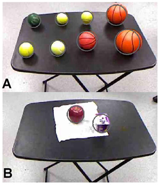
Offline demonstration of computer vision segmentation ability. Grey circles depict the system’s predicted size and location for each object. (A) shows that the object recognition software was able to simultaneously segment out eight spherical objects of varying sizes and materials. During online testing with the subject, only a single rubber basketball was used. (B) shows the potential for the system to segment out everyday lunch objects, such as an apple and a cup of yogurt.
Subject 1 used eye tracking to select the objects with a moderate amount of difficulty. To minimize subject eye strain, the minimal selectable area for hovering the cursor to perform a selection was doubled from the original radius size. For Subject 1, three of the seven total system errors were due to eye tracking difficulties causing the object to not be selected.
Subject 2 demonstrated robust control over the eye tracking system (without subsequent improvements). He was able to visually select the correct ball (indicated by color) out of three objects 100% of the time. No global system errors were attributed to the eye tracking in this subject. For the 13 trials in which the subject maintained fixation within the home area until the go cue was given, the subject was consistently able to select the correct object within approximately one to two seconds of the cue.
D. Modular Prosthetic Limb Control
Once initiated by the combined iEEG and eye control-based BMI, the MPL performed the complex reach-grasp-and-drop task 100% of the time for Subject 1 and 70% of the time for Subject 2. As mentioned above, Subject 2 used three balls with varying textures and, unlike Subject 1, the objects were not placed on pedestals. For Subject 1, the mean time from task initiation to ball drop was 22.3 seconds with a range not appreciable at our monitor’s frame rate (less than 0.1 seconds). Improvements to the MPL control system trajectory planning algorithms led to shorter completion times for Subject 2, with a mean completion time of approximately 12.2 seconds and a similar range of less than 0.1 seconds (an improvement of 45.3%).
IV. Discussion
The present study demonstrates that the final version of the HARMONIE system reliably and accurately combined eye tracking, computer vision, iEEG BMI, and advanced robotics cohesively to perform complex interactions between the MPL and a real object in cued and un-cued trials. To our knowledge this is the first demonstration of a semi-autonomous hybrid BMI system using intracranial signals from humans. The success of this demonstration is due to the combination of supervisory control, hybrid BMI, and intelligent robotics.
The HARMONIE system uses a supervisory control strategy to allow patients to perform a complex motor task with the MPL. Supervisory control strategies range from high-level (goal oriented) control to low-level (direct manipulation or process oriented) control. We focused on the patient’s intention to initiate the task (high-level) with a reach. The HARMONIE system performed well using supervisory control and successfully performed the complex motor task 71.4% and 67.7% of the time in two subjects. The median iEEG movement detection delays were only 200 ms and 273 ms. An important benefit of high-level control is that once initiated, the robotic actuator can proceed autonomously, thus freeing the patient from the sustained attention necessary to continuously control the many DOF of the MPL during a complex motor task.
In the online demonstration, the HARMONIE system was able to integrate information from both the patient and environment to successfully determine the unique path the MPL took for each trial. The robotic limb performed the entire complex task 100% (Subject 1) and 70% (Subject 2) of the time after initiation with a mean completion time of 22.3 seconds and 12.2 seconds respectively, both with a range of less than 0.1s. The decrease in MPL success for the second subject may be attributed to more challenging and realistic conditions, i.e. adding two additional objects and not using a pedestal to elevate and stabilize the objects. The semi-autonomous control framework enabled rapid implementation of modular improvements. For example, improvements in MPL movement transitions resulted in a reduction in completion time during subsequent testing with Subject 2 to 12.2 seconds, a 45.3% improvement (Supplemental Video 2). Our results demonstrate how high-level control enables the patient to complete a complex motor task with semi-autonomous components (the MPL) thereby freeing the patient to concentrate on other matters while the highly reliably prosthetic performs the action.
High-level control stands in contrast to low-level control, or direct manipulation. Work done in humans has demonstrated high-DOF control of robotic actuators with intracortical MEAs [6], [8]. While this strategy requires sustained attention by the patient, the degree of control is generalizable to multiple tasks. Recent work done with MEAs implanted in a paralyzed patient demonstrated control of the MPL to complete a task similar to our experimental setup of reaching to a spherical object and placing it [6]. In Collinger et al.’s study, the average time to task completion was 15.4 seconds (quicker than our Subject 1, slower than Subject 2). However, the range of completion times was 18.4 seconds for their direct control, while ours was less than 0.1s (a benefit of the robotic control in semi-autonomous planning). The ability of the patient implanted with an MEA to use the same BMI approach for several other tasks demonstrates the generalizability of direct manipulation. However, one of the main benefits of mixed supervisory and shared control systems is the flexibility by which they can incorporate both high-level and low-level control. Future development of the HARMONIE system is expected to incorporate both levels of control into its system architecture. This will allow patients to choose when to directly manipulate an object vs. choosing high-level control with less cognitive burden. High-level control can also be used in this scenario to immediately provide a patient with provisional BMI control of common, functionally useful tasks while they engage in training with the BMI to achieve and maintain direct manipulation.
In addition to supervisory control strategies, the use of a hybrid BMI is integral to the success of the HARMONIE system. Two goals of hybrid BMIs are to decrease the number of false positives and to utilize a second input signal for natural control that complements the primary input modality. Implementing assistive BMIs in the real world requires minimizing the number of false positives since each false positive can initiate complex and long tasks. The hybrid portion of the HARMONIE system prevented the acceptable [15] (but still high) baseline iEEG-based false positives from Subjects 1 and 2 (1.06 and 0.2 false positives a minute, respectively) from initiating the system. Only one iEEG-BMI false positive led to a full system initiation once eye-tracking was added to the hybrid BMI. This reduction in false positives is an important benefit of the hybrid BMI approach and of importance when implementing BMIs in real world situations.
An important consideration when using hybrid BMIs is the choice of primary and secondary input modalities. The primary input modality should be a brain signal that can be reliably measured and classified. Our study illustrates the ease and stability of using an iEEG-based BMI since our subjects trained only once with a limited number of trials. Similar to other recent ECoG-based BMI work [7], we were able to use the same model reliably (91.1% and 92.9% balanced accuracy, p<0.05 compared with chance) one and two days later, respectively, indicating stability of the ECoG and depth electrode signals over time. This is in contrast to MEA studies where retraining occurs daily to account for unit dropout over time [6], [8], therefore requiring subsequent recalibration of the BMI system [6]. A possible solution, mentioned above, is to combine MEA and iEEG recording modalities. In this setup, a stable iEEG signal could be decoded for high-level control whenever the MEA-based BMI requires retraining.
One possible drawback of the study is the use of actual, instead of imagined, reaching movements by the patient. Several EEG-based combined assistive systems use combinations of SSVEP, P300 or repetitive, arbitrarily-mapped motor imagery to power their BMIs [16], [35], [36], [39]. While these modalities have been demonstrated to work with paralyzed patients, they can be associated with cognitive fatigue and eye strain [47], [48]. Also, relative to paralyzed patients, patients with intact motor function have decreased neural activity during motor imagery [49], [50], perhaps due to the need to inhibit movement of the native limb. We believe the actual reaches performed by our patients served as a reasonably good analogue for paralyzed patients attempting to move. We focused on movement-induced iEEG responses in the supplementary motor area (Subject 1) and motor and pre-motor cortices (Subject 2), making it highly unlikely that our BMI was reliant on sensory feedback that would not be present in the intended patient population. Future studies could focus on pre-movement activation as another means of controlling for sensory interference in active movements [51]. Further research must be done to quantify the accuracy of iEEG motor intention-based BMIs in appropriate patient populations to control the HARMONIE system.
The purpose of secondary inputs into a hybrid BMI is to complement the primary brain-derived signal. Our study corroborates recent reports showing that the combination of eye tracking with brain control in a hybrid BMI approach improves upon traditional eye tracking assistive devices [15], [16]. Using eye tracking as part of the physiological hybrid BMI leverages patients’ natural ability to use eye gaze to indicate the location of an object relative to the patient. However, eye tracking is also subject to false positives that can interfere with everyday use. Indeed, this is an important motivation for using iEEG and not eye-tracking or P-300-based object selection alone. When visual fixation is used alone, there is a risk of the “Midas Touch” problem, in which fixation on an object (without intent to manipulate it) inadvertently triggers its selection and manipulation [15]. Traditional eye tracking systems have used dwell times for object selection, but users have indicated a preference for BMI object selection [19]. The eye tracking, object recognition, and motor BMI-LDA based selection solution that we used solves the false positive “Midas Touch” problem. Our patients demonstrated adequate control of the eye tracking system with three and zero of the total system errors due to a lack of object fixation before reach initiation. Subject 2 demonstrated robust control of the eye tracking, selecting from the correct of three objects in 100% of trials within approximately 1 to 2 seconds of the cue being given. Subject 1 may have had more difficulty with the eye tracking due to her use of glasses and light eye color. Our 71.4% and 67.7% global system success rate is similar to other hybrid BMI and eye control studies that demonstrated 74.5% correct selection [20] and demonstrate the patients’ natural control of the eye tracking and BMI selection scheme.
The hybrid BMI was able to perform a complex motor task with the aid of intelligent robotics. Objects were identified from a segmented point cloud using computer vision [21], [52], [53] and acted upon by the MPL. Each successful trial required the HARMONIE system to integrate the object’s endpoint position and shape determined by computer vision into a sequence of low-level command necessary to reach, grasp, and drop. Testing with Subject 1 was done with one object while testing with Subject 2 used three objects, with offline testing demonstrating capability of up to eight objects (Fig. 5A). One to three objects could be segmented in 196/200 frames that only decreased to 192/200 frames when eight objects of various sizes (range of 3.35 to 12 cm) were added. A reliable and robust computer vision system further reduces the possibility of false positives by limiting selectable objects in the workspace to only those that should or could be acted upon (as opposed to every object on a monitor). While these results demonstrate the capability of the HARMONIE system, more robust computer vision is needed for the HARMONIE system to perform in the real world, outside of carefully controlled laboratory settings (Fig. 5B). Future work incorporating a second Kinect or other IR depth sensors could allow for more robust identification of a wider variety of objects.
The present study offers a proof of principle of the HARMONIE system, a first time demonstration of a semi-autonomous, iEEG-based, hybrid BMI in human patients. The unique combination of these modalities allowed two patients to intuitively control a complex motor task consisting of reaching, grasping, and dropping an object. Future work will focus on testing the system in a larger pool of patients, both healthy and paralyzed. Modular improvements in the system are expected to achieve quicker and more reliable control.
A major limitation of our pilot system is that the current HARMONIE system shares only a limited amount of control with the user via eye tracking and iEEG. Currently, the system is semi-autonomous and once the iEEG initiation step is completed, the MPL proceeds autonomously with the task. Future work will aim to incorporate true shared control as demonstrated in wheelchair guidance [33] and in a continuous manner [28], building on previous efforts from our team demonstrating online control of continuous reach and grasp of the MPL [5].
In its current form other simple communication interfaces, such as eye tracking alone or P300 or SSVEP-based EEG systems, could initiate the system as well. However, the demonstration of a working system using iEEG is integral to future development. For example, it has been shown that three dimensions of continuous control can be decoded from iEEG [54]. Incorporating this kind of control into our intelligent robotic system will eventually allow for useful continuous shared control of the robotic tasks, allowing the user to control the progression of the arm forward and back through a trajectory constantly updated from information from the environment. Continuous monitoring of error-related neural responses found in iEEG signals could also be used to modify or reset arm positions as necessary [55].
Elucidating a larger repertoire of neural responses will allow for a wider variety of high-level commands to be implemented, leading to a greater number of functional tasks that can be performed with objects. The current system could also be modified to allow the user to select the desired location to place the object by using eye tracking to indicate location and iEEG initiation to begin the placement. As with reaching and grasping in the current system, it is likely that a hybrid combination of iEEG and eye-tracking will provide users with a high degree of flexible yet accurate control over object manipulation and task execution.
The HARMONIE system, using the aforementioned and future improvements in relevant technologies, will allow patients to achieve useful and reliable control of an advanced multi-DOF powered robotic upper limb without extensive training and with minimal cognitive load.
Supplementary Material
Acknowledgments
Data analysis and online control were supported in part by the National Institute of Neurological Disorders and Stroke under Grant 3R01NS0405956-09S1, by DARPA under contract 19GM-1088724, and by the National Institute of Biomedical Imaging and Bioengineering under Grant 5T32EB003383-08. The MPL was developed with funds from DARPA under contract No. N66001-10-C-4056. David McMullen was a Howard Hughes Medical Institute Research Fellow.
Contributor Information
David P. McMullen, Department of Neurosurgery, Johns Hopkins University, Baltimore, MD 21205 USA.
Guy Hotson, Department of Electrical and Computer Engineering, Johns Hopkins University, Baltimore, MD 21218 USA.
Kapil D. Katyal, Research and Exploratory Development division of the Johns Hopkins University Applied Physics Laboratory, Laurel, MD 20723 USA.
Brock A. Wester, Research and Exploratory Development division of the Johns Hopkins University Applied Physics Laboratory, Laurel, MD 20723 USA.
Matthew S. Fifer, Email: msfifer@gmail.com, Department of Biomedical Engineering, Johns Hopkins University, Baltimore, MD 21205 USA.
Timothy G. McGee, Research and Exploratory Development division of the Johns Hopkins University Applied Physics Laboratory, Laurel, MD 20723 USA
Andrew Harris, Research and Exploratory Development division of the Johns Hopkins University Applied Physics Laboratory, Laurel, MD 20723 USA.
Matthew S. Johannes, Research and Exploratory Development division of the Johns Hopkins University Applied Physics Laboratory, Laurel, MD 20723 USA.
R. Jacob Vogelstein, Research and Exploratory Development division of the Johns Hopkins University Applied Physics Laboratory, Laurel, MD 20723 USA.
Alan D. Ravitz, Research and Exploratory Development division of the Johns Hopkins University Applied Physics Laboratory, Laurel, MD 20723 USA.
William S. Anderson, Department of Neurosurgery, Johns Hopkins University, Baltimore, MD 21287 USA
Nitish V. Thakor, Department of Biomedical Engineering, Johns Hopkins University, Baltimore, MD 21205 USA. SINAPSE Institute at the National University of Singapore in Singapore, SG.
Nathan E. Crone, Department of Neurology, Johns Hopkins University, Baltimore, MD 21205 USA.
References
- 1.Nobunaga AI, Go BK, Karunas RB. Recent demographic and injury trends in people served by the Model Spinal Cord Injury Care Systems. Arch Phys Med Rehabil. 1999 Nov;80(11):1372–1382. doi: 10.1016/s0003-9993(99)90247-2. [DOI] [PubMed] [Google Scholar]
- 2.Cao Y, Chen Y, DeVivo M. Lifetime Direct Costs After Spinal Cord Injury. Topics in Spinal Cord Injury Rehabilitation. 2011 Mar;16(4):10–16. [Google Scholar]
- 3.Zickler C, Di Donna V, Kaiser V, Al-Khodairy A, Kleih SC, Kübler A. BCI applications for people with disabilities: Defining user needs and user requirements. Assistive Technology from Adapted Equipment to Inclusive Environments: AAATE. 2009;25:185–189. [Google Scholar]
- 4.Johannes MS, Bigelow JD, Burck JM, Harshbarger SD, Kozlowski MV, Van Doren T. An overview of the developmental process for the modular prosthetic limb. Johns Hopkins APL Technical Digest. 2011;30(3):207–216. [Google Scholar]
- 5.Fifer MS, Hotson G, Wester BA, McMullen DP, Wang Y, Johannes MS, Katyal KD, Helder JB, Para MP, Vogelstein RJ, Anderson WS, Thakor NV, Crone NE. IEEE Transactions on Neural Systems and Rehabilitation Engineering. 2013. Simultaneous Neural Control of Simple Reaching and Grasping with the Modular Prosthetic Limb using Intracranial EEG. vol. Early Access Online. [DOI] [PMC free article] [PubMed] [Google Scholar]
- 6.Collinger JL, Wodlinger B, Downey JE, Wang W, Tyler-Kabara EC, Weber DJ, McMorland AJC, Velliste M, Boninger ML, Schwartz AB. High-performance neuroprosthetic control by an individual with tetraplegia. Lancet. 2013 Feb;381(9866):557–564. doi: 10.1016/S0140-6736(12)61816-9. [DOI] [PMC free article] [PubMed] [Google Scholar]
- 7.Wang W, Collinger JL, Degenhart AD, Tyler-Kabara EC, Schwartz AB, Moran DW, Weber DJ, Wodlinger B, Vinjamuri RK, Ashmore RC, Kelly JW, Boninger ML. An Electrocorticographic Brain Interface in an Individual with Tetraplegia. PLoS ONE. 2013 Feb;8(2):e55344. doi: 10.1371/journal.pone.0055344. [DOI] [PMC free article] [PubMed] [Google Scholar]
- 8.Hochberg LR, Bacher D, Jarosiewicz B, Masse NY, Simeral JD, Vogel J, Haddadin S, Liu J, Cash SS, van der Smagt P, Donoghue JP. Reach and grasp by people with tetraplegia using a neurally controlled robotic arm. Nature. 2012 May;485(7398):372–375. doi: 10.1038/nature11076. [DOI] [PMC free article] [PubMed] [Google Scholar]
- 9.Simeral JD, Kim SP, Black MJ, Donoghue JP, Hochberg LR. Neural control of cursor trajectory and click by a human with tetraplegia 1000 days after implant of an intracortical microelectrode array. J Neural Eng. 2011 Apr;8(2):025027. doi: 10.1088/1741-2560/8/2/025027. [DOI] [PMC free article] [PubMed] [Google Scholar]
- 10.Leuthardt EC, Miller KJ, Schalk G, Rao RPN, Ojemann JG. Electrocorticography-based brain computer Interface-the seattle experience. IEEE Transactions on Neural Systems and Rehabilitation Engineering. 2006 Jun;14(2):194–198. doi: 10.1109/TNSRE.2006.875536. [DOI] [PubMed] [Google Scholar]
- 11.Yanagisawa T, Hirata M, Saitoh Y, Kishima H, Matsushita K, Goto T, Fukuma R, Yokoi H, Kamitani Y, Yoshimine T. Electrocorticographic control of a prosthetic arm in paralyzed patients. Annals of Neurology. 2012;71(3):353–361. doi: 10.1002/ana.22613. [DOI] [PubMed] [Google Scholar]
- 12.Vadera S, Marathe AR, Gonzalez-Martinez J, Taylor DM. Stereoelectroencephalography for continuous two-dimensional cursor control in a brain-machine interface. Neurosurgical Focus. 2013 Jun;34(6):E3. doi: 10.3171/2013.3.FOCUS1373. [DOI] [PubMed] [Google Scholar]
- 13.Allison BZ, Leeb R, Brunner C, Müller-Putz GR, Bauernfeind G, Kelly JW, Neuper C. Toward smarter BCIs: extending BCIs through hybridization and intelligent control. Journal of Neural Engineering. 2012 Feb;9(1):013001. doi: 10.1088/1741-2560/9/1/013001. [DOI] [PubMed] [Google Scholar]
- 14.Allison BZ, Brunner C, Kaiser V, Müller-Putz GR, Neuper C, Pfurtscheller G. Toward a hybrid brain computer interface based on imagined movement and visual attention. J Neural Eng. 2010 Apr;7(2):026007. doi: 10.1088/1741-2560/7/2/026007. [DOI] [PubMed] [Google Scholar]
- 15.Pfurtscheller G, Allison BZ, Brunner C, Bauernfeind G, Solis-Escalante T, Scherer R, Zander TO, Mueller-Putz G, Neuper C, Birbaumer N. The Hybrid BCI. Front Neurosci. 2010 Apr;4:30. doi: 10.3389/fnpro.2010.00003. [DOI] [PMC free article] [PubMed] [Google Scholar]
- 16.Pfurtscheller G, Solis-Escalante T, Ortner R, Linortner P, Muller-Putz GR. Self-Paced Operation of an SSVEP-Based Orthosis With and Without an Imagery-Based ‘Brain Switch:’; A Feasibility Study Towards a Hybrid BCI. IEEE Transactions on Neural Systems and Rehabilitation Engineering. 2010 Aug;18(4):409–414. doi: 10.1109/TNSRE.2010.2040837. [DOI] [PubMed] [Google Scholar]
- 17.Millán JdR, Rupp R, Müller-Putz GR, Murray-Smith R, Giugliemma C, Tangermann M, Vidaurre C, Cincotti F, Kübler A, Leeb R, Neuper C, Müller K-R, Mattia D. Combining brain computer interfaces and assistive technologies: state-of-the-art and challenges. Front Neurosci. 2010;4:161. doi: 10.3389/fnins.2010.00161. [DOI] [PMC free article] [PubMed] [Google Scholar]
- 18.Kennedy PR, Bakay RAE, Moore MM, Adams K, Goldwaithe J. Direct control of a computer from the human central nervous system. IEEE Transactions on Rehabilitation Engineering. 2000 Jun;8(2):198–202. doi: 10.1109/86.847815. [DOI] [PubMed] [Google Scholar]
- 19.Zander TO, Gaertner M, Kothe C, Vilimek R. Combining Eye Gaze Input With a Brain Computer Interface for Touchless Human Computer Interaction. International Journal of Human-Computer Interaction. 2010;27(1):38–51. [Google Scholar]
- 20.Lee EC, Woo JC, Kim JH, Whang M, Park KR. A brain computer interface method combined with eye tracking for 3D interaction. Journal of Neuroscience Methods. 2010 Jul;190(2):289–298. doi: 10.1016/j.jneumeth.2010.05.008. [DOI] [PubMed] [Google Scholar]
- 21.Frisoli A, Loconsole C, Leonardis D, Banno F, Barsotti M, Chisari C, Bergamasco M. A New Gaze-BCI-Driven Control of an Upper Limb Exoskeleton for Rehabilitation in Real-World Tasks. IEEE Transactions on Systems Man and Cybernetics Part C: Applications and Reviews. 2012;42(6):1169–1179. [Google Scholar]
- 22.Salisbury K. Issues in human/computer control of dexterous remote hands. IEEE Transactions on Aerospace and Electronic Systems. 1988 Sep;24(5):591–596. [Google Scholar]
- 23.Hayati S, Venkataraman ST. Design and implementation of a robot control system with traded and shared control capability. 1989 IEEE International Conference on Robotics and Automation, 1989. Proceedings; 1989. pp. 1310–1315. [Google Scholar]
- 24.Sheridan TB. Telerobotics, Automation, and Human Supervisory Control. MIT Press; 1992. [Google Scholar]
- 25.Flemisch FO, Adams CA, Conway SR, Goodrich KH, Palmer MT, Schutte PC. NASA Technical Report NASA/TM 2003-212672. Dec, 2003. The H-Metaphor as a Guideline for Vehicle Automation and Interaction. [Google Scholar]
- 26.Musallam S, Corneil BD, Greger B, Scherberger H, Andersen RA. Cognitive Control Signals for Neural Prosthetics. Science. 2004 Jul;305(5681):258–262. doi: 10.1126/science.1097938. [DOI] [PubMed] [Google Scholar]
- 27.Goodrich KH, Schutte PC, Flemisch FO, Williams RA. Application of the H-Mode, A Design and Interaction Concept for Highly Automated Vehicles, to Aircraft. 25th Digital Avionics Systems Conference, 2006 IEEE/AIAA; 2006. pp. 1–13. [Google Scholar]
- 28.Kim HK, Biggs J, Schloerb W, Carmena M, Lebedev MA, Nicolelis MAL, Srinivasan MA. Continuous shared control for stabilizing reaching and grasping with brain-machine interfaces. IEEE Transactions on Biomedical Engineering. 2006 Jun;53(6):1164–1173. doi: 10.1109/TBME.2006.870235. [DOI] [PubMed] [Google Scholar]
- 29.Wolpaw JR. Brain computer interfaces as new brain output pathways. The Journal of Physiology. 2007;579(3):613–619. doi: 10.1113/jphysiol.2006.125948. [DOI] [PMC free article] [PubMed] [Google Scholar]
- 30.Galán F, Nuttin M, Lew E, Ferrez PW, Vanacker G, Philips J, del J, Millán R. A brain-actuated wheelchair: Asynchronous and non-invasive Brain computer interfaces for continuous control of robots. Clinical Neurophysiology. 2008 Sep;119(9):2159–2169. doi: 10.1016/j.clinph.2008.06.001. [DOI] [PubMed] [Google Scholar]
- 31.Tonin L, Leeb R, Tavella M, Perdikis S, del R Millán J. The role of shared-control in BCI-based telepresence. 2010 IEEE International Conference on Systems Man and Cybernetics (SMC); 2010. pp. 1462–1466. [Google Scholar]
- 32.Perrin X, Chavarriaga R, Colas F, Siegwart R, del J, Millán R. Brain-coupled interaction for semi-autonomous navigation of an assistive robot. Robotics and Autonomous Systems. 2010 Dec;58(12):1246–1255. [Google Scholar]
- 33.Carlson T, del J, Millan R. Brain-Controlled Wheelchairs: A Robotic Architecture. IEEE Robotics Automation Magazine. 2013;20(1):65–73. [Google Scholar]
- 34.Ivlev O, Martens C, Graeser A. Rehabilitation robots FRIEND-I and FRIEND-II with the dexterous lightweight manipulator. Technology & Disability. 2005 May;17(2):111–123. [Google Scholar]
- 35.Martens C, Prenzel O, Gräser A. The rehabilitation robots FRIEND-I & II: Daily life independency through semi-autonomous task-execution. Rehabilitation Robotics. 2007:137–162. [Google Scholar]
- 36.Onose G, Grozea C, Anghelescu A, Daia C, Sinescu CJ, Ciurea AV, Spircu T, Mirea A, Andone I, Spânu A, Popescu C, Mihăescu A-S, Fazli S, Danóczy M, Popescu F. On the feasibility of using motor imagery EEG-based brain-computer interface in chronic tetraplegics for assistive robotic arm control: a clinical test and long-term post-trial follow-up. Spinal Cord. 2012 Aug;50(8):599–608. doi: 10.1038/sc.2012.14. [DOI] [PubMed] [Google Scholar]
- 37.Royer AS, He B. Goal selection versus process control in a brain computer interface based on sensorimotor rhythms. J Neural Eng. 2009 Feb;6(1):016005. doi: 10.1088/1741-2560/6/1/016005. [DOI] [PMC free article] [PubMed] [Google Scholar]
- 38.Royer AS, Rose ML, He B. Goal selection versus process control while learning to use a brain computer interface. J Neural Eng. 2011 Jun;8(3):036012. doi: 10.1088/1741-2560/8/3/036012. [DOI] [PMC free article] [PubMed] [Google Scholar]
- 39.Iturrate I, Antelis JM, Kubler A, Minguez J. A Noninvasive Brain-Actuated Wheelchair Based on a P300 Neurophysiological Protocol and Automated Navigation. IEEE Transactions on Robotics. 2009 Jun;25(3):614–627. [Google Scholar]
- 40.Escolano C, Antelis JM, Minguez J. A Telepresence Mobile Robot Controlled With a Noninvasive Brain-Computer Interface. IEEE Transactions on Systems Man and Cybernetics Part B: Cybernetics. 2012 Jun;42(3):793–804. doi: 10.1109/TSMCB.2011.2177968. [DOI] [PubMed] [Google Scholar]
- 41.Duncan JS, Papademetris X, Yang J, Jackowski M, Zeng X, Staib LH. Geometric strategies for neuroanatomic analysis from MRI. NeuroImage. 2004;23(Supplement 1):S34–S45. doi: 10.1016/j.neuroimage.2004.07.027. [DOI] [PMC free article] [PubMed] [Google Scholar]
- 42.McFarland DJ, Wolpaw JR. Sensorimotor rhythm-based brain-computer interface (BCI): feature selection by regression improves performance. IEEE Transactions on Neural Systems and Rehabilitation Engineering. 2005;13(3):372–379. doi: 10.1109/TNSRE.2005.848627. [DOI] [PubMed] [Google Scholar]
- 43.Point Cloud Library. [Online]. Available: http://pointclouds.org/
- 44.Rusu RB. PhD Thesis. Technische Universitaet Muenchen, Computer Science Department; Germany: 2009. Semantic 3D Object Maps for Everyday Manipulation in Human Living Environments. [Google Scholar]
- 45.Fifer MS, Acharya S, Benz HL, Mollazadeh M, Crone NE, Thakor NV. Toward Electrocorticographic Control of a Dexterous Upper Limb Prosthesis: Building Brain-Machine Interfaces. IEEE Pulse. 2012;3(1):38–42. doi: 10.1109/MPUL.2011.2175636. [DOI] [PMC free article] [PubMed] [Google Scholar]
- 46.Spong MW. Robot dynamics and control. New York: Wiley; 1989. [Google Scholar]
- 47.Palankar M, De Laurentis KJ, Alqasemi R, Veras E, Dubey R, Arbel Y, Donchin E. Control of a 9-DoF Wheelchair-mounted robotic arm system using a P300 Brain Computer Interface: Initial experiments. IEEE International Conference on Robotics and Biomimetics, 2008. ROBIO 2008; 2009. pp. 348–353. [Google Scholar]
- 48.Graimann B, Allison B, Mandel C, Lüth T, Valbuena D, Gräser A. Robust Intelligent Systems. Springer-Verlag; London: 2008. Non-invasive Brain-Computer Interfaces for Semi-autonomous Assistive Devices; pp. 113–138. [Google Scholar]
- 49.Szameitat AJ, Shen S, Conforto A, Sterr A. Cortical activation during executed, imagined, observed, and passive wrist movements in healthy volunteers and stroke patients. NeuroImage. 2012 Aug;62(1):266–280. doi: 10.1016/j.neuroimage.2012.05.009. [DOI] [PubMed] [Google Scholar]
- 50.Berman BD, Horovitz SG, Venkataraman G, Hallett M. Self-modulation of primary motor cortex activity with motor and motor imagery tasks using real-time fMRI-based neurofeedback. Neuroimage. 2012 Jan;59(2):917–925. doi: 10.1016/j.neuroimage.2011.07.035. [DOI] [PMC free article] [PubMed] [Google Scholar]
- 51.Willett FR, Suminski AJ, Fagg AH, Hatsopoulos NG. Improving brain machine interface performance by decoding intended future movements. J Neural Eng. 2013 Apr;10(2):026011. doi: 10.1088/1741-2560/10/2/026011. [DOI] [PMC free article] [PubMed] [Google Scholar]
- 52.Grigorescu SM, Ristic-Durrant D, Graser A. ROVIS: Robust machine vision for service robotic system FRIEND. IEEE/RSJ International Conference on Intelligent Robots and Systems, 2009. IROS 2009; 2009. pp. 3574–3581. [Google Scholar]
- 53.Loconsole C, Banno F, Frisoli A, Bergamasco M. A new Kinect-based guidance mode for upper limb robot-aided neurorehabilitation. 2012 IEEE/RSJ International Conference on Intelligent Robots and Systems (IROS); 2012. pp. 1037–1042. [Google Scholar]
- 54.Nakanishi Y, Yanagisawa T, Shin D, Fukuma R, Chen C, Kambara H, Yoshimura N, Hirata M, Yoshimine T, Koike Y. Prediction of Three-Dimensional Arm Trajectories Based on ECoG Signals Recorded from Human Sensorimotor Cortex. PLoS ONE. 2013 Aug;8(8):e72085. doi: 10.1371/journal.pone.0072085. [DOI] [PMC free article] [PubMed] [Google Scholar]
- 55.Milekovic T, Ball T, Schulze-Bonhage A, Aertsen A, Mehring C. Detection of Error Related Neuronal Responses Recorded by Electrocorticography in Humans during Continuous Movements. PLoS ONE. 2013 Feb;8(2):e55235. doi: 10.1371/journal.pone.0055235. [DOI] [PMC free article] [PubMed] [Google Scholar]
Associated Data
This section collects any data citations, data availability statements, or supplementary materials included in this article.