Abstract
Non-invasive 3D imaging in materials and medical research involves methodologies such as X-ray imaging, MRI, fluorescence and optical coherence tomography, NIR absorption imaging, etc., providing global morphological/density/absorption changes of the hidden components. However, molecular information of such buried materials has been elusive. In this article we demonstrate observation of molecular structural information of materials hidden/buried in depth using Raman scattering. Typically, Raman spectroscopic observations are made at fixed collection angles, such as, 90°, 135°, and 180°, except in spatially offset Raman scattering (SORS) (only back scattering based collection of photons) and transmission techniques. Such specific collection angles restrict the observations of Raman signals either from or near the surface of the materials. Universal Multiple Angle Raman Spectroscopy (UMARS) presented here employs the principle of (a) penetration depth of photons and then diffuse propagation through non-absorbing media by multiple scattering and (b) detection of signals from all the observable angles.
3D imaging modalities in materials and medical research have become popular non-destructive testing tools to understand the integrity, uniformity and composition of dense samples1,2,3. In recent times, optical tomography4, surface Plasmon spectroscopy5, florescence tomography6, magnetic resonance7, X-ray8 and acoustic spectroscopy9 have all been used routinely for imaging. These techniques, in general, provide information on morphology or density, either based on the response of labels (dyes, nanoparticles, etc.), or changes in the bulk properties of the materials but with no specific information on the chemical composition of the samples. In this paper, we present a new method using Raman scattering principles to record Raman spectra of concealed chemicals that provide unique molecular structural signatures of the species present.
Raman scattering has traditionally been observed for samples either in 90° or 135° or 180° (back scattering) angles with respect to the incoming laser radiation. The back scattering technique has also been used with an excitation fiber and a set of collection fibers right next to each other to obtain molecular information from molecules that are very near the surface both in liquids and solids10,11. Further, transmission Raman spectroscopy has also been demonstrated as a non-invasive identification technique12,13. The most significant part of all these methods is that the spectral signatures observed contain information only from the chemical species present both at the surface and at a near surface depth inducing clutter in the spectra observed. Further, the maximum penetration depth resolution remains rather low, for example to a few mm (upto 12 mm)11,14. In general, the discrimination of the surface signals has to be necessarily carried out by scaled subtraction of the spectrum of the surface from the total Raman spectrum of the sample to identify the chemical nature of the materials inside. Here, we have used the principle of multiple Raman scattering processes to discriminate the surface signals from the materials buried deep inside, thus exploring depths in terms of centimeters and avoiding subtraction of signals from the surface.
The propagation of light in strongly scattering systems such as milk, snow, clouds and white paint takes place in the multiple-scattering regime through the propagation of light, with each particle inducing Rayleigh or Raman scattering at each interaction. The study of multiple Rayleigh scattering has resulted in several useful applications such as probing chemical dynamics, sub-wavelength light focusing beyond the diffraction limit15,16,17,18, in noninvasive depth profiling and neuro-imaging studies19,20. Although Rayleigh photons have been exploited to gain useful information, it is apparent that the multiple scattered light from any medium must also contain Raman photons. In comparison to the excitation (Rayleigh) photons, Raman-scattered photons are more often generated inside (Fig. 1a & b) and propagate and exit the sample over a relatively wide area distributed around the sample/container because of the many successive scattering events (vide infra). Thus, we should, in principle, be able to record Raman spectra of thick and optically dense samples (both solids and liquids) in various experimental geometries. Therefore the corresponding Raman spectrum is likely to provide molecule-specific information of multiple layers like biological samples, materials concealed in layers etc.
Figure 1.
(a) Raman signals obtained via multiple scattering. The diagram shows a schematic representation where Raman photons can be obtained at any geometry regardless of the point of excitation. The excitation can be made either using an input fiber optic or a free laser beam, and (b) Schematic representation of the UMARS experimental set-up. For clarity, only one collection fiber is shown in the diagram. In the actual experiment, upto10 collection fibers terminate in a linear array in front of the spectrometer slit.
The Raman scattered light direction is random; the scattered light intensity now depends on the particle density and there always is a finite probability of detecting scattered light from the medium in all directions. Thus, as shown in Figure 1a, the electromagnetic field excites the particles, resulting in both Rayleigh and Raman photons. The secondary Rayleigh photons further excite the next set of particles and continue the excitation process with further scattering of Rayleigh and Raman photons. This process continues to multiply through all the particles in the medium, albeit with a reduction in the field intensity after every scattering event. Clearly, the greater the scattering cross section, the number density of particles and the medium thickness, the greater the multiple scattering contributions to the Raman signal at a position of observation. Unlike normal Raman spectroscopy where the collection optics geometry is restricted to set angles (vide supra), in the methodology presented here, the observation can in principle be made at all angles (360° measurement angles) and thus the technique is termed as Universal Multiple Angle Raman Spectroscopy (UMARS)(Figure 1). The UMARS technique therefore enables the application of Raman spectroscopy to samples of any thickness (as long as light propagates and comes out to result in detectable signal), since it offers the freedom to choose different experimental geometries and different angles for detecting Raman scattered light leading to chemical-specific investigations and noninvasive imaging. In addition, with the use of optical fibers, the flexibility of Raman spectroscopic studies increases significantly, providing a multitude of experimental modalities for excitation and detection.
In this paper, we demonstrate that UMARS is a technique that works on multiple scattering principles, using many collection angles simultaneously to probe any type of scattering samples at varying depths using optical fibers. We provide experimental results on layered solid powders packed in glass vials and commercial white plastic bottles. We have also observed that when the Raman signals are collected at angles other than backscattering one can significantly suppress the container Raman signals. Furthermore, UMARS requires little pre-processing steps for the retrieval of spectral information on deep-surfaces/hidden layers due to the relatively minor contributions from the container wall.
Results
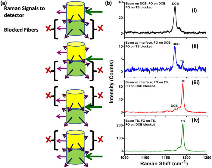
As a demonstration of our technique, we first show the results observed for two different powder layers packed in a glass vial. In principle, there is a finite probability of diffusely scattered light from the sample coming out of the vial in all directions, and, therefore, one can choose to use different collection geometries around the vial. In the case of solid powders, however, the light scattering intensity depends on the particle size and distribution, the distance from the point of photon entry and also on the density of packing21,22. In the following experiments, two different chemicals were packed one on top of the other in a glass vial (Figure 2a). The Raman signals were collected from all sides of the sample using optical fibers as shown in figure 2a and the Raman excitation laser beam was directed towards the container surface. At first, the incident excitation beam was directed at various locations, i.e., at the interface, at the top layer and at the bottom layer, while partially blocking collection fibers at different layers. For example, in Figure 2 (i), the excitation laser was directed towards the top layer and five collection fibers were placed around the top layer while blocking the fibers around the bottom layer. The observed Raman signals of, 1, 4 –dicyanobenzene (DCB) (top layer) and t-stilbene (TS) (bottom layer), using UMARS are presented in Figure 2b. It was observed that the Raman signals of the top layer could be obtained predominantly with negligible contribution from the bottom layer. Similarly, when the excitation beam was incident at the interface of the bilayer and the Raman signals were collected using the collection fibers located around the top layer i.e. DCB (while blocking the collection fibers around the bottom layer (TS)), predominantly the top layer Raman signal could be obtained (Figure 2b (ii)). Alternatively, we interchanged the observation regions by blocking the fibers to the top layer and observing only the fibers from the bottom layer. The dominant Raman signal from the bottom layer of the sample was obtained in this arrangement (Figure 2b (iii)). Further, when the excitation was shifted to the bottom layer and the collection fibers were placed around the bottom layer, only the spectrum of the bottom layer of the sample was observed (figure 2b (iv)). This demonstration clearly indicates that with multiple angle collection, layer specific information can be obtained using UMARS.
Figure 2.
(a) Schematic of the experimental set-up for bilayer powders, and (b) Resulting UMARS spectra demonstrating depth sensitive detection of bilayer solid powders 1, 4-Dicyanobenzene (DCB) (TOP) and t-Stilbene (TS) (BOTTOM) packed in glass vial using excitaion at various incident beam locations and by blocking collection fibers at different layers. (i) Beam incident on the top layer DCB, collection only from the top layer, (ii) Beam incident at the interface of the bilayer, collection only from the top layer, (iii) Beam incident at the interface of the bilayer, collection only from the bottom layer TS, and iv) Beam incident on the bottom layer, collection only from the bottom layer TS. Spectral acquisition time 100 s.
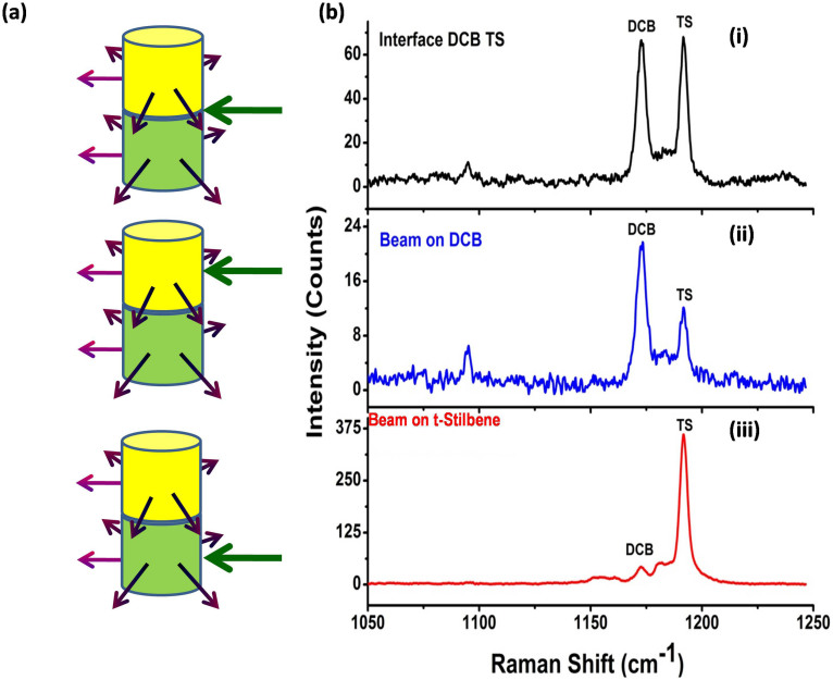
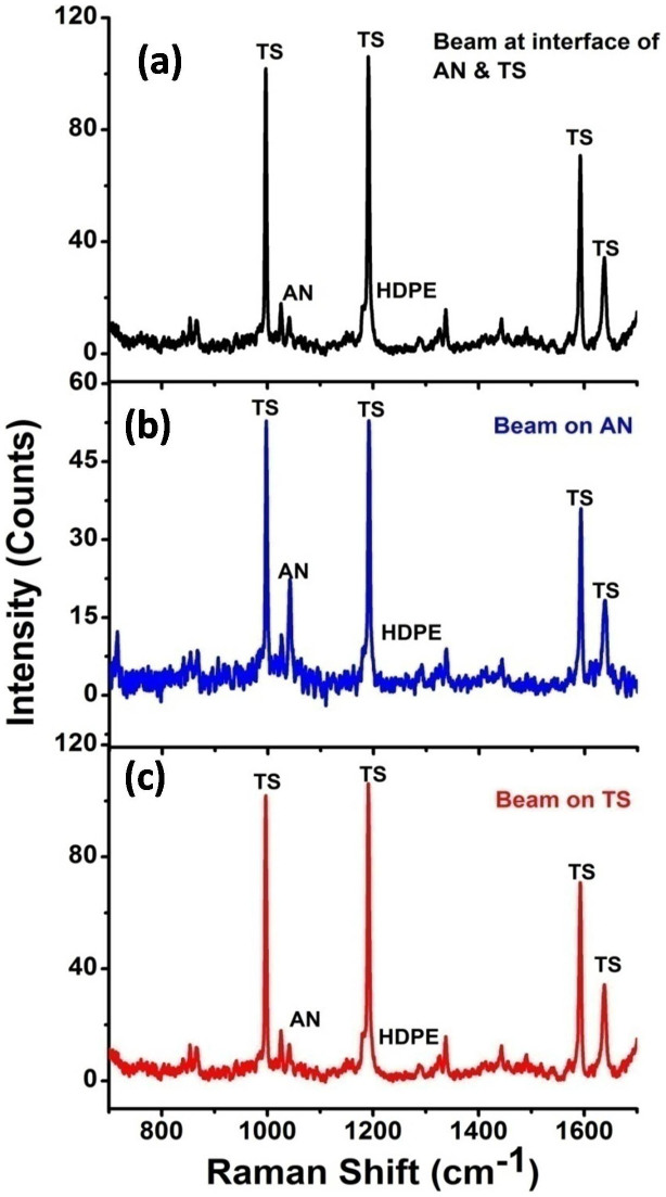
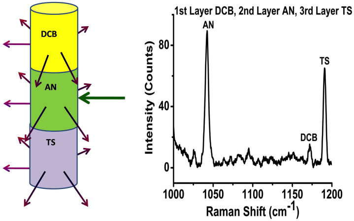
In the next set of experiments no fibers were blocked and Raman photons were collected using all the ten fibers at different heights. 1, 4-dicyanobenzene and t-stilbene bilayers of thickness 1 cm each were packed inside glass vials. UMARS experiments were carried out by 1) laser beam excitation at the interface, 2) laser beam excitation at the top-layer i.e. at 1, 4-dicyanobenzene and 3) laser beam excitation at the bottom layer i.e. at t-stilbene (Figure 3). It is apparent from the observed Raman spectra that, by suitably choosing the excitation region and the collection location, one should be able to discriminate the samples in different layers. Since layer-specific Raman signatures could be obtained using UMARS, the next obvious step was to ascertain whether this technique could be applied in real situations such as the detection of concealed explosives such as ammonium nitrate (AN) packed in a high density poly ethylene (HDPE) container. Therefore, similar experiments were also conducted using a commercial HDPE container (inner diameter 25 mm and wall thickness 1 mm) instead of glass vials, filled with bilayers of ammonium nitrate and t-stilbene (Figure 4). In this case, too, we obtained the Raman spectra of both powders with minimal interference from the container spectrum reflecting the relative path lengths through inner layers and HDPE. We distinguished the Raman signals from the concealed ammonium nitrate (AN) along with a barely visible HDPE peak at 1294 cm−1 (Figure 4). The explosive AN, in spite of its low Raman cross section, could readily be detected when irradiated at AN or at the interface. As a final demonstration of UMARS, experiments on tri-layers of DCB, AN and TS were undertaken in the glass vial (Figure 5). All the three compounds could be clearly distinguished in this case, too. Thus, our technique readily yielded content specific signals by suitably avoiding the contribution from the container signal, thereby reducing the signal processing time.
Figure 3.
(a) Schematic of the bilayer experiment, and (b) Resulting UMARS spectra showing detection of bilayer solid powders 1, 4-Dicyanobenzene (DCB) (TOP) and t-Stilbene (TS) (BOTTOM) packed in glass vial using UMARS at various incident beam locations. (i) At the interface of the layers, (ii) Beam incident on DCB, and (iii) Beam incident on TS. Spectral acquisition time 100 s.
Figure 4. Detection of bilayer solid powders Ammonium nitrate (AN) and t-Stilbene (TS) packed in commercial HDPE container using UMARS at various incident beam locations.
(a) At the interface of the layers, (b) Beam incident on AN, and (c) Beam incident on TS. Note that the signal from the container wall is insignificant. Spectral acquisition time 200 s.
Figure 5. Detection of trilayer solid powders; 1st layer 1, 4- Dicyanobenzene (DCB), 2nd layer Ammonium nitrate (AN) and the 3rd layer t-Stilbene (TS) packed in glass vial container using UMARS.
Spectrum recorded with the excitation beam at AN. Spectral acquisition time 500 s.
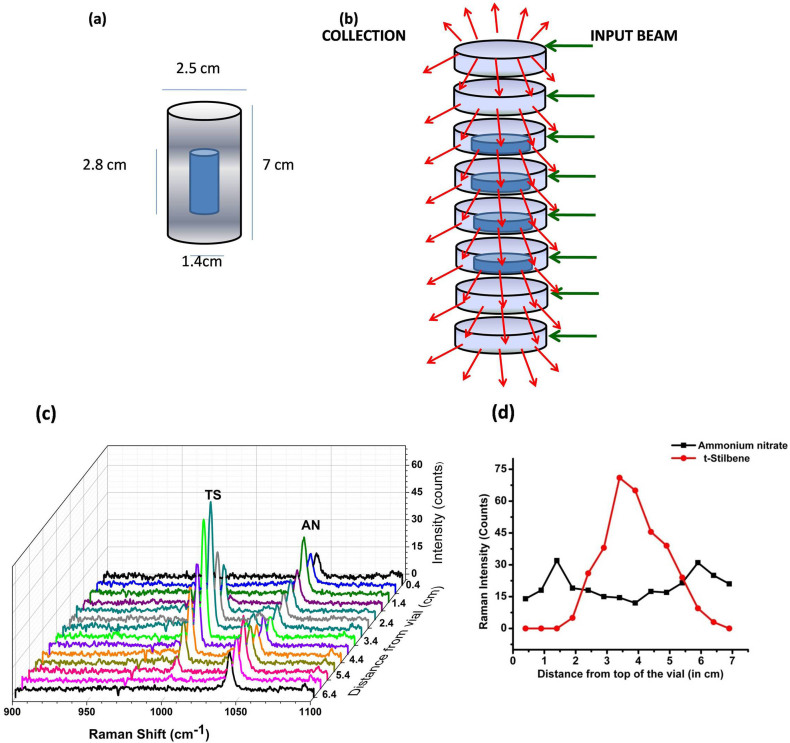
Thus far, we have considered two or three layers of powders, one on top of the other for UMARS investigation. Having obtained layer-specific information, we explored another sample configuration (Figure 6 (a)) where one sample is completely concealed/buried or surrounded by another layer of a different chemical species, which is a more likely scenario in the medical diagnostic arena (for example bone surrounded by tissue), and in the detection of explosives concealed in a non-metallic container. Figure 6 (a) schematically depicts such a setup where a cylindrical glass container (outer) with a diameter of 2.5 cm and a height of 7 cm was filled with ammonium nitrate that constituted the outer layer. t-Stilbene powder packed in the form of a oblong ampoule (inner container) of diameter 1.4 cm and height 2.8 cm was placed in the middle of the ammonium nitrate layer. The excitation fiber was located on one side and the ten collection fibers were equally spaced around the vial over 360° and care was taken to maintain the collection plane the same as the illumination, as seen in figure 6 (b). The UMARS experiment was first performed at the top end of the whole container. The whole container was then vertically translated by 0.5 cm steps and a Raman spectrum was recorded at each step. (This way the excitation and collection fibers remained in the same plane throughout the experiment). In other words, slices of Raman signals from the sections over the entire length of the cylindrical vial were obtained to discriminate and identify the layered materials. Figure 6 (c) shows the three-dimensional Raman spectra of the sample with respect to the distance from the top (0.4 cm) to the bottom (6.4 cm) of the container. It is interesting that as we approach the middle of the container, the signals from the material buried/concealed inside (TS) become more intense. This is also apparent from the plot (Figure 6 (d)) of the variation of the Raman intensities of the 1044 cm−1 peak of AN and the 997 cm−1 peak of TS with respect to height. It was observed that the Raman signals for AN could be obtained at 0.4 cm from the top of the vial, whereas at this position the TS Raman peak was completely absent. As we progressed along the height of the vial, the TS Raman signal started to appear and peaked at ~3.4 cm from the top. At the same time, AN signals decreased somewhat but remained clearly visible. The trend unequivocally demonstrates that AN constitutes the outer layer while TS was present around the middle of the vial. The AN signals response in Figure 6d, can be explained by the fact that at the heights where the inner container is located/concealed, the total amount of the AN is considerably less, which, in turn, corresponds to low Raman intensity.
Figure 6. UMARS of hidden object; (a) 1st layer Ammonium Nitrate (AN), 2nd layer t-Stilbene (TS) concealed inside AN, (b) Schematic representation of illumination and collection of Raman spectra from different slices of the cylindrical glass vial, (c) Raman signal of the bilayer sample at different heights, and (d) Raman intensity variation of AN & TS as a function of height.
Vertical step size 5 mm. Spectral acquisition time 500 s.
Discussion
The photons incident on the container wall interact with the sample depending on the number of scattering events on their pathway, i.e., depending on the scattering properties of the container and the sample: the concentration/density, particle sizes, refractive indices and absorption properties. The scattering properties of the sample can be characterized by a single parameter l* corresponding to the transport length of the light in the medium, also defined as the photon path after which the photon direction is totally randomised23. The penetration depth of the light is therefore proportional to l*. The Raman signal detected from the samples inside the container is the sum average of the number of photons coming from all depths; the photons detected by the detector can come from any depth. In the backscattering collection method, the particles close to the surface contribute more to the Raman signal than the particles located deeper in the sample. A simple consideration of the statistics of the photon trajectories indicates that the signal is inversely proportional to the square of the depth considered, for a depth greater than the transport length l*: scatterers contained in a layer twice deeper than another, result in four times lower contributions to the signal24,25. (We would like to note that it might be of interest to understand the relative material and angle specific Raman intensities accurately, however, it is well known that predicting absolute Raman intensities is not an easy task even for a given collection geometry26,27). In backscattering collection geometry this leads to a dominant contribution from the container wall to the signal. One way of eliminating or discriminating the surface signal from the rest is to introduce an offset between the excitation and collection regions11. The main drawbacks of such an approach and also the transmission Raman spectroscopy are that (a) they are collection geometry-specific and distance dependent (normally <12 mm) and (b) the pure spectrum of materials below the surface can only be observed by the subtraction of the surface signals. It is important to note that this collection geometry restriction for the detection of materials hidden inside the containers can very well be avoided by choosing other collection geometries, as presented here, using UMARS. We are currently modeling the photon migration paths using Monte-Carlo simulations, which indeed confirm the emission of Raman photons in all directions (manuscript in preparation). Since the multiple scattered light from within a sample can come out in all directions and at all angles, the technique can be applied in various experimental geometries. Thus, as we have experimentally demonstrated, layer-specific Raman signatures of layered samples concealed in glass vials and commercial HDPE containers could be obtained using UMARS. It was also possible not only to discriminate but also identify materials concealed underneath another overlaying sample. Using UMARS on different sections or slices of a layered substance one can reveal the position of the layers along with its molecular identification. The technique is simple and straightforward in its design and has the potential to be used not only for detecting hazardous chemicals buried in different types of nonmetallic containers, but also for obtaining the signatures and imaging of tissues and other turbid media of biological importance including bones, teeth, tumors, blood etc. We anticipate that, with suitable modifications, the technique can also be applied for frequency-specific 3D imaging of turbid media.
Methods
UMARS Experiment
The Raman experiment was carried out using the 830-nm output of a cw laser diode (Sacher Lasertechnik), typically operated at 900 mA. The optical fibers used in the UMARS experiment (Fiber Tech Optica, Canada), consisted of low OH, all silica, step-index, multi-mode fibers with a total length of 3.5 m, having collection efficiency 0.22. The input light was delivered using one delivery fiber of 400 μm core diameter fitted at normal incidence close to the container wall. The Raman signals were collected from the samples using a set of upto ten optical fibers of the same core diameter, which were placed around the sample at approximately equal angles with respect to the input fiber. For instance, where five collection fibers were placed around the periphery of the sample, each optical fiber was located at ~60° from each other (including the input fiber). The collection fiber bundles terminated at the other end in a linear array attached to a telescopic arrangement fixed to the entrance slit of the spectrometer. The spectrometer (Horiba JobinYvon, f/4.1) was equipped with a LN2-cooled CCD camera (Symphony, 1024 × 256 pixels, pixel size 26 × 26 μm); a notch filter (Iridian, Canada) was used in front of the entrance slit to eliminate Rayleigh scattered light. The power was kept at about 100 −140 mW for all experiments described in this work. The acquisition time for the experiments was kept in the range of 100–500 s. All chemicals used were obtained from Sigma-Aldrich and used as received. The samples were solid powders filled in glass vials or commercial high-density polyethylene (HDPE) containers.
Author Contributions
S.S. designed and carried out the UMARS experiments, analyzed the data and wrote the manuscript; S.U. conceptualised and supervised the research programme, coordinated the work and contributed to the data analyses and text. All authors read and approved the manuscript.
Acknowledgments
The authors gratefully acknowledge Department of Biotechnology, Department of Science & Technology (DST), Council of Scientific & Industrial Research, Indian Institute of Science, Bangalore for their financial support. SU acknowledges the J.C. Bose fellowship from DST.
References
- Ahmad A. et al. Real-time in vivo computed optical interferometric tomography. Nature Photon 7, 444–448 (2013). [DOI] [PMC free article] [PubMed] [Google Scholar]
- Haisch C. Optical Tomography. Annu. Rev. Anal. Chem. 5, 57–77 (2012). [DOI] [PubMed] [Google Scholar]
- Zhang Q. S. et al. In vivo Optical coherence tomography of light-driven melanosome translocation in retinal pigment epithelium. Sci. Rep. 3, 2644 (1–8) (2013). [DOI] [PMC free article] [PubMed] [Google Scholar]
- Zeff B. W., White B. R., Dehghani H., Schlaggar B. L. & Culver J. P. Retinotopic mapping of adult human visual cortex with high-density diffuse optical tomography. PNAS 104, 12169–12174 (2007). [DOI] [PMC free article] [PubMed] [Google Scholar]
- Alivisatos P. The use of nanocrystals in biological detection. Nat. Biotechnol. 22, 47–52 (2004). [DOI] [PubMed] [Google Scholar]
- Ntziachristos V., Tung C. H., Bremer C. & Weissleder R. Fluorescence molecular tomography resolves protease activity in vivo. Nature Med. 8, 757–760 (2002). [DOI] [PubMed] [Google Scholar]
- Evans A. C., Marrett S., Torrescorzo J., Ku S. & Collins L. MRI-PET correlation in three dimensions using a volume-of-interest (VOI) atlas. J. Cereb. Blood Flow Metab. 11, A69–A78 (1991). [DOI] [PubMed] [Google Scholar]
- Schneider G. et al. Three-dimensional cellular ultrastructure resolved by X-ray microscopy. Nat. Meth. 7, 985–987 (2010). [DOI] [PMC free article] [PubMed] [Google Scholar]
- Wang L. V. Multiscale photoacoustic microscopy and computed tomography. Nature Photon 3, 503–509 (2009). [DOI] [PMC free article] [PubMed] [Google Scholar]
- McCreery R. L., Fleischmann M. & Hendra P. Fiber optic probe for remote Raman spectrometry. Anal. Chem. 55, 146–148 (1983). [Google Scholar]
- Matousek P. et al. Subsurface probing in diffusely scattering media using spatially offset Raman spectroscopy. Appl. Spectrosc. 59, 393–400 (2005). [DOI] [PubMed] [Google Scholar]
- Schulmerich M. V. et al. Non- invasive Raman tomographic imaging of canine bone tissue. J. Biomed. Opt. 13, 020506-020506-3 (2008). [DOI] [PMC free article] [PubMed] [Google Scholar]
- Schrader B., Hoffmann A. & Keller S. Near-infrared Fourier transform Raman spectroscopy: Facing absorption and background. Spectrochim. Acta A 47, 1135–1148 (1991). [Google Scholar]
- Matousek P., Draper E. R. C., Goodship A. E., Clark I. A., Ronayne K. L. & Parker A. W. Noninvasive Raman spectroscopy of human tissue in vivo. Appl. Spectrosc. 60, 758–763 (2006). [DOI] [PubMed] [Google Scholar]
- Pine D. J., Weitz D. A., Chaikin P. M. & Herbolzheimer E. Diffusing wave spectroscopy. Phys. Rev. Lett. 60, 1134–1137 (1998). [DOI] [PubMed] [Google Scholar]
- Park J. H. et al. Subwavelength light focusing using random nanoparticles. Nat. Photonics 7, 454–458 (2013). [Google Scholar]
- Maret G. Diffusing wave spectroscopy. Curr. Opin. Coll. Inter. Sc. 2, 251–257 (1997). [Google Scholar]
- Bohren C. F. & Huffman D. R. Absorption and Scattering of Light by Small Particles (John Willey & Sons Inc. USA, 1983). [Google Scholar]
- Sasic S. & Ozaki Y. Raman, Infrared, and near-IR chemical Imaging (John Wiley & Sons Inc. USA, 2010). [Google Scholar]
- Strangman G., Boas D. A. & Sutton J. P. Noninvasive neuroimaging using near infrared light. Biol. Psychiatry 52, 679–693 (2002). [DOI] [PubMed] [Google Scholar]
- Yguerabide J. & Yguerabide E. E. Light-Scattering submicroscopic particles as highly fluorescent analogs and their use as tracer labels in clinical and biological applications: Experimental Characterization. Anal. Biochem. 84, 157–176 (1998). [DOI] [PubMed] [Google Scholar]
- Schweinsberg D. P. & West Y. D. Quantitative FT Raman analysis of two component systems. Spectrochimi. Acta A 53, 25–34 (1997). [Google Scholar]
- Chen Z. P. et al. Quantitative analysis of powder mixtures by Raman spectroscopy: the influence of particle size and its correction. Anal. Chem. 84, 4088–4094 (2012). [DOI] [PubMed] [Google Scholar]
- Weitz D. A. & Pine D. J. Dynamic Light Scattering, the method and some applications [Brown, W. (ed.)] [P. 179] (Clarendon, Oxford, 1993). [Google Scholar]
- Brun A., Dihang H. & Brunel L. Film formation of coating studied by diffusing-wave spectroscopy. Progress in Organic Coatings 61, 181–191 (2008). [Google Scholar]
- Biswas N. & Umapathy S. Partitioning the total reorganization energy into its vibrational and solvent contributions using resonance Raman intensities. Chem. Phys. Letts. 294, 181–190 (1998). [Google Scholar]
- Biswas N. & Umapathy S. Simple approach to determining absolute Raman cross sections using an optical parametric oscillator. Appl. Spectrosc. 56, 496–499 (1998). [Google Scholar]


