Abstract
We report on a pilot study of dynamic lung electrical impedance tomography (EIT) at the University of Manchester. Low-noise EIT data at 100 frames per second (fps) were obtained from healthy male subjects during controlled breathing, followed by magnetic resonance imaging (MRI) subsequently used for spatial validation of the EIT reconstruction. The torso surface in the MR image and electrode positions obtained using MRI fiducial markers informed the construction of a 3D finite element model extruded along the caudal-distal axis of the subject. Small changes in the boundary that occur during respiration were accounted for by incorporating the sensitivity with respect to boundary shape into a robust temporal difference reconstruction algorithm. EIT and MRI images were co-registered using the open source medical imaging software, 3D Slicer. A quantitative comparison of quality of different EIT reconstructions was achieved through calculation of the mutual information with a lung-segmented MR image. EIT reconstructions using a linear shape correction algorithm reduced boundary image artefacts, yielding better contrast of the lungs, and had 10% greater mutual information compared with a standard linear EIT reconstruction.
Keywords: 3D lung EIT, MRI, mutual information, image co-registration
1. Introduction
Electrical impedance tomography is a non-invasive technique that aims to reconstruct the internal conductivity distribution of a given subject from electrical measurements obtained on the periphery. Since the development of the technique in the early 1980s by Barber and Brown (1984), there has been widespread interest in the clinical application of thoracic EIT. Several review articles by Muders et al (2010), Bodenstein et al (2009), Costa et al (2009a), Adler et al (2012), Lundin and Stenqvist (2012) and Frerichs (2000) provide the reader with the current status of clinical activity and also detail the broad spectrum of specific thoracic EIT application areas. Applications include the assessment of pulmonary ventilation (Frerichs (2000) and Zhao et al (2010)), lung perfusion (Frerichs et al (2009)), pulmonary oedema (Kunst et al (1999)), emphysema (Smit et al (2003)) and lung injury (Hinz et al (2007)). These studies demonstrate that thoracic EIT promises to become a routine bedside monitoring tool for critically ill patients who undergo mechanical ventilation, and is already beginning to play an important role in optimizing ventilator settings for such patients.
The majority of EIT image reconstruction systems, however, still do not exhibit a consistent level of performance across different patients, or for the same patient at different data acquisition times. This is clearly an essential ingredient for the technique to gain credibility across the medical community as a bedside monitoring tool. A major contributing factor behind poor reproducibility is a result of inadequate modelling approximations that are used in the reconstruction algorithm. Additionally, virtually all EIT systems still deploy a single ring of 16 electrodes placed on a transverse plane around the thorax and perform reconstructions onto a 2D transverse slice, and operate at a modest 40 fps (a single frame corresponds to collection of all measurements for a specific protocol.) Physically, current can not be constrained to lie in the 2D plane, and mathematically the potential from a point current source has different decay rates in 2D and 3D (Lionheart (1999)). Inaccurately known boundary shape and electrode positions are also known to result in major artefacts in image reconstruction (Adler et al (2006), Zhang and Patterson (2005), Lionheart (1998)). Many EIT systems assume the boundary shape is circular, elliptical, or at best a generic thorax shape, which can be a rather crude approximation to a genuine thorax cross section. The difficulty of obtaining a sufficiently accurate approximation to the shape is amplified for temporal reconstructions. During respiration the expansion and contraction of the rib cage causes the displacement of thoracic tissues, the external shape and the attached electrodes. This movement creates EIT measurements which appear spurious, with the measured voltage signals often being dominated by movement effects and not the underlying tissue conductivity changes. This effect can result in large boundary artefacts in reconstructed images if such measurement data are used on a static geometrical model which can render the overall reconstruction meaningless.
A crucial step towards EIT reproducibility is to perform a quantitative assessment of the spatial resolution obtainable for different EIT reconstruction algorithms and to compare EIT with complementary imaging modalities. The spatial resolution of EIT has been assessed in several experimental and clinical studies involving spontaneous and artificial ventilation against well established imaging techniques e.g. X-ray computed tomography (CT), positron emission tomography and single photon emission CT (Victorino et al (2004), Costa et al (2009b), Kunst et al (1998), Richard et al (2009), Hinz et al (2003) and Frerichs et al (2002)). However, none of these studies have made direct comparisons, or quantitative assessments, of the spatial accuracy of EIT with a second high resolution modality using image co-registration and mutual information as we will present here.
The aim of this paper is to systematically address the problems associated with image reproducibility outlined above, by describing a methodology for 3D thoracic EIT reconstruction. We report on a study at the University of Manchester involving 2 healthy subjects who had MR scans in the supine position, in addition to EIT data acquired with the Manchester fEITER system (McCann et al (2011)) in the supine and seated positions. Potential reconstruction artefacts associated with inaccurate model dimension, boundary shape and electrode positions are addressed by using an MR image of the subject to inform the external shape of a 3D EIT reconstruction model of the thorax. Similarly, MRI fiducial markers placed at the electrode positions aided electrode positioning within the model. Small changes in the boundary and electrode positions during the breathing cycle are addressed by calculating the sensitivity of the EIT forward model with respect to the boundary shape, and incorporating this into a robust 3D temporal difference image reconstruction algorithm. Qualitative comparisons are made between the spatial resolution obtained using both the standard and boundary movement difference reconstruction algorithms on the MRI-informed reconstruction model, via co-registration with the original MR image. We also implement a simple and novel performance criterion which enables a quantitative measure of EIT reconstruction quality by calculating the mutual information of the EIT images with a lung-segmented MR image of the subject, as discussed in section 2.4.
2. Methods
2.1. EIT and MRI data acquisition
An array of 32 electrodes was arranged on the subject as two transverse planes of 16 electrodes equidistantly spaced around the chest at approximately the fourth and sixth intercostal spaces, along with an abdominal reference electrode, as illustrated in figure 1. EIT measurements were acquired using the EIT sub-system of the biomedical fEITER instrument (McCann et al (2011)), which offers not only a high signal-to-noise ratio (SNR) approaching 80 dB on bench-top phantoms, but has also been designed to meet the IEC 60601-1 patient safety requirements. In this study, a nearest-neighbour current injection protocol was used with a total of 20 current patterns which included 8 independent horizontal injections per transverse electrode plane. Sinusoidal current injections of 0.5 mA amplitude at 10 kHz frequency were input and the EIT instrument recorded nearest-neighbour voltage pairs at 100 fps. EIT data were recorded whilst the subject carried out basic breathing procedures in 1 minute blocks. Breathing procedures involved normal and progressively deeper tidal breathing regimes interspaced with reference conditions of typically 5 second breath-holds at both inspiration and expiration. MRI fiducial markers were substituted for the EIT electrodes at all electrode locations immediately after the last EIT data collection, before carrying out an MRI scan using a T2-weighted half-Fourier acquired single-shot turbo spin-echo (HASTE) protocol on a 1.5 T Philips Achieva scanner (Philips Healthcare, Best, the Netherlands) under the same breathing procedures as used during the EIT tests. The MR scans consisted of 1 cm thick contiguous axial slices, which were cardiac gated and tuned for the conditions of normal breath-holding, at maximum inspiration and expiration. The whole procedure was approved by the local ethics committee and the subjects gave written, informed consent.
Figure 1.
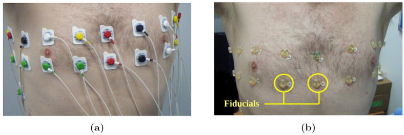
Electrode arrays; (a) electrodes attached during EIT data acquisition and (b) MRI fiducial markers to inform electrode positions.
2.2. Finite element modelling of the human torso
The external boundary shape of the subject was obtained from a transverse MR image slice at the fifth intercostal spacing at a breath-hold at maximum inspiration. The contour of the external shape was defined by 50 equispaced points and the contour of each lung by approximately 25 equispaced points. A 3D finite element (FE) forward model extruded along the caudal-distal axis was then generated using EIDORS 3.6 (Adler and Lionheart (2006)§) calling the Netgen mesh generator (Schöberl (1997)). Ider et al (1990) have previously performed a mathematical analysis of extruded models with a single transverse plane of electrodes. The present methodology is an extension of their approach because multiple planes of electrodes can be incorporated into the model. The method of extrusion has been applied to swine data as described by Grychtol et al (2011). The FE forward model consisted of 32 electrodes with typically 20000 tetrahedral elements and 5000 vertices, modelled to a depth of 10 cm. The transverse MR image slice and surface mesh of a typical forward model is shown in figure 2. All electrodes were modelled to a diameter of 1 cm, which is consistent with those applied to the subject. A high mesh density was chosen in the vicinity of each electrode where the electric field is largest. The lungs segmented from the MR image were also included in the forward model and used as prior information in the forward problem. A 3D FE model was generated with the same boundary shape as the forward model, but with no electrodes and a lower mesh density, for the reconstruction problem. A reconstruction model typically consisted of 10000 tetrahedral elements and 2500 vertices. From the forward and reconstruction models a mapping matrix was generated to transform between the coarse and fine discretisations, as described by Adler et al (2008), allowing one to solve the forward problem sufficiently accurately on the fine model as well as representing the reconstructed conductivity on the coarse model.
Figure 2.
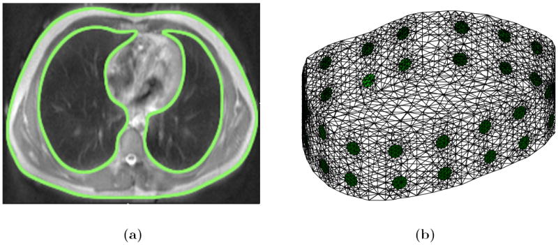
FE model generation; (a) segmented MR slice with thorax and lung shapes highlighted and (b) extruded ‘2.5D’ FE model generated in EIDORS.
2.3. Image reconstruction with shape corrections
As previously discussed, a major source of artefacts in thoracic EIT reconstructions is due to an inaccurately known boundary shape. Given full knowledge of the Neumann-to-Dirichlet (NtD) on the true domain, with conductivity assumed a-priori to be isotropic, it was shown by Lionheart (1998) that the data measured on the true domain will only be consistent with an isotropic conductivity in the model domain if the true domain and model domain are related by a conformal map. Reconstruction algorithms have been proposed that rely on the conformal structure of a deformed conductivity. It has been shown by Kolehmainen et al (2013), that the shape and conductivity in 2D can be determined using techniques from quasi-conformal maps and minimally anisotropic conductivities. Lastly, it has been shown by Kolehmainen et al (2007) that the shape and conductivity of an isotropic conductivity in 3D can be determined up to a rigid motion. Specifically, when the metric corresponding to an isotropic conductivity is pushed forward by a domain distortion it is conformally flat and this is equivalent to the vanishing of the Cotton-York tensor. A reconstruction algorithm including a penalty term on this tensor has been proposed.
Alternative reconstruction algorithms to estimate the shape and conductivity from knowledge of the NtD map have recently been proposed in the literature. Firstly, a Bayesian approximation error approach has been proposed by Nissinen et al (2011) to reconstruct the conductivity and a low rank estimate of the shape. This approach treats all sources of modelling error such as the FE discretisation and the boundary shape, but not the unknown conductivity, as ‘nuisance’ parameters. The modelling error covariance is estimated from an ensemble of 150 CT images of thorax shapes and this covariance is then incorporated into a standard regularised Gauss Newton method to reconstruct the conductivity. Secondly it has been shown by Dardé et al (2013) that the forward operator F(h), now operating on a C1 perturbation of the boundary given by a function h, with σ fixed, is also Fréchet differentiable at the origin. That is, given h ∈ C1(∂Ω, ℝ3), and let Dh(x) = x + h(x), x ∈ ∂Ω, represent a perturbation of the boundary, then and an explicit form for the derivative operator, , is calculated. The weak formulation for the derivative falls just short of the conventional H1 Sobolev space desired for a FE method, but a dual formulation is derived and a sampling method proposed to estimate the derivative and an iterative algorithm outlined to estimate the shape and conductivity distribution.
The approach outlined here is to calculate the Gâteaux derivative of the forward problem with respect to the boundary shape at the electrodes, leaving the rest of the boundary fixed. This method could equally be applied to other boundary locations, but since the largest sensitivity of measured data to shape changes will be at the electrodes, we only calculate this at the electrode positions. In effect we are assuming the shape has been sufficiently well approximated from the MR image and are only accounting for small corrections from electrode movement due to breathing. We denote the domain Ω ⊂ ℝ3 with boundary ∂Ω, and the isotropic, real and positive conductivity σ : Ω → ℝ+. The boundary has L well separated electrodes, El ⊂ ∂Ω, l = 1 : L, attached with centre of mass positions υl ∈ ℝ3. We consider a prescribed electrode current vector, , with Σl IL = 0, with the resulting electrode potential vector, , and internal potential u (defined up to a constant). Let , denote the vector of contact impedances present at the electrode-domain interfaces. A finite difference method on the FEM formulation of the forward problem is used, and an approximate derivative with respect to electrode movement, Jm : ℝ3L → ℝm, is calculated, which can be considered as the firrst partial derivative of the forward problem with respect to each coordinate of each electrode (Soleimani et al (2006) and Crabb et al (2012)). To calculate this derivative we need some modelling assumptions on the behaviour of electrode movement. Firstly, the shape of the electrode can conceivably deform as it moves along the boundary if flexible ‘elastic’ electrodes were used. We use an identical perturbation for each node of a given electrode and so we are assuming the electrodes move along the boundary rigidly without changing shape. Secondly, to calculate the normal component of electrode movement in the finite difference approximation, a small piece of conductivity has to be added under each electrode. We assume the conductivity is constant in a neighbourhood of the electrode, and so the conductivity of the small additional piece of tissue added is the same as under the unperturbed electrode. The GREIT reconstruction algorithm (Adler et al (2009)), engineered for 2D linear reconstructions, includes a variation on the algorithm discussed in this section to compensate for electrode movement. The array of 32 electrodes, and flexible current injection capability of the fEITER system, allow us to explore the effectiveness of 2.5D reconstructions.
Denote the forward operator Fσ,υ : ℝL → ℝL/ℝ, mapping a given current pattern applied to the electrodes to the measured voltages on the electrodes. The vector of measured voltages over all current patterns can then be written as V = ZI Fσ,υI, where Z ∈ ℝm×L is a linear measurement operator mapping the boundary voltages over all current patterns, I ∈ ℝL, to the specific measurement protocol. The forward problem is modelled through the complete electrode model (CEM), considered the most physically accurate forward model for EIT (Somersalo et al (1992)). We discretise the domain into N elements and V nodes and choose a piecewise constant and piecewise linear basis to represent the conductivity and interior potential respectively. The conventional EIT reconstruction problem is to determine σ stably from knowledge of V. It is well known that the forward problem in EIT is Fréchet differentiable with respect to L∞ conductivity perturbations (Kaipio et al (2000)). If there are a total of m measurements over all input current stimulations, and using a piecewise constant representation of the conductivity, the Fréchet derivative simplifies to a Jacobian matrix Jc : ℝN → ℝm, readily calculated via a piecewise linear FEM (see Polydorides (2002) for details.) The forward problem can now be linearised through a Taylor series expansion as
| (1) |
where ∥(σ, υ)∥ := ∥σ∥∞ + ∥υ∥∞. The estimation of conductivity and electrode positions x := (σ, υ) from the data is approached from a probabilistic viewpoint. The voltages are assumed to be related by V = ZI F (σ, υ) I + n, where n ∈ ℝm represents the measurement channel noise. We assume mean zero Gaussian noise with covariance matrix Γe ∈ ℝm×m and a Gaussian smoothness prior on the conductivity and electrode positions, with covariance matrix Γσ, υ ∈ ℝ3L+N×3L+N and mean xr := (σr, υr). The measurement noise is also assumed to be independent and identically distributed (i.i.d) and the conductivity and electrode position changes are assumed to be independent from one another and separately i.i.d. These assumptions imply that and is a diagonal matrix with entries if i ≤ N and if N < i ≤ N + 3L. Physically α and β can be interpreted as the ratios of expected changes of conductivity and electrode position to the measurement noise standard deviation.
The maximum a-posteriori (MAP) estimate of xi, at the ith temporal data frame, Vi, is equivalent to
| (2) |
The minimiser of the functional is approached via a linearised Gauss-Newton method to compute an update at the ith measured temporal data frame. The initial guess is chosen here as the prior distribution, xr, and we denote Vr = ZI F (xr) I and δVir = Vi − Vr. The gradient, gri ∈ ℝN +3L, of the functional (2), at the point xr and ith temporal data frame is
| (3) |
The Gauss-Newton method assumes all second order partial derivatives of forward problem FI with respect to σ and υ can be neglected. This, and the assumption that the prior covariance matrix is diagonal, allows us to write the Hessian matrix, Hr ∈ ℝN+3L×N+3L, of the functional (2) at the point xr, as a 2 × 2 block matrix of the form
| (4) |
The first update of the Gauss-Newton scheme is then
| (5) |
where τ(1) is a linesearch parameter. We are only interested in the linearised difference between two data frames Vi and Vj, and so just set τ(1) = 1. The linearised reconstruction, δxij, between two data frames Vi and Vj is then
| (6) |
This solution was computed in EIDORS via the following procedure. Firstly the extruded mesh was generated as described previously and a constant conductivity assigned to the model. Simulated boundary voltages were acquired from this model using the same measurement protocol as the experiment, and in order to get a consistent scaling between the simulated and measured voltages, Vs and Vm respectively, a best fit homogeneous reference conductivity, σr, was computed using a formula derived by Kaipio et al (2000). The prior information of the lungs was then included by assigning the conductivity in the lung regions as 0.3σr. Using this reference conductivity the movement Jacobian, Jm, was calculated in EIDORS 3.6∥ along with the standard conductivity Jacobian, Jc, using the default Jacobian function¶. Image reconstructions were performed using two linear difference imaging methods. Firstly, using the described shape derivative method and secondly, a standard EIDORS method using a one-step linearised Gauss-Newton technique with standard Tikhonov regularisation. In the following section we discuss how optimal regularisation parameters α and β have been chosen using a mutual information technique.
2.4. EIT-MR image co-registration and mutual information
In this section we describe the EIT and MR image co-registration process, and the method used to calculate the mutual information between the EIT and MR images. The image co-registration process and mutual information calculation provides both a qualitative and quantitative measure of EIT reconstruction performance. Although mutual information techniques have been used in previous multimodal imaging studies (see Pluim et al (2003) for a review) such techniques have yet to be applied in the area of lung imaging using EIT.
The Manchester Confeitir software (McCormick et al (2007)) was used to convert the reconstructed EIT data from the irregular tetrahedral mesh into a matrix with 2 mm-cubic isotropic voxels each representing a conductivity change and the coordinates of each voxel were then transformed so that they were in the same space as the MRI data. The software efficiently identifies the tetrahedron whose centroid is closest to the centre of any given voxel. Additionally, the application of a small threshold to the EIT data aided improved clarity of the subsequent visualisations. This typically involved discarding 5% of extreme points from the visualisation. The EIT images were transformed to the Nifti data format for subsequent importing into 3D Slicer (Pieper et al (2004)). The MRI data were imported into 3D Slicer separately and co-registered using methods validated with bench-top phantoms by Davidson et al (2012). This involved marking up a set of control points around the outside of the torso on both the EIT and MRI data using the fiducial registration module of 3D Slicer, followed by least squared minimisation of the distance between the two sets of data in space.
We denote two images A and B, each with N cubic voxels, and each voxel having a positive grayscale value. The probability distribution of A, pA(a), is defined as the number of voxels in image A that have pixel value a, normalised by N. The joint probability distribution of A and B, denoted pA,B(a, b), is then calculated as the number of times out of N that pixel in A contains a and the same pixel in B contains b normalised by N. The Shannon entropy, in the imaging context, is a measure of the information content of an image, measured in bits. The information content of a single event, that is a particular grayscale value of an image, is proportional to the log of the inverse of the probability of an event. The total information content of an image, or entropy, is the information content of a single event, weighted by the probability that the event occurs, summed over all events. The total entropy of A, and the joint entropy of A and B, are thus expressed as
| (7) |
respectively. The mutual information of A and B, IA,B, is defined as the total entropy of A and B minus the joint entropy, IA,B = HA + HB − HA,B, which equates to
| (8) |
It can be shown that 0 ≤ HA ≤ log(N), where HA = 0 when the image conveys no information i.e. it is featureless or homogeneous, and HA = log(N) for white noise. It is also true that 0 ≤ IA,B ≤ HA, where IA,B = 0 when A and B have no features in common and IA,B = HA = HB = HA,B when A and B are the same. Thus, the larger the mutual information between two images, the more similarities the two images share.
To calculate the mutual information, a threshold is first applied to the MR image to generate a binary image representing just lungs and chest, similar to the segmentation show in figure 2a. The intensity values of the cubic voxel based EIT image are then scaled linearly so they lie within the same range as the binary MR image. Both images have a finite number of voxels, and the probabilities in (7) are interpreted as histograms with 256 equispaced bins. If a bin is empty, 0 × log(0) is interpreted as 0. The MR and EIT images are both sampled at their voxel centres to estimate HA, HB and HA,B, and hence IA,B via (8). This calculation is therefore solely measuring how well a linearised EIT reconstruction is able to find the overall shape of the lungs. We perform the mutual information calculation over a range of regularisation parameters, (α,β), for both a standard (β = 0) and shape corrected reconstruction algorithm. This effectively results in a numerical parameter study to maximise the mutual information between MRI and EIT as a function of the parameters α and β.
3. Results and Discussion
3.1. Typical raw EIT measurements
Figure 3a shows typical voltage measurement data for two measurement sites, where i-j-k-l means current injection between electrodes i and j, and voltage measurement between electrodes k and l; site 13-14-15-16 refers to voltages at an anterior right hand side (RHS) location at the fourth intercostal space, whilst site 23-24-25-26 refers to a posterior left hand side (LHS) location at the sixth intercostal space. The effect of a brief breath-hold at approximately t = 20s can be clearly seen along with periodic changes consistent with the breathing rate of the subject. Additionally, the significant differences in the phase of the voltage changes for the two different sites suggests spatial differences of the underlying conductivity distribution within the lungs. Figure 3b illustrates raw measurement data from a fourth intercostal LHS posterior site (7-8-9-10) over a 10 s period with data points marked every 10 ms. The observations illustrate the excellent low noise characteristics (< 6 μV rms in recorded human lung data) of the raw human EIT data from the fEITER system at 100 fps. (Note that, despite its visual prominence, the approximate 1.5 μV rms quantisation noise level evident in figure 3b contributes less than 10% of the total noise power.)
Figure 3.
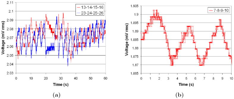
Voltage measurement sites for a seated subject; (a) two diametrically opposed sites with large breathing signal and (b) higher temporal resolution of large breathing signal.
3.2. Comparison of standard and shape correction algorithms
Figures 4 and 5 are typical of the 3D EIT image reconstructions acquired at 100 fps using the fEITER system. All images displayed in this paper are difference images relative to a maximum exhalation data frame, and blue and red indicate negative and positive conductivity changes respectively. Figures 4a and 4b illustrate difference images for a subject sitting upright at maximum (max) inhalation with the standard and shape correction reconstruction algorithms respectively. It can be clearly seen that the shape correction algorithm yields fewer boundary artefacts and sharper contrast between the lungs and background compared with the standard algorithm. These effects are also clearly visible in the 2D slices from the 3D image reconstructions for a second data set shown in figure 5. Figures 5a and 5b correspond to the standard method, α = 10−2, and the bottom figures 5c and 5d correspond to the perturbed method, (α, β) = (10−2, 4×10⁻²). Compensating for movement results in largely lateral changes in the electrode positions as well as a large reduction in boundary artefacts. This is promising as we do not expect any physiological mechanisms to produce large conductivities changes near the boundary.
Figure 4.
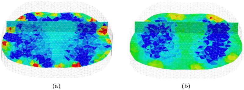
Reconstructions in 3D rendered in MayaVi software (Ramachandran (2001)); (a) and (b) are conductivity changes at max inhalation for a standard and shape corrected reconstruction respectively. The front of the chest is in the background, and transverse and coronal scalar-cut planes are shown within the 3D volume.
Figure 5.
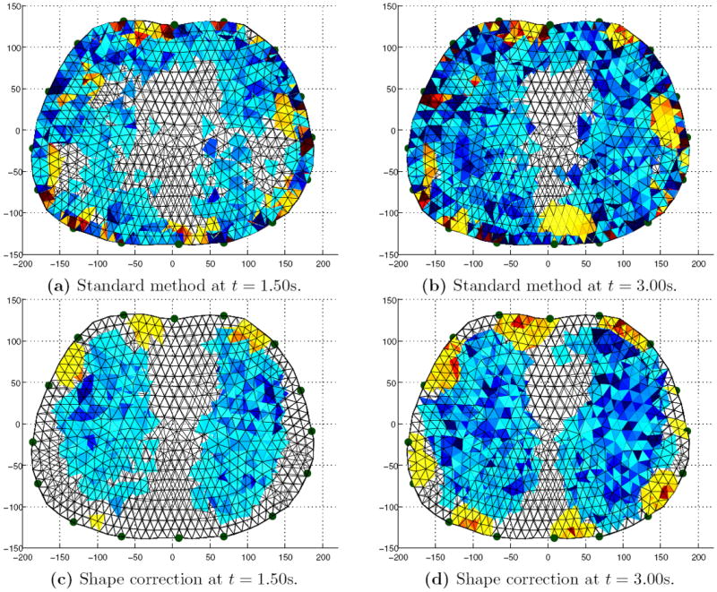
Image reconstructions viewed down the caudal-distal axis. Left and right: Mid inhalation (t = 1.50s) and max inhalation (t = 3.00s). Top and bottom: Standard algorithm and shape correction algorithm.
3.3. EIT-MR image co-registration and mutual information
Figure 6 shows an image co-registration example of MRI and EIT using 3D Slicer, for the subject in the sitting position at maximum inhalation. The left and right column are superior and inferior transverse planes respectively. The top row is the original MR image, the middle row the EIT reconstruction and the bottom row is the resultant image co-registration. From the images, it can be seen that the EIT reconstruction typically underestimates the physiological size of the actual cross-sectional areas of the lung. Inspection of the complete 3D data along the caudal-distal axis showed this to be true for the entire scanned lung volume.
Figure 6.
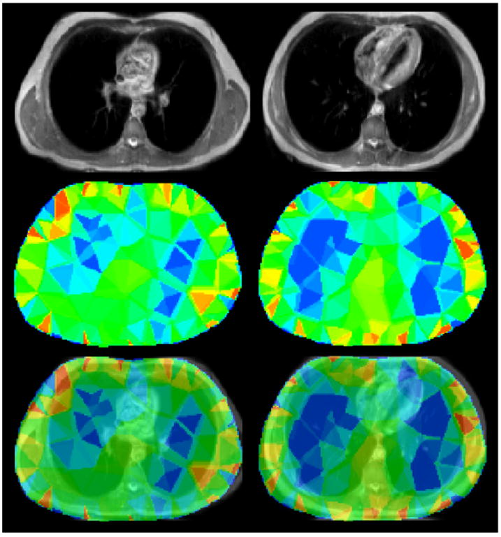
MRI and EIT image co-registration. Left to right columns: Superior and inferior transverse planes. Top to bottom rows: MRI image, EIT image and co-registered EIT and MRI images at the transverse slice.
Another observation to note is that the conductivity distribution exhibits a significant twisting effect in the superior transverse slice consistent with the 2D linear image reconstructions obtained by Bikker et al (2011) using the Dräger system. This is likely to be an artefact resulting from the inadequacies of the simple 2.5D extruded model used in the reconstruction. These inadequacies include the lack of inclusion of the heart in the model and possibly the model cut-off height along the caudal-distal axis being too small.
Figure 7 shows EIT and MRI co-registration examples for the subject in the seated and supine positions for the two reconstruction algorithms. The images clearly show that the shape correction algorithm decreases the boundary artefacts, and the EIT reconstructions again are typically found to underestimate the total lung volume. The shape correction algorithm also has an increased tolerance to positional changes of the subject in the supine position. Additionally, moving towards the superior position, the reconstructed lung regions tend to decrease in contrast to that of inferior slices, and we believe this could be due to the natural tapering of the lungs as we move in a superior direction. Three-dimensional ‘image fusion’ video clips created in 3D Slicer show that the shape correction algorithm provides a more physiologically meaningful reconstruction compared with the standard algorithm for all the data along the caudal-distal axis.
Figure 7.
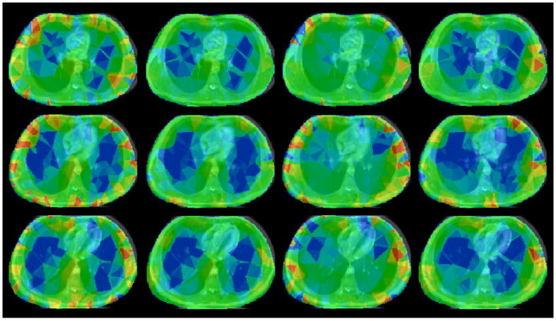
MRI and EIT image co-registration. Left to right columns: Sitting standard reconstruction, sitting shape correction reconstruction, supine standard reconstruction and supine shape correction reconstruction. Top to bottom rows: Transverse slices from superior to inferior.
Figure 8 shows the mutual information with a lung-segmented MR image as a function of the parameter α, for the shape corrected and standard reconstruction in both the sitting and supine positions at maximum inspiration. For comparison, the maximum possible mutual information, that is the mutual information of the lung-segmented MR image with itself, was 1.51 bits. From figure 8 it can be seen for the subject in the sitting position, there is a maximum of mutual information at approximately 1.11 bits for the standard reconstruction algorithm, with α = 3 × 10⁻², and 1.21 bits for the shape corrected reconstruction, with (α, β) = (10−2, 4 × 10⁻²). In the supine position, there is a maximum of mutual information of approximately 1.09 bits for the standard reconstruction algorithm, with α = 3 × 10⁻², and 1.20 bits for the shape corrected reconstruction algorithm, with (α, β) = (2 × 10⁻², 4 × 10⁻²). This corresponds to an approximate 10% increase in the maximal mutual information with the shape correction algorithm. It can also be seen at this particular value of β that the shape corrected reconstruction generally has increased mutual information with the standard reconstruction over a wide range of α. The increase in mutual information from a standard to shape correction reconstruction is also visually evident in the images of figures 4 and 5 (which are reconstructions at (α, β) corresponding to the maximum mutual information), when compared to figure 2a.
Figure 8.
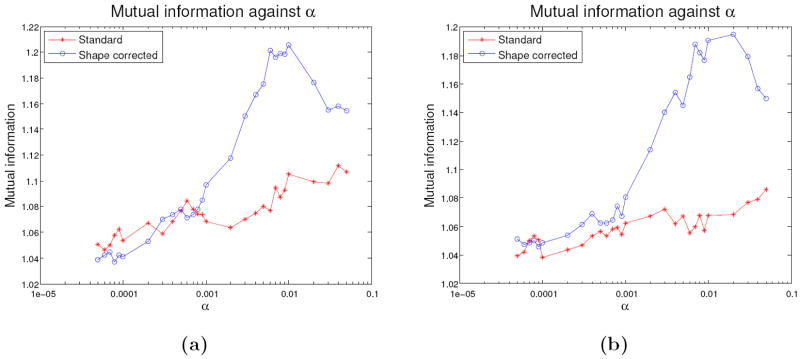
Mutual information parameter study as a function of α; (a) and (b) are for the subject in the sitting and supine position respectively with a shape corrected (β = 4 × 10⁻²) and standard (β = 0) reconstruction.
4. Conclusions and future work
This paper demonstrates results of 3D EIT dynamic lung imaging at Manchester using an array of 32 electrodes with the fEITER system. The implemented shape correction algorithm explicitly accounts for small changes in the boundary shape which occur when the subject breathes. This novel algorithm yields a reduction of boundary artefacts and improved contrast of the lungs when compared to a standard reconstruction algorithm without shape correction. The co-registration process and the use of a mutual information performance criterion presented here provides an effective and practical method of directly comparing the spatial fidelity of EIT images with those obtained from MRI. The shape correction algorithm increased the maximum mutual information with a lung-segmented MR image by approximately 10% for both a subject in the sitting and supine positions and we believe this is the first time mutual information has been used to assess the quality of lung EIT reconstructions. Our findings suggest that shape correction would be a valuable enhancement to the reconstruction algorithms used in existing commercial EIT instruments applied to lung imaging, such as the PulmoVista® 500 system, developed by Dräger (Teschner and Imhoff).
Previous multiple electrode plane studies, such as those by Nebuya et al (2006) and Bikker et al (2011), have typically only used successive EIT data collection at different electrode planes of the chest, resulting in 2D reconstructions of each plane, at low frame rates. One notable exception to this trend is the tomography systems of the Rensselaer group (Cook et al (1994) and Saulnier et al (2007)) which have previously provided 3D lung and pulmonary images, albeit using only generic reconstruction models. Although the MRI-informed 3D reconstruction and high frame rate of our present study address these issues, the use of non-simultaneous data acquisition across the imaging modalities remains a shortcoming as it requires the subject to achieve repeatable breathing and posture for the separate data captures. For better model generation and validation of EIT using MRI, it is thus most attractive to perform simultaneous data acquisition. If EIT were to be routinely used as a bedside monitoring tool, optical tracking techniques could plausibly be used to inform electrode positions and an approximate boundary shape such as those by Forsyth et al (2011) in breast imaging. However, the strength of using MRI to inform the shape is that we can also assess the spatial resolution of EIT after post processing using, for example, mutual information as presented here. Additionally, we note that many patients with serious lung injuries in intensive care units have had MR and/or CT scans during their course of treatment, and so if this information is available it is logical to use this as prior information of the external shapes for the EIT forward and reconstruction finite element models as we have described here.
The present methodology could benefit significantly from improvements in the generation of the thorax model. Firstly, it was found that the resulting image reconstructions were sensitive to the somewhat arbitrary caudal and distal cut-off heights chosen for the model. If the model cut-off height chosen is too small, a non-physical zero current flux boundary condition is set at the caudal and distal ends of the model and the simulated voltages have logarithmic decays associated with a 2D model. We believe this is a major contribution to the twisting effects seen in some image reconstructions, as noted in section 3.3. Choosing a larger cut-off height resulted in little qualitative change in the reconstruction in the electrode planes, and unrealistic conductivity changes far away from the electrode planes. A possible way to compensate for this is to use infinite elements to model the voltage decay at the caudal and distal ends of the model such as by Vauhkonen et al (2000). Secondly, the image reconstructions presented here are 2.5D, in the sense that the model cross section did not vary along the caudal-distal axis. This could be addressed by generating fully 3D models incorporating the electrodes, from either commercial meshing packages such as Simpleware (2013) or open source projects such as iso2mesh (Fang and Boas (2009)). Although demonstrated here for the MRI case, the use of imaging-informed EIT modelling and subsequent co-registration are directly transferable to other high resolution tomographic modalities, most notably CT.
The problems of model dimension and shape described here need to be resolved adequately before repeatable absolute imaging becomes a realistic possibility in thoracic EIT. With the introduction of fully 3D thorax models, we can envisage incorporating more spatial prior information of human tissue and anatomy, such as the liver, heart, ribs and spine into patient-specific thorax reconstruction models, as well as their in-vivo conductivity values (Faes et al (1999)). This would be a further development of the finite difference models developed by Zhang et al (2005). However, these high resolution modelling approaches have not yet had a significant impact in clinical lung EIT. Fully 3D thorax models with anatomy such as the heart included would not only improve the forward problem in lung EIT, but also be important to further improve the image co-registration and mutual information techniques outlined in this work. An assessment of the best prior smoothness constraints on the conductivity, and the voltage data, to offset the ill-posedness of EIT reconstruction, is another topic of paramount importance for absolute lung imaging. The use of classical Tikhonov regularisation presented here, which in the Bayesian viewpoint assumes conductivity changes for all pixels are independent and identically distributed, is somewhat unrealistic and we feel this could be significantly improved by using generalised Tikhonov regularisation and non-smooth penalisation norms.
Supplementary Material
Acknowledgments
This work is funded via the RCUK Science Bridges award, EPSRC Ref: EP/G041733/1, and MIRAN, EPSRC Ref: EP/K00428X/1. Michael Crabb is funded through a Philips Industrial CASE Studentship, EPSRC Ref: EP/H50141X/1. Ron Kikinis is funded through the NIH grants: P41-EB015898, P41-RR013218 and U54-EB005149. All EIT and MRI data collections were performed at the Wolfson Molecular Imaging Centre (WMIC) of the University of Manchester.
Footnotes
The library function ng_mk_extruded_model.m
The library function jacobian_movement_perturb.m
The library function jacobian_adjoint.m
References
- Adler A, et al. GREIT: a unified approach to 2D linear EIT reconstruction of lung images. Physiol Meas. 2009;30:S35–55. doi: 10.1088/0967-3334/30/6/S03. [DOI] [PubMed] [Google Scholar]
- Adler A, et al. Whither lung EIT: where are we, where do we want to go and what do we need to get there? Physiol Meas. 2012;33:679–94. doi: 10.1088/0967-3334/33/5/679. [DOI] [PubMed] [Google Scholar]
- Adler A, Borsic A, Polydorides A, Lionheart WRB. Simple FEMs aren’t as good as we thought: experiences developing EIDORS v3.3. Proc 9th Int Conf EIT; Dartmouth College, New Hampshire. 2008. [Google Scholar]
- Adler A, Guardo R, Berthiaume Y. Impedance imaging of lung ventilation: do we need to account for chest expansion? IEEE Trans Biomed Eng. 1996;43:414–20. doi: 10.1109/10.486261. [DOI] [PubMed] [Google Scholar]
- Adler A, Lionheart WRB. Uses and abuses of EIDORS: An extensible software base for EIT. Physiol Meas. 2006;27:S25–42. doi: 10.1088/0967-3334/27/5/S03. [DOI] [PubMed] [Google Scholar]
- Barber DC, Brown BH. Applied potential tomography. JPE. 1984;17:723–33. [Google Scholar]
- Bikker IG, Preis C, Egal M, Bakker J, Gommers D. Electrical impedance tomography measured at two thoracic levels can visualize the ventilation distribution changes at the bedside during a decremental positive end-expiratory lung pressure trial. Crit Care. 2011;15:R193. doi: 10.1186/cc10354. [DOI] [PMC free article] [PubMed] [Google Scholar]
- Bodenstein M, David M, Markstaller K. Principles of electrical impedance tomography and its clinical application. Crit Care Med. 2009;37:713–24. doi: 10.1097/CCM.0b013e3181958d2f. [DOI] [PubMed] [Google Scholar]
- Cook RD, Saulnier GJ, Gisser DG, Goble JC, Newell JC, Isaacson D. ACT3: a high-speed, high-precision electrical impedance tomograph. IEEE Trans Biomed Eng. 1994;41:713–22. doi: 10.1109/10.310086. [DOI] [PMC free article] [PubMed] [Google Scholar]
- Costa ELV, Lima RG, Amato MBP. Electrical impedance tomography. Curr Opin Crit Care. 2009a;15:18–24. doi: 10.1097/mcc.0b013e3283220e8c. [DOI] [PubMed] [Google Scholar]
- Costa EL, Borges JB, Melo A, Suarez-Sipmann F, Toufen C, Böhm SH, Amato MB. Bedside estimation of recruitable alveolar collapse and hyperdistension by electrical impedance tomography. Intensive Care Med. 2009b;35:1132–37. doi: 10.1007/s00134-009-1447-y. [DOI] [PubMed] [Google Scholar]
- Crabb MG, Davidson JL, Little R, Wright P, Naish JH, Parker GJM, McCann H, Lionheart WRB. Accounting for electrode movement in MRI-informed functional EIT lung imaging. 100 years of electrical imaging; Paris, France. 2012. pp. 83–86. [Google Scholar]
- Dardé J, Hybönen N, Seppänen A, Staboulis S. Simultaneous reconstruction of outer boundary shape and admittivity distribution in electrical impedance tomography. SIAM J Imaging Sci. 2013;6:176–98. [Google Scholar]
- Davidson JL, Little RA, Wright P, Naish J, Kikinis R, Parker GJM, McCann H. Fusion of images obtained from EIT and MRI. Electronics Letters. 2012;48:617–18. [Google Scholar]
- Faes TJC, van der Meij HA, de Munck JC, Heethaar RM. The electrical resistivity of human tissues (100Hz-10MHz): a meta-analysis of review studies. Physiol Meas. 1999;20:R1–10. doi: 10.1088/0967-3334/20/4/201. [DOI] [PubMed] [Google Scholar]
- Fang Q, Boas D. Tetrahedral mesh generation from volumetric binary and gray-scale images. Proc 6th IEEE Int Symp on Biomedical Imaging: From Nano to Macro; Boston. 2009. pp. 1142–45. [Google Scholar]
- Forsyth J, Borsic A, Halter RJ, Hartov A, Paulsen KD. Optical breast shape capture and finite-element mesh generation for electrical impedance tomography. Physiol Meas. 2011;32:797–809. doi: 10.1088/0967-3334/32/7/S05. [DOI] [PMC free article] [PubMed] [Google Scholar]
- Frerichs I. Electrical impedance tomography (EIT) in applications related to lung and ventilation: a review of experimental and clinical activities. Physiol Meas. 2000;21:R1–21. doi: 10.1088/0967-3334/21/2/201. [DOI] [PubMed] [Google Scholar]
- Frerichs I, Hinz J, Herrmann P, Weisser G, Hahn G, Dudykevych T, Quintel M, Hellige G. Detection of local air content by electrical impedance tomography with electron beam CT. J Appl Physiol. 2002;93:660–6. doi: 10.1152/japplphysiol.00081.2002. [DOI] [PubMed] [Google Scholar]
- Frerichs I, Pulletz S, Elke G, Reifierscheid F, Schädler D, Scholz J, Weiler N. Assessment of Changes in Distribution of Lung Perfusion by Electrical Impedance Tomography. Respiration. 2009;77:282–91. doi: 10.1159/000193994. [DOI] [PubMed] [Google Scholar]
- Grychtol B, Lionheart WRB, Bodenstein M, Wolf GK, Adler A. Impact of model shape mismatch on reconstruction quality in electrical impedance tomography. IEEE Trans Med Imaging. 2012;31:1754–60. doi: 10.1109/TMI.2012.2200904. [DOI] [PMC free article] [PubMed] [Google Scholar]
- Hinz J, Gehoff A, Moerer O, Frerichs I, Hahn G, Hellige G, Quintel M. Regional filling characteristics of the lungs in mechanically ventilated patients with acute lung injury. Eur J Anaesthesiol. 2007;24:414–24. doi: 10.1017/S0265021506001517. [DOI] [PubMed] [Google Scholar]
- Hinz J, Neumann P, Dudykevych T, Andersson LG, Wrigge H, Burchardi H, Hedenstierna G. Regional ventilation by electrical impedance tomography: a comparison with ventilation scintigraphy in pigs. Chest. 2003;124:314–22. doi: 10.1378/chest.124.1.314. [DOI] [PubMed] [Google Scholar]
- Ider YZ, Gencer NG, Atalar E, Tosun H. Electrical impedance tomography of translationally uniform cylindrical objects with general cross-sectional boundaries. IEEE Trans Med Imaging. 1990;9:49–59. doi: 10.1109/42.52982. [DOI] [PubMed] [Google Scholar]
- Kaipio JP, Kolehmainen V, Somersalo E, Vauhkonen M. Statistical inversion and Monte Carlo sampling methods in electrical impedance tomography. Inverse Problems. 2000;16:1487–522. [Google Scholar]
- Kolehmainen V, Lassas M, Ola P. The inverse conductivity problem with an imperfectly known boundary in three dimensions. SIAM J Appl Math. 2007;67:1440–52. [Google Scholar]
- Kolehmainen V, Lassas M, Ola P, Siltanen S. Recovering boundary shape and conductivity in electrical impedance tomography. Inverse Problems and Imaging. 2013;7:217–42. [Google Scholar]
- Kunst PW, Noordegraaf AV, Raaijmakers E, Bakker J, Groeneveld AB, Postmus PE, de Vries PM. Electrical impedance tomography in the assessment of extravascular lung water in noncardiogenic acute respiratory failure. Chest. 1999;116:1695–702. doi: 10.1378/chest.116.6.1695. [DOI] [PubMed] [Google Scholar]
- Kunst PWA, Noordegraaf AV, Hoekstra OS, Postmus PE, de Vries PMJM. Ventilation and perfusion imaging by electrical impedance tomography: a comparison with radionuclide scanning. Physiol Meas. 1998;19:481–90. doi: 10.1088/0967-3334/19/4/003. [DOI] [PubMed] [Google Scholar]
- Lionheart WRB. Boundary shape and electrical impedance tomography. Inverse Problems. 1998;14:139–47. [Google Scholar]
- Lionheart WRB. Uniqueness, Shape and Dimension in EIT. Annals of the New York Academy of Sciences. 1999;873:466–71. [Google Scholar]
- Lundin S, Stenqvist O. Electrical impedance tomography: potentials and pitfalls. Curr Opin Crit Care. 2012;18:35–41. doi: 10.1097/MCC.0b013e32834eb462. [DOI] [PubMed] [Google Scholar]
- McCann H, Ahsan ST, Davidson JL, Robinson RL, Wright P, Pomfrett CJD. A portable instrument for high-speed brain function imaging: fEITER. Conf Proc IEEE Eng Med Biol Soc. 2011:7029–32. doi: 10.1109/IEMBS.2011.6091777. [DOI] [PubMed] [Google Scholar]
- McCormick D, Davidson JL, McCann H. Conversion of EIT brain images for co-registration. Proc 8th Int Conf EIT; Graz. 2007. pp. 384–87. [Google Scholar]
- Muders T, Luepschen H, Putensen C. Impedance tomography as a new monitoring technique. Curr Opin Crit Care. 2010;16:269–75. doi: 10.1097/MCC.0b013e3283390cbf. [DOI] [PubMed] [Google Scholar]
- Nebuya S, Noshiro M, Yonemoto A, Tateno S, Brown BH, Smallwood RH, Milnes P. Study of the optimum level of electrode placement for the evaluation of absolute lung resistivity with the Mk3.5 EIT system. Physiol Meas. 2006;27:S129–37. doi: 10.1088/0967-3334/27/5/S11. [DOI] [PubMed] [Google Scholar]
- Nissenen A, Kolehmainen V, Kaipio JP. Reconstruction of domain boundary and conductivity in electrical impedance tomography using the approximation error approach. Int J Uncertainty Quantification. 2011;1:203–22. [Google Scholar]
- Pieper S, Halle M, Kikinis R. 3D SLICER. Proc 1st IEEE Int Symp on Biomedical Imaging: From Nano to Macro; 2004. pp. 632–35. [Google Scholar]
- Pluim JPW, Antoine-Maintz JB, Viergever MA. Mutual-information-based registration of medical images: a survey. IEEE Trans Med Imaging. 2003;22:986–1004. doi: 10.1109/TMI.2003.815867. [DOI] [PubMed] [Google Scholar]
- Polydories N. Image Reconstruction Algorithms for Soft-Field Tomography. UMIST 2002 [Google Scholar]
- Ramachandran P. Mayavi: A free tool kit for CFD data visualization. 4th Annual CFD symposium; Aeronautical Society of India; 2001. http://mayavi.sourceforge.net. [Google Scholar]
- Richard JC, Pouzot C, Gros A, Tourevielle C, Lebars D, Lavenne F, Frerichs I, Guérin C. Electrical impedance tomography compared to positron emission tomography for the measurement of regional lung ventilation: an experimental study. Crit Care. 2009;13:R82. doi: 10.1186/cc7900. [DOI] [PMC free article] [PubMed] [Google Scholar]
- Saulnier GJ, Liu N, Tamma C, Xia H, Kao TJ, Newell JC, Isaacson D. An Electrical Impedance Spectroscopy System for Breast Cancer Detection. Conf Proc IEEE Eng Med Biol Soc; 2007. pp. 4154–57. [DOI] [PubMed] [Google Scholar]
- Schöberl J. NETGEN - An Advancing Front 2D/3D-Mesh Generator Based On Abstract Rules. Comput Visual Sci. 1997;1:41–52. [Google Scholar]
- Simpleware Ltd. ScanIP, +ScanFE and +ScanCAD software v 6.0 reference guide. Exeter UK: Innovation Centre; 2013. http://www.simpleware.com. [Google Scholar]
- Smit HJ, Noordegraaf AV, Marcus JT, van der Weijden A, Postmus P, de Vries PM, Boonstra A. Pulmonary vascular responses to hypoxia and hyperoxia in healthy volunteers and COPD patients measured by electrical impedance tomography. Chest. 2003;123:1803–9. doi: 10.1378/chest.123.6.1803. [DOI] [PubMed] [Google Scholar]
- Soleimani M, Gómez-Laberge, Adler A. Imaging of conductivity changes and electrode movement in EIT. Physiol Meas. 2006;27:S103–13. doi: 10.1088/0967-3334/27/5/S09. [DOI] [PubMed] [Google Scholar]
- Somersalo E, Cheney M, Isaacson D. Existence and uniqueness for electrode models for electric current computed tomography. SIAM J Appl Math. 1992;52:1023–40. [Google Scholar]
- Teschner E, Imhoff M. Electrical Impedance Tomography: The realization of regional ventilation monitoring. Dräger; Lübeck Germany: http://www.draeger.com. [Google Scholar]
- Vauhkonen PJ, Vauhkonen M, Kaipio JP. Errors due to the truncation of the computational domain in static three-dimensional electrical impedance tomography. Physiol Meas. 2000;21:125–35. doi: 10.1088/0967-3334/21/1/316. [DOI] [PubMed] [Google Scholar]
- Victorino, et al. Imbalances in regional lung ventilation: a validation study on electrical impedance tomography. Am J Respir Crit Care Med. 2004;169:791–800. doi: 10.1164/rccm.200301-133OC. [DOI] [PubMed] [Google Scholar]
- Zhang J, Patterson RP. EIT images of ventilation: what contributes to the resistivity changes? Physiol Meas. 2005;26:S81–92. doi: 10.1088/0967-3334/26/2/008. [DOI] [PubMed] [Google Scholar]
- Zhao Z, Steinmann D, Frerichs I, Guttman J, Möller K. PEEP titration guided by ventilation homogeneity: a feasibility study using electrical impedance tomography. Crit Care. 2010;14:R8. doi: 10.1186/cc8860. [DOI] [PMC free article] [PubMed] [Google Scholar]
Associated Data
This section collects any data citations, data availability statements, or supplementary materials included in this article.


