Abstract

A photochemical modification of melt-extruded polymeric nanofibers is described. A bioorthogonal functional group is used to decorate fibers made exclusively from commodity polymers, covalently attach fluorophores and peptides, and direct cell growth. Our process begins by using a layered coextrusion method, where poly(ε-caprolactone) (PCL) nanofibers are incorporated within a macroscopic poly(ethylene oxide) (PEO) tape through a series of die multipliers within the extrusion line. The PEO layer is then removed with a water wash to yield rectangular PCL nanofibers with controlled cross-sectional dimensions. The fibers can be subsequently modified using photochemistry to yield a “clickable” handle for performing the copper-catalyzed azide–alkyne cycloaddition (CuAAC) reaction on their surface. We have attached fluorophores, which exhibit dense surface coverage when using ligand-accelerated CuAAC reaction conditions. In addition, an RGD peptide motif was coupled to the surface of the fibers. Subsequent cell-based studies have shown that the RGD peptide is biologically accessible at the surface, leading to increased cellular adhesion and spreading versus PCL control surfaces. This functionalized coextruded fiber has the advantages of modularity and scalability, opening a potentially new avenue for biomaterials fabrication.
Polymeric materials have become ubiquitous in regenerative medicine as scaffolds for cell-seeding, where they have found application in the induction of cellular adhesion, proliferation, and differentiation.1−4 Nanofibrous scaffolds are of particular use as they are porous, allowing transport of nutrients and waste products, have high surface area to volume ratios, and can provide directed cell growth based on fiber alignment.2,5−9 Primarily polymeric nanofibers are fabricated by electrospinning, yielding submicrometer fibers from a diverse range of polymeric materials.10−14 Such systems have been used in regenerative medicine, but also in fields as diverse as nanocomposite materials, simulated cancer environments, filtration membranes, and semiconductors, among many others.15−19 Synthetic fibers for regenerative medicine are often composed of polyesters, usually poly(lactic acid) (PLA), poly(lactic-co-glycolic acid) (PLGA), or poly(ε-caprolactone) (PCL),11,20,21 due to their degradability via hydrolytic pathways and resultant nontoxic byproducts. However, most polymeric scaffolds are unable to promote biological effects, as synthetic polymers do not possess the biochemical cues that are necessary to impact a cell’s fate.
Modification of polyester fibers typically relies on the degradation of the polymer chains, either through hydrolysis to expose carboxylic acids and alcohols20 or through aminolysis to expose a secondary functional group off of the amine.22,23 Both of these routes induce polymer degradation, potentially resulting in reduced mechanical properties and increased erosion of the fibers. Recent work has aimed to ameliorate degradative functionalization through the synthesis of reactive telechelic polymers. These polymers could be processed into a scaffold and then chemically modified. Becker and co-workers have introduced both a strained alkyne for copper-free “click” chemistry24−26 or an azide27 for traditional copper-catalyzed azide–alkyne cycloaddition chemistry (CuAAC) prior to processing of the polymers into fibers. These polymers were processed via electrospinning and could then be decorated using peptides, fluorophores, and gold nanoparticles. However, we aimed to use commodity polymers (i.e., PCL) in a continuous extrusion process to fabricate nanofibers, which can then be nondestructively modified after processing. This strategy is pursued to exploit the scalability of the processing technique using solely commercially available polymers, PCL and poly(ethylene oxide) (PEO), to form the fibrous scaffold. The process is solvent-free and therefore has reduced cost and toxicity compared to conventional solvent-based processing techniques, such as electrospinning. Our technique only uses polymers commonly used in FDA-approved applications during processing, making it ideal for biological applications. The fabrication procedure adopted here is inherently flexible because the extrusion line is composed of several basic configurable units, the multipliers. Arrangement of these multipliers allows control over the number and composition, as well as the dimensions, of fibers. The rectangular cross-section of the extruded nanofibers creates higher surface area to volume ratios when compared to cylindrical fibers. The increased surface area should allow for a higher concentration of surface modifications to be available on the fiber, potentially improving the display of biochemical cues. Additionally, this technique is extremely versatile, allowing processing of other biologically relevant polymers (i.e., PLA or PLGA), assuming that a viscosity match can be found between these other polyesters and PEO.
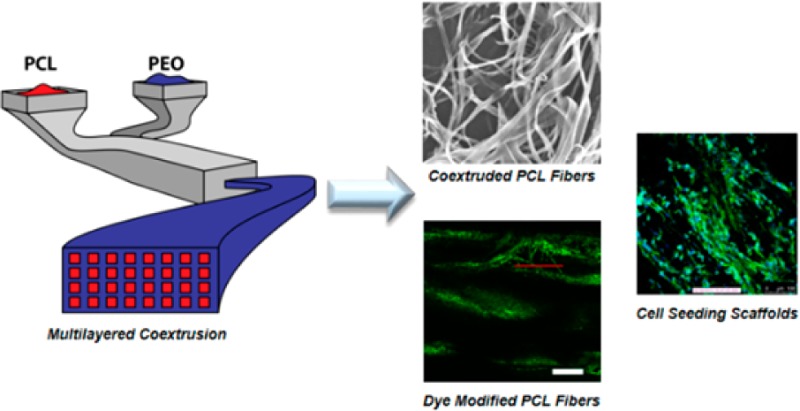
In this work, we used a commercially relevant polymer processing technique, melt coextrusion, in conjunction with a modular chemistry to yield polyester nanofibers with pendant surface functionality. The coextrusion process has been recently reported and will be briefly described here.28 The processing method makes use of the coextrusion of PCL and PEO through a series of die multipliers to form a tape composed of PCL nanofibers arranged and embedded in a PEO matrix. PCL and PEO are melt-pumped and layered on top of one another in the extrusion line (Figure 1). From here a vertical multiplier is used to rearrange the extrudate to yield a vertical-bilayered structure (step A). This initial layering process is then followed by a series of vertical multiplications. Each of the multipliers cuts the flow horizontally, and these two flows are redirected and recombined side-by-side. Finally, the multiplier expands the two flow fields in the vertical direction while compressing them horizontally to double the number of vertical layers. This process is repeated eight times to yield a vertically aligned, layered flow composed of 1024 alternating PCL (512 layers) and PEO (512 layers) layers (step B). The tape is then combined with two surface layers of PEO on the top and bottom (step C) and is extruded through a horizontal multiplier, which has an identical structural design as the vertical multiplier, but is assembled in the extrusion line rotated 90°. In each horizontal multiplication, the melt flow is split vertically, and the two flow fields are stacked with one side on top of the other (2×) to yield PCL nanofibers embedded in a PEO tape. This procedure is repeated one additional time, producing an extrudate tape containing 512 PCL nanodomains embedded in a PEO matrix (step D). Typically, we are able to process 3 pounds of polymer per hour into the PCL/PEO composite tape; this is far in excess of laboratory-scale electrospinning setups (mL/h) and also in excess of industrial electrospinning instruments, whose reported yields are ∼0.4 lbs/h.29 The PEO in the tape can be removed by dissolution in a water bath (24 h) or by using a high pressure water jet (5 min) to produce a PCL nanofiber matrix. A scanning electron micrograph (SEM) of the PCL fibers after the dissolving procedure shows fibers displaying cross-sectional dimensions of approximately 620 ± 130 nm by 4.39 ± 1.3 μm (Figures 1 and S1), as determined by statistical analysis of the length and width dimensions via SEM. Hence, the extruded fibers have ribbon-like morphology rather than traditional cylindrical fibers. Both dissolution in water and the jet procedure produce fibers that are of identical dimensions and morphology via SEM. The dimensions and porosity of these fibers can be controlled via uniaxial orientation or through a rearrangement of the multipliers to further decrease the cross-sectional dimensions, although the focus of this study is the chemical modification of the PCL fibers. After removal of the PEO matrix, <1% of PEO remained, as determined by NMR and DSC (Supporting Information), yielding PCL nanofibers.
Figure 1.

Schematic of coextrusion and two-dimensional multiplication system for producing nanofibers (top). Scanning electron micrograph of the as-extruded PCL/PEO composite tape (bottom left) and PCL nanofibers following PEO dissolution (bottom right). Scale bar: left = 200 μm, right = 20 μm.
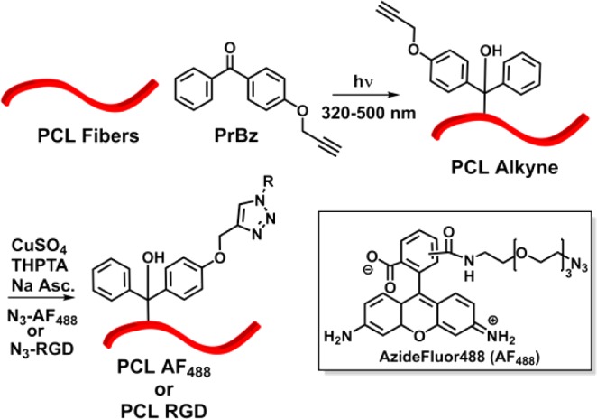
Once the PCL fibers were extruded and separated, pendant functionality was introduced via a modular surface modification approach. A number of papers have focused on the aminolysis of polyester fibers, in which a bifunctional amine is used to introduce a reactive group for further derivatization.22,23 In the case of the extruded nanofibers, prepared as described, the aminolysis reaction using either propargylamine or hexamethylene diamine showed minimal surface modification under mild reaction conditions. Rather than pursuing forcing reaction conditions with excess amine or heating, an alternate route was chosen, which minimizes degradation of the polymer chains within the fibers. As such, a photochemical radical reaction was employed to perform a C–H bond insertion into the backbone of the PCL polymer chains (Scheme 1). Benzophenone is commonly used to perform photochemical C–H insertions and has been previously used to modify PCL surfaces.30,31 The reported modification technique could be easily transitioned to modify other biologically relevant polymers. Propargyl benzophenone (PrBz) was prepared in high yield by reacting 4-hydroxyl benzophenone with propargyl bromide under basic conditions.32 PCL fibers were immersed in a concentrated solution of propargyl benzophenone in methanol and allowed to dry, irradiated via UV (33.2 mW/cm2, 30 min on each side, 320–500 nm), and washed with methanol to yield alkyne-decorated PCL nanofibers. The surface-presented propargyl groups could then be used in the CuAAC reaction to decorate the fiber with any azide containing molecule. To investigate the UV degradation of PCL fibers after modification, we compared the molecular weight and mechanical properties of as-extruded PCL fibers and PCL-alkyne after irradiation with UV light. Gel permeation chromatrography indicates that before and after UV treatment, the molecular weight and dispersity of PCL are essentially identical (Figure S4). Additionally, tensile testing was performed to determine the mechanical properties of the fiber after irradiation. The results indicate that fibers before and after photochemical modification have similar moduli and tensile strength (Figure S5).
Scheme 1. Chemical Scheme for Modification of PCL Nanofibers.

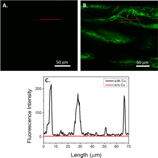
To probe the CuAAC chemistry, we first modified the PCL-alkyne fibers with an azide containing fluorescent dye, AzideFluor488 (AF488). The fibers were modified using aqueous conditions optimized for the ligand-accelerated CuAAC reaction, using tris(3-hydroxypropyltriazolylmethyl)amine (THPTA) as the ligand to accelerate the reaction.33−35 After the CuAAC reaction, upon visual inspection, the fibers were noticeably red after using standard reaction conditions. In the absence of copper, there was no visible change that could be attributed to a hydrophobic physical adsorption of the dye onto the fiber. To further investigate the surface coverage of the PCL fibers, confocal fluorescence microscopy was used to qualitatively and quantitatively evaluate fluorescence intensity of the fibers. As observed in the absence of the copper catalyst, negligible fluorescence is visible in the micrograph (Figure 2A), indicating that little dye nonspecifically adsorbs to the extruded PCL fiber bundle. However, in the presence of copper, a significant fluorescent signal appears in the micrograph, indicating that the chemistry is specific, rather than simple adsorption (Figure 2B). When fluorescence intensity was quantified, modified fibers showed approximately two orders of magnitude higher fluorescence intensity relative to control fibers (Figure 2C). In order to affect biological outcomes, it is necessary that a significant surface coverage of the fibers be attained. To quantify this, we determined both the total dye loading of the fibers in conjunction with surface area measurements. Multipoint Brunauer–Emmett–Teller (BET) measurements were used to determine the surface area of the extruded fibers,36 and UV–visible measurements were used to quantify dye loading. The BET technique relies on the surface adsorption of gas molecules; the total mass of the gas adsorbed allows one to calculate the area of the surface. BET measurements were carried out using krypton gas, revealing a surface area of 41.2 cm2/mg of fiber. For comparison, we fabricated electrospun PCL fibers with fiber dimensions of ∼2 μm, averaging the width and thickness dimensions of the extruded nanofibers. BET measurements were conducted on the electrospun fibers, where the surface area was 6.0 cm2/mg, leaving the extruded rectangular fibers approximately 1 order of magnitude higher in surface area than their cylindrical counterparts. This high surface area can be attributed to the rectangular geometry of the extruded fiber as compared to an electrospun cylindrical fiber. Once the surface area was determined, the PCL fibers were labeled with AF488, as described. The fibers were dissolved in dichloromethane, and the absorbance at 501 nm was compared to a standard curve of AF488 to determine total surface loading of the fibers. The PCL-AF488 fibers were decorated with approximately 15.5 nmol/mg of fiber, resulting in a surface coverage of 0.38 nmol/cm2. This level of surface coverage gives strong indications that sufficient densities would be obtained for biological relevance, providing that bioactive cues are available to interact with the surface of cells.
Figure 2.

Fluorescence confocal micrographs of PCL nanofibers. (A) PCL extruded nanofiber control with no CuSO4 added during reaction with AF488. Scale bar = 50 μm. (B) PCL after the CuAAC reaction with AF488, including CuSO4. Scale bar = 50 μm. (C) Fluorescent intensity in the region of interest, as indicated by the red lines in images A and B. The red line on the graph corresponds to image A, and the black line is indicative of B.
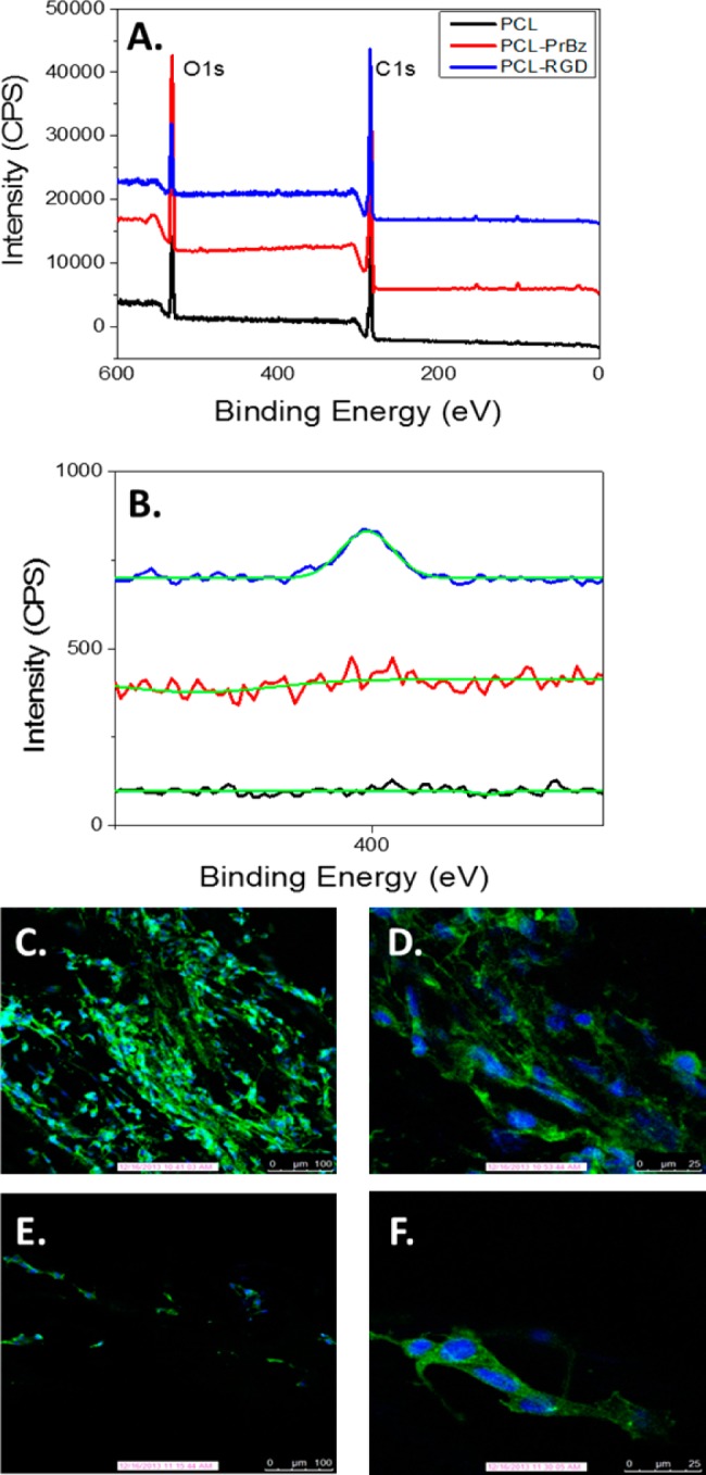
The surface coverage of the fibers is of particular importance as a scaffold for regenerative medicine. A common peptide, and one we employed here, is the RGD motif. RGD sequences bind to integrin receptors and, when immobilized on a surface, can lead to cell adhesion and spreading, a key feature for tissue engineering scaffolds. Previous work showed that low pM/cm2 surface coverages of RGD peptides on polymeric surfaces were sufficient to promote cell adhesion.1,37,38 The concentrations on the PCL nanofibers are three orders of magnitude higher than those necessary for adhesion, representing a viable scaffold to present biochemical cues and for cell-seeding. Therefore, we sought to adhere an RGD peptide to promote cellular adhesion onto the PCL fiber scaffold. We first synthesized an RGD peptide with an N-terminal azide group (N3-GRGDSPDG),39 for attachment to the propargyl PCL fiber. The RGD peptide motif was chosen for its ability to promote adhesion through the interaction with cell surface integrin receptors, as is known to occur with NIH3T3 fibroblasts, a common model for cell-seeding in regenerative medicine.40,41 The same scheme of photochemical attachment of propargyl-benzophenone followed by CuAAC reaction was used to introduce the RGD-azide onto the surface of the PCL fibers. The attachment of the azido-peptide was confirmed via X-ray photoelectron spectroscopy (XPS), where the modified fiber showed a significant nitrogen peak (N1s), as would be expected for peptide-modified fibers. In the control experiments, no nitrogen peak was observed upon analysis of the PCL or PCL-benzophenone surfaces (Figure 3B). XPS surface analysis indicated an approximate surface coverage of 2% by mass, consistent with our results using the fluorescent azide.
Figure 3.

PCL-RGD Fibers. (A) Full XPS spectrum of PCL, PCL-PrBz, and PCL-RGD. (B) N1s XPS spectrum of PCL nanofibers (black) and PCL-RGD fibers (blue). (C) Confocal fluorescence microscopy image of NIH3T3 cells after 72 h of growth on PCL-RGD scaffold; 10× objective. (D) Confocal fluorescence microscopy image of NIH3T3 cells after 72 h of growth on PCL-RGD scaffold; 40× objective. (E) Confocal fluorescence microscopy image of NIH3T3 cells after 72 h of growth on control PCL scaffold; 10× objective. (F) Confocal fluorescence microscopy image of NIH3T3 cells after 72 h of growth on control PCL scaffold; 40× objective. Blue indicates DAPI stain and green indicates actin green stain in confocal micrographs.
PCL-RGD nanofibers were used as a cell seeding scaffold that would be able to promote adhesion, growth, and proliferation of NIH3T3 fibroblasts. Both PCL and PCL-RGD extruded fibers were immobilized on a glass slide, and NIH3T3 cells were deposited onto the fiber. Following 72 h of incubation, cells were fixed, permeabilized, and stained using actin green and 4′,6-diamidino-2-phenylindole (DAPI). The slides were visualized via fluorescence confocal microscopy (Figure 3). The actin stain is shown in green and is based on a fluorescently labeled phalloidin, which binds to actin filaments in the cells allowing visualization of the cytoskeleton. DAPI is seen in blue and indicates staining of the cell nuclei. After 72 h, a much greater portion of the cells adhered to the fibers, as visualized by confocal microscopy. Additionally, the RGD-immobilized fibers provided enhanced cell spreading, as visualized by the actin filaments within the cells. At 72 h postseeding, the cells became elongated along the axis of the fiber, and a clear enhancement of cell density was observed by inspection of confocal micrographs (Figure 3C,D). In comparison, the unmodified PCL fibers showed very little adhesion and spreading after 72 h. To quantify viability of the cells on the modified and unmodified PCL fiber scaffold, an MTT assay was used.
After 72 h of incubation, the fibers were removed from the slides and immersed in MTT containing media. The PCL-RGD fibers showed an approximate increase of 60% cell viability (Figure S6) relative to the PCL fibers alone after 72 h of incubation. These results indicates that the PCL-RGD fibers maintained the biological activity of the peptide in sufficient concentrations to promote adhesion, elongation, and proliferation. In addition, the cells spread along the axis of the fibers, indicating cellular orientation. While SEM images show microscopic entanglement of the fibers, macroscopically there is enough alignment to promote directed cell growth.
In summary, we report the chemical modification of a continuously processed nanofibrous biomaterial comprised solely from commodity polymers. The processing technique is solvent free, scalable, uses polymers that have many FDA-approved applications and allows for the simple tuning of cross-sectional dimensions of the fiber. To convert this scaffold into a biological material, we utilized photochemistry to introduce an alkyne onto the surface of the fibers. This functional group allows for the modular synthesis of a host of chemically derivatized fibers by employing the CuAAC reaction. A densely covered surface was obtained using this technique, and more importantly, the biological activity of the RGD peptide remained intact, promoting cellular adhesion and spreading. In the future, we plan to further increase the chemical complexity of these nanofibrous PCL mats as tissue engineering scaffolds.
Acknowledgments
J.K.P. acknowledges the National Science Foundation (NSF) Center for Layered Polymeric Systems for start-up funds (DMR 0423914) and generous use of the center’s confocal microscope, as well as a NIH Pathway to Independence Award for funding (R00EB011530). E.B. and L.T.J.K. acknowledge funding from the NSF (DMR 0423914 (E.B., L.T.J.K.) and CMMI 1335276 (L.T.J.K.)). Prof. Horst von Recum is thanked for the donation of the NIH3T3 cells, and Jack Edelbrock is thanked for his assistance in figure making. L.T.J.K. also acknowledges funding from the Defense University Research Instrumentation Program (Grant W911NF1110343).
Supporting Information Available
Experimental details for the coextrusion process, synthetic procedures, surface area measurements, and tissue culture conditions and assays. This material is available free of charge via the Internet at http://pubs.acs.org.
The authors declare no competing financial interest.
Funding Statement
National Institutes of Health, United States
Supplementary Material
References
- Hersel U.; Dahmen C.; Kessler H. Biomaterials 2003, 24, 4385–4415. [DOI] [PubMed] [Google Scholar]
- Liu W.; Thomopoulos S.; Xia Y. Adv. Healthcare Mater. 2012, 1, 10–25. [DOI] [PMC free article] [PubMed] [Google Scholar]
- Dongargaonkar A. A.; Bowlin G. L.; Yang H. Biomacromolecules 2013, 14, 4038–4045. [DOI] [PMC free article] [PubMed] [Google Scholar]
- McClure M. J.; Simpson D. G.; Bowlin G. L. J. Mech. Behav. Biomed. Mater. 2012, 10, 48–61. [DOI] [PubMed] [Google Scholar]
- Choi J. S.; Choi S. H.; Yoo H. S. J. Mater. Chem. 2011, 21, 5258–5267. [Google Scholar]
- Rieger K. A.; Birch N. P.; Schiffman J. D. J. Mater. Chem. B 2013, 1, 4531–4541. [DOI] [PubMed] [Google Scholar]
- Barnes C. P.; Sell S. A.; Boland E. D.; Simpson D. G.; Bowlin G. L. Adv. Drug Delivery Rev. 2007, 59, 1413–1433. [DOI] [PubMed] [Google Scholar]
- Sisson K.; Zhang C.; Farach-Carson M. C.; Chase D. B.; Rabolt J. F. J. Biomed. Mater. Res., Part A 2010, 94A, 1312–1320. [DOI] [PubMed] [Google Scholar]
- Sisson K.; Zhang C.; Farach-Carson M. C.; Chase D. B.; Rabolt J. F. Biomacromolecules 2009, 10, 1675–1680. [DOI] [PubMed] [Google Scholar]
- Cipitria A.; Skelton A.; Dargaville T. R.; Dalton P. D.; Hutmacher D. W. J. Mater. Chem. 2011, 21, 9419–9453. [Google Scholar]
- Dias J.; Gloria A.; Bártolo P. J. Adv. Mater. Res. 2013, 683, 137–140. [Google Scholar]
- Liu W.; Ni C.; Chase D. B.; Rabolt J. F. ACS Macro Lett. 2013, 2, 466–468. [DOI] [PubMed] [Google Scholar]
- Li K.; Mao B.; Cebe P. J. Therm. Anal. Calorim. 2014, 116, 1351–1359. [Google Scholar]
- Yu L.; Cebe P. Polymer 2009, 50, 2133–2141. [Google Scholar]
- Wanasekara N. D.; Stone D. A.; Wnek G. E.; Korley L. T. J. Macromolecules 2012, 45, 9092–9099. [Google Scholar]
- Stone D. A.; Wanasekara N. D.; Jones D. H.; Wheeler N. R.; Wilusz E.; Zukas W.; Wnek G. E.; Korley L. T. J. ACS Macro Lett. 2012, 1, 80–83. [DOI] [PubMed] [Google Scholar]
- Hartman O.; Zhang C.; Adams E. L.; Farach-Carson M. C.; Petrelli N. J.; Chase B. D.; Rabolt J. F. Biomacromolecules 2009, 10, 2019–2032. [DOI] [PMC free article] [PubMed] [Google Scholar]
- Canesi E. V.; Luzio A.; Saglio B.; Bianco A.; Caironi M.; Bertarelli C. ACS Macro Lett. 2012, 1, 366–369. [DOI] [PubMed] [Google Scholar]
- Ma H.; Burger C.; Hsiao B. S.; Chu B. ACS Macro Lett. 2012, 1, 723–726. [DOI] [PubMed] [Google Scholar]
- Ghasemi-Mobarakeh L.; Prabhakaran M. P.; Morshed M.; Nasr-Esfahani M. H.; Ramakrishna S. Mater. Sci. Eng., C 2010, 30, 1129–1136. [Google Scholar]
- Hartman O.; Zhang C.; Adams E. L.; Farach-Carson M. C.; Petrelli N. J.; Chase B. D.; Rabolt J. F. Biomaterials 2010, 31, 5700–5718. [DOI] [PMC free article] [PubMed] [Google Scholar]
- Zhu Y.; Gao C.; Liu X.; Shen J. Biomacromolecules 2002, 3, 1312–1319. [DOI] [PubMed] [Google Scholar]
- Zhu Y.; Mao Z.; Gao C. RSC Adv. 2013, 3, 2509–2519. [Google Scholar]
- Smith Callahan L. A.; Xie S.; Barker I. A.; Zheng J.; Reneker D. H.; Dove A. P.; Becker M. L. Biomaterials 2013, 34, 9089–9095. [DOI] [PubMed] [Google Scholar]
- Zheng J.; Liu K.; Reneker D. H.; Becker M. L. J. Am. Chem. Soc. 2012, 134, 17274–17277. [DOI] [PubMed] [Google Scholar]
- Zheng J.; Xie S.; Lin F.; Hua G.; Yu T.; Reneker D. H.; Becker M. L. Polym. Chem. 2013, 4, 2215–2218. [Google Scholar]
- Lancuški A.; Fort S.; Bossard F. ACS Appl. Mater. Interfaces 2012, 4, 6499–6504. [DOI] [PubMed] [Google Scholar]
- Wang J.; Langhe D.; Ponting M.; Wnek G. E.; Korley L. T. J.; Baer E. Polymer 2014, 55, 673–685. [Google Scholar]
- Persano L.; Camposeo A.; Tekmen C.; Pisignano D. Macromol. Mater. Eng. 2013, 298, 504–520. [Google Scholar]
- Prucker O.; Naumann C. A.; Rühe J.; Knoll W.; Frank C. W. J. Am. Chem. Soc. 1999, 121, 8766–8770. [Google Scholar]
- Chen M.; Besenbacher F. ACS Nano 2011, 5, 1549–1555. [DOI] [PubMed] [Google Scholar]
- Temel G.; Aydogan B.; Arsu N.; Yagci Y. Macromolecules 2009, 42, 6098–6106. [Google Scholar]
- Hong V.; Presolski S.; Ma C.; Finn M. Angew. Chem., Int. Ed. 2009, 48, 9879–9883. [DOI] [PMC free article] [PubMed] [Google Scholar]
- Pokorski J. K.; Breitenkamp K.; Liepold L. O.; Qazi S.; Finn M. G. J. Am. Chem. Soc. 2011, 133, 9242–9245. [DOI] [PMC free article] [PubMed] [Google Scholar]
- Pokorski J. K.; Hovlid M. L.; Finn M. G. ChemBioChem 2011, 12, 2441–2447. [DOI] [PMC free article] [PubMed] [Google Scholar]
- Brunauer S.; Emmett P. H.; Teller E. J. Am. Chem. Soc. 1938, 60, 309–319. [Google Scholar]
- Lagunas A.; Comelles J.; Martínez E.; Prats-Alfonso E.; Acosta G. A.; Albericio F.; Samitier J. Nanomed. Nanotechnol. Biol. Med. 2012, 8, 432–439. [DOI] [PubMed] [Google Scholar]
- Chollet C.; Chanseau C.; Remy M.; Guignandon A.; Bareille R.; Labrugère C.; Bordenave L.; Durrieu M.-C. Biomaterials 2009, 30, 711–720. [DOI] [PubMed] [Google Scholar]
- Tschopp J. F.; Mazur C.; Gould K.; Connolly R.; Pierschbacher M. D. Thromb. Haemost. 1994, 72, 119–124. [PubMed] [Google Scholar]
- Guarnieri D.; De Capua A.; Ventre M.; Borzacchiello A.; Pedone C.; Marasco D.; Ruvo M.; Netti P. A. Acta Biomater. 2010, 6, 2532–2539. [DOI] [PubMed] [Google Scholar]
- Causa F.; Battista E.; Della Moglie R.; Guarnieri D.; Iannone M.; Netti P. A. Langmuir 2010, 26, 9875–9884. [DOI] [PubMed] [Google Scholar]
Associated Data
This section collects any data citations, data availability statements, or supplementary materials included in this article.


