Abstract
Ceramic prostheses are subject to sliding contact under normal and tangential loads. Accurate prediction of the onset of fracture at two contacting surfaces holds the key to greater long-term performance of these prostheses. In this study, building on stress analysis of Hertzian contact and considering fracture criteria for linear elastic materials, a constitutive fracture mechanics relation was developed to incorporate the critical fracture load with the contact geometry, coefficient of friction and material fracture toughness. Critical loads necessary to cause fracture under a sliding indenter were calculated from the constitutive equation, and compared with the loads predicted from elastic stress analysis in conjunction with measured critical load for frictionless normal contact—a semi-empirical approach. The major predictions of the models were calibrated with experimentally determined critical loads of current and future dental ceramics after contact with a rigid spherical slider. Experimental results conform with the trends predicted by the models.
Keywords: Sliding contact fracture, Friction, Toughness, Dental ceramics, Functionally graded ceramics
1. Introduction
Ceramics possess many excellent characteristics, including high hardness, high melting point, excellent corrosion resistance and, potentially, low friction and low wear. In addition, ceramics can be derived from rocks and minerals, which make up about 25% of the Earth’s crust compared with 1% for all metals [1]. Thus, ceramics have been perceived as the materials of the future, and have proved to be the current choice of material in a wide range of demanding applications. Some examples, among many others, are prosthetic devices for dental and medical applications, insulators for electronic applications, and mechanical seals and ball bearings for an array of engineering applications. However, in dental and medical prostheses, premature failure still remains a major concern and, in many cases, has been linked to excessive material loss and/or fracture [2–11].
The initiation of microcracks at two contacting surfaces of structural components is a phenomenon that bears on several problems of practical significance, such as a transition to rapid material loss (severe wear) and the onset of strength degradation (fracture). Therefore, there has been a large volume of literature concerning contact problems in brittle solids. The field of contact mechanics may have started in 1882 with a seminal publication by Hertz [12]. The original Hertz theory is restricted to frictionless contact between two elastic bodies. Over the past century, progress has been made to extend the Hertz theory to more realistic problems— frictional contact of two elastic solids in sliding or rolling contact [13–19]. A simple scheme—a blunt slider pressed against a flat surface—has been developed to elucidate the fracture behavior of brittle solids subjected to frictional contact [16,20]. While simple, such a scheme closely represents occlusal contacts between opposing dentitions [21–24], and is readily amenable to fracture mechanics analysis.
Most of the early studies on sliding contact tended to focus on the stress analysis of elastic fields [13–16,19]. Theory predicts that, for complete slip, the presence of a tangential force intensifies the stresses around the contact circle, and the maximum tensile stress occurs at the trailing edge of the indenter [19,25]. Thereby, the normal load needed to generate a fracture is projected to be significantly reduced under frictional sliding relative to frictionless normal loading [16,19]. However, such stress analysis can only predict where a crack is most likely to form, based on the location of maximum tensile stress. It does not specify when the cracks initiate. Prediction of critical fracture load remains a challenge.
Since the stresses in a brittle material beneath a blunt indenter remain elastic up to the point of fracture, linear elastic fracture mechanics may be applied to predict the fracture load. The first attempt to apply fracture mechanics to the Hertzian sliding contact problem was made in 1967 by Lawn [17]. Since then, several theoretical models have been developed to predict the critical load for crack initiation under sliding contact using fracture mechanics [25–29]. By relating the strain energy release rate to the stress intensity factor, it is possible to estimate the critical load for the onset of sliding fracture in elastic solids [28,29]. The central difficulty in such an approach is that the high stress gradients near the contact circle and the introduction of a small initial crack can further complicate the matter. It is, therefore, not surprising that the mathematical treatment is complex and is not amenable to accurate first-principles evaluation [25,30,31].
There have been a number of experimental studies on brittle fracture under sliding contact [17,20,25,32–37]. Most studies have focused on model brittle materials such as glass, alumina and zirconia. There have not been any systematic investigations into the sliding fracture resistance of dental ceramics.
In this study, based on the Hertzian stress field, assuming cracks form at the same tensile stress under normal loading as when sliding, and using the fracture mechanics approach of Lawn [31], the present authors have derived a simple constitutive relation to predict fracture of brittle materials under sliding. The constitutive equation has established a fracture mechanics relation between the fracture load and indenter radius, with the friction coefficient and material toughness the governing properties. The theory was then calibrated against experiment, where Hertzian indentation tests have been conducted on a variety of commercial and in-house developed dental ceramics under sliding and normal loads in water. It was found that this simple constitutive relation works very well in predicting the resistance to sliding contact fracture of ceramics with insignificant R-curve behavior and homogeneous microstructures.
2. Contact mechanics
2.1. Elasticity model of stress analysis
The present study first considers the simpler case of a hard spherical indenter loaded normally on the flat face of an isotropic brittle solid. The stresses at any point throughout the solid were calculated by Huber [13] and discussed extensively by Johnson [18] and Lawn [38]. Here, the focus is on the distribution of the tensile stress component responsible for the formation of ring cracks. Following the analysis by Johnson [18] and Lawn [38], the maximum tensile stress σm occurs at the contact circle in the specimen surface and is given by
| (1) |
where v is the Poisson’s ratio of the specimen, P is the normal load, and a is the contact radius.
Consider a rigid spherical indenter carrying a normal load Pn, which slides over the flat surface of a brittle solid with a constant velocity. This sliding motion, or any tendency to slide, introduces a tangential force of friction Q, acting on each surface, in a direction opposite to the motion. According to Amontons’ law of friction [39], formulated in 1699, the frictional (tangential) force Q is linearly proportional to the applied normal load Pn
| (2) |
where μ is the coefficient of friction.
The question here is the effect of the tangential force Q on the contact stresses. Building on a method introduced by Green [40] for the stress analysis of a normally loaded half-space, Hamilton and Goodman [16] and later Hamilton [19], then Sackfield and Hills [41], derived explicit equations for calculating the stress field in the solid for the case of complete slip. In this configuration, the maximum radial tensile stress σsm occurs at the trailing edge of the moving indenter and is enhanced dramatically relative to that under the normal load
| (3) |
where Pn is the applied normal load during the sliding action. The first term in brackets represents the stress due to the normal load, while the second term signifies the added stress due to the friction.
If cracks form at the same tensile stress under normal loading as when sliding, and since a∝P1/3 (i.e. the contact radius is proportional to the reciprocal cube of the applied load), the critical normal load Pn for the onset of fracture in sliding can be related to the critical load P for fracture under frictionless normal loading [20,34]
| (4) |
and
| (5) |
In sliding, the cracks are no longer complete circles, but have the shape of a series of horseshoes, often referred to as herringbone cracks. Eqs. (4) and (5) connect quantitatively the normal and sliding contact between a sphere and a planar surface.
While the above stress analysis provides information on where the maximum tensile stress is, it only indicates where a crack could form. Therefore, if one uses Eq. (4) to predict the critical normal load Pn for the onset of fracture in sliding, the critical load P for fracture under frictionless normal loading must be obtained first. This can be done either experimentally or analytically. The latter requires knowledge of fracture mechanics, which is dealt with in the following section.
2.2. Fracture mechanics criterion for crack initiation
Introduction of Griffith–Irwin fracture mechanics into the Hertzian fracture problem was made by Frank and Lawn [42]. Two important aspects of the problem have been identified: crack initiation and crack propagation. Since the study is focused on the critical load for the onset of fracture, it concentrates on the criterion for crack initiation.
In the case of a solid loaded normally with a rigid spherical indenter of radius r. Surface ring cracks (the initial stage of cone cracks) tend to form in highly brittle solids, i.e. material with single-valued toughness (K1C) and with insignificant crack growth resistance curves (R-curves). The critical load for the onset of surface ring cracks, under frictionless normal loading, is given by
| (6) |
where A (=8.63 × 10³) is a dimensionless coefficient [31], and E* is the effective modulus
| (7) |
where E and v are the elastic modulus and Poisson’s ratio of the brittle material; Ei and vi are the elastic modulus and Poisson’s ratio of the indenter.
Now a constitutive equation can be constructed to predict the critical normal load Pn for the onset of fracture in sliding. Combining Eqs. (4) and (6) gives
| (8) |
where k and E* are defined in Eqs. (5) and (7), respectively.
Eq. (8) describes, in a very succinct way, the interrelation between three important aspects of the fracture process in sliding contacts: the fracture initiation load Pn; the coefficient of friction μ at the sliding interface; and the materials, as evidenced in the fracture toughness, elastic modulus, Poisson’s ratio and curvature of the contacting bodies. In a design situation, it is crucial to keep ceramic components operating in a “mild” wear regime. Since the onset of brittle fracture is an indication of severe wear [43,44], Eq. (8) provides a guideline for material selection and structural design of the contacting components so as to keep the working load/stress comfortably below the critical value.
3. Materials and methods
3.1. Experimental materials
A total of four classes of clinically relevant ceramic materials were selected for study. This included commercial leucite-reinforced feldspathic dental porcelains, glass–ceramics, high-strength polycrystalline oxides, and experimental surface glass-infiltrated polycrystalline oxides. The three classes of conventional ceramic materials were selected for their wide applications in dentistry and medicine and in numerous engineering applications. The experimental glass-infiltrated, elastically graded materials were selected for their promising properties for applications that require high strength and good wear resistance. The physical and mechanical properties of the ceramics studied are assembled in Table 1.
Table 1.
Properties of relevant materials.
| Material | Modulus E (GPa) | Toughness K1C (MPa m1/2) | Strength Sa (MPa) | Poisson’s ratio v | Surface roughness Rac (μm) | Frictionless normal load to fracture Pc (N) |
|---|---|---|---|---|---|---|
| Target | ||||||
| Feldspathic porcelain (LAVA Ceram) | 80 (10)b | 1.10 (0.10)b | 100 (15)b | 0.21b | 0.09 (0.01) | 80 (5) |
| Feldspathic porcelain (IPS d.Sign) | 68 (10)b | 1.10 (0.10)b | 80 (25)b | 0.21b | 0.10 (0.01) | 115 (10) |
| Lithium disilicate (IPS e.max CAD) | 95 (5)b | 2.25 (0.25)b | 376 (57)b | 0.23b | 0.06 (0.01) | 400 (15) |
| Lithium disilicate (IPS e.max Press) | 95 (5)b | 2.75 (0.25)b | 281 (20)b | 0.23b | 0.07 (0.01) | 400 (20) |
| Alumina (99.6% purity) | 419 (17)c | 3.50 (0.50)c | 355 (70)c | 0.23b | 0.33 (0.09) | 1200 (80) |
| Graded glass-alumina | 110 (6) (Surf.)c | – | 555 (74)c | 0.22c | 0.31 (0.02) | – |
| Zirconia (3 mol.% Y-TZP) | 216 (4)c | 5.00 (0.50)c | 1050 (113)c | 0.30c | 0.04 (0.00) | 4000 (300) |
| Graded glass-zirconia | 72 (5) (Surf.)c | – | 1372 (84)c | 0.28c | 0.05 (0.01) | – |
| Indenter | ||||||
| Tungsten carbide | 640b | 16.00b | 3900b | 0.26b | 0.01 (0.00) | – |
| Specimen holder | ||||||
| Stainless steel (Grade 304) | 193b | 119.00b | 515 (tensile)b | 0.27b | – | – |
The porcelain materials used were two commercial veneering dental porcelains, namely the IPS d.Sign fluorospathic porcelain (Ivoclar-Vivadent, Schaan, Leichtenstein) and Lava Ceram overlay porcelain (3M ESPE, St. Paul, MN). Flat porcelain plates with dimensions 10 × 10 × 5 mm were fabricated from regular production lots according to the manufacturer’s specifications.
The glass–ceramics examined were the IPS e.max lithium disilicate dental materials (Ivoclar Vivadent, Amherst, NY). These materials came in two forms, Press and CAD, reflecting differences in processing condition [45,46]. The IPS e.max Press material was heat-pressed from lithium disilicate glass–ceramic ingots at 915 °C for 15 min in an EP 600 furnace (Ivoclar Vivadent) to form plate-shaped specimens with dimensions 10 × 10 × 3 mm. The IPS e.max CAD material was also fabricated from the same glass–ceramic ingots. However, in this case, the ingots were first heat treated to form partially crystallized glass–ceramic blocks, consisting of 40% lithium metasilicate crystals (Li2SiO3). These partially crystallized glass–ceramic blocks, often referred to as “blue blocks”, were CAD/CAM machined into plates 10 × 10 × 3mm in size, using diamond tools, and then tempered at 840 °C for 7 min to reach the final stage, which consisted of 70% lithium disilicate crystals (Li2Si2O5).
The high-strength polycrystalline oxides investigated were a 99.6% pure, medical fine-grain alumina (AD-996, CoorsTek, Golden, CO) and a 3 mol.% yttria-stabilized tetragonal zirconia polycrystal material (3Y-TZP, Tosoh, Tokyo, Japan), representative of a wide range of dental restorative and total joint replacement aluminas and zirconias. The 3Y-TZP materials were fabricated from a fine size (d ≈ 28 nm) yttria-stabilized zirconia powder (5.18 wt.% Y2O3, TZ-3Y-E grade, Tosoh) and sintered at 1450 °C for 2 h inside a high-temperature box air furnace (ST-1700C-6612, Sentro Tech Corp., Berea, OH). The final dimensions for both alumina and zirconia specimens were 10 × 10 × 2 mm.
The experimental elastically graded ceramics studied were surface glass-infiltrated alumina [47] and zirconia [34] materials. These materials were developed to improve the functionalities (e.g. aesthetic and cementation properties) [48,49] and damage resistance of homogeneous aluminas and zirconias [50–53]. Detailed fabrication process for graded alumina and zirconia can be found in Refs. [47,54] and [49,55], respectively. Graded ceramic plates with dimensions 10 × 10 × 2 mm were obtained.
3.2. Experimental details
Sixteen plates of each of the above-mentioned materials were fabricated. The lateral surfaces of the ceramic plates were polished by diamond lapping. For graded alumina and zirconia, external glass on the surfaces was carefully removed by polishing using 6 μm diamond abrasives. The final stage of lapping, for all materials, was undertaken on nylon cloth with 0.5 μm diamond suspension. This provided a surface finish in the range 0.04–0.45 μm Ra, depending on material type (Table 1). The polished plates were then epoxy (Leco, St. Joseph, MI) glued to a stainless steel specimen holder (Grade 304, Atlas Steel & Supply Inc., Parkersburg, WV) for sliding contact tests. The objective of the current study was to elucidate the top surface sliding contact damage of dental ceramics under a wide range of occlusal load. A higher modulus stainless steel specimen holder (compared with the lower elastic modulus of enamel, dentin or composites) could prevent bottom surface flexural fracture of ceramic plates under high-load sliding contact.
Frictional sliding tests were performed on the polished surfaces of ceramic plates with a spherical tungsten carbide (WC) indenter of radius r = 1.5 mm in a biaxial mouth-motion simulator (Elf 3300, EnduraTEC Division of Bose, Minnetonka, MN) in distilled water (Fig. 1a and b). The WC indenter had an elastic modulus E = 640 GPa and a Poisson’s ratio ν = 0.26 (Table 1). To prevent any possible influence of indenter wear on the measurements, the indenter was either rotated to a new position or replaced by a new one after each test.
Fig. 1.
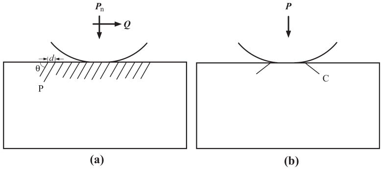
Idealized sphere–flat surface contact models, showing (a) partial cone cracks (P) under a sliding Hertzian contact, and (b) classical cone cracks (C) upon an axial Hertzian contact. Note: Pn and Q denote normal and tangential loads, respectively, in frictional sliding Hertzian contact, while P is the axial load in frictionless normal Hertzian contact. d and θ represent the space between the partial cones, and the angle between the partial cone and specimen surface, respectively.
The current sliding tests were designed to determine the critical normal load Pn for the onset of surface herringbone cracking in the wake of the sliding contact. Tests were run in a biaxial mode: the indenter contacted the specimen surface, the load ramped to the prescribed maximum value, while the specimen holder translated horizontally for 4 mm at a constant velocity v = 2 mm s−1. The range of normal contact load investigated was 5–2000 N; the loading rate was 2000 N s−1. Therefore, depending on the magnitude of the prescribed normal load, it took 2.5 ms to 1 s to reach the prescribed load. Once the prescribed load was attained, the frictional sliding reached a steady state. The normal load Pn and the tangential force Q were monitored continuously using vertical and horizontal load cells. The steady-state coefficient of friction μ was calculated: μ = Q/Pn (Eq. (2)). Each test was performed with a predetermined normal load; at least three tests were conducted on different specimens of each type of material. If no surface cracking was observed, the normal load was increased. The smallest load increment per step was 2 N. Once the cracks were observed, a minimum of six repeats of multiple specimens were performed for the critical load per specimen type. The normal load was then further increased to examine the severity of sliding contact damage.
Frictionless normal load tests were also performed to determine the critical load for the onset of classical ring cracks on the ceramic surface in water, using a same size WC indenter.
3.3. Microscopy and analysis
Scanning electron microscopy (SEM) (Hitachi 3500N, Japan) was used to determine the microstructure of various ceramics. Prior to SEM examination, the polished surfaces of the porcelains and lithium disilicate were etched with 4.9% hydrofluoric acid for 20 s. For alumina and zirconia, the polished sections were thermally etched at 1500 °C and 1300 °C, respectively. The heating and cooling rate was 500 °C h−1; the dwell time was 20 min. For elastically graded ceramics, both surfaces and cross sections (i.e. in the direction perpendicular or parallel to the modulus gradients) were polished. All specimens were coated with a thin layer of carbon to prevent surface charging.
Specimens after each frictional sliding test or frictionless normal indentation were subjected to damage examination using combined optical microscopy (three-dimensional polarized specular reflection microscope, Edge R400, Micro Science Technologies, Marina Del Rey, CA) and SEM. Randomly selected specimens were also sectioned across contact damage, polished and, in some cases, lightly etched for subsurface damage evaluation [33,56].
3.4. Calibration of theoretical models
Based on Hertzian contact stress fields and using the fracture mechanics criterion, contours of critical loads to cause herringbone cracks were calculated for μ varying between 0 and 1 from the constitutive Eq. (8) (a fracture mechanics model) using the properties for target ceramics and the indenter material given in Table 1. They were compared with data predicted from Eq. (4), in conjunction with the experimentally determined critical fracture load P for frictionless normal contact (a semi-empirical model). Finally, data computed using the above models were calibrated with the experimental results.
4. Results and analysis
4.1. Ceramic microstructures
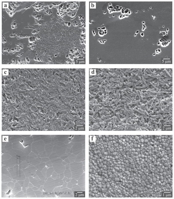
Microstructures of the conventional dental ceramics investigated in this study are shown in Fig. 2. Images were taken using secondary electrons by SEM. The acid-etched surface of d.Sign fluorospathic porcelain in Fig. 2a contained two crystalline phases: the clusters of round, relatively coarse leucite crystallites (<3 μm) and the scattered, needle-like fine fluorapatite crystals (<2 μm in length with aspect ratios, length to width ratio, around 4). Some microcracks were also observed in the glassy matrix and between the leucite crystals and the glass matrix. The LAVA porcelain in Fig. 2b contained smaller clusters of more or less rounded leucite crystals (<4 μm) evenly distributed in a glassy matrix. Very few microcracks were present in the glass, and none between the leucite particles and the glass matrix. The leucite contents in d.Sign and LAVA porcelains were estimated to be 25.0% ± 0.1% and 5.7% ± 0.2%, respectively.
Fig. 2.
Microstructures of conventional dental ceramics investigated in this study. Images were taken using secondary electrons by SEM. Feldspathic overlay porcelains: (a) d.Sign; (b) LAVA. Acid-etched surface revealing craters used to be occupied by leucite crystals and microcracks in the glassy matrix. Lithium disilicate glass–ceramics: (c) CAD and (d) Press. Acid-etched surface revealing elongated lithium disilicate crystallites. Polycrystalline ceramics: (e) alumina and (f) zirconia. Thermally etched surface, revealing a fine, equiaxed microstructure.
Lithium disilicate CAD in Fig. 2c and Press in Fig. 2d both contained ~70% needle-like elongate crystallites. In the Press grade lithium disilicate structure, the crystallites were ~4 μm long and 0.6 μm wide, whereas the crystallites in grade CAD structure were ~2 μm long and 0.4 μm wide.
The strong polycrystalline alumina (Fig. 2e) and zirconia (Fig. 2f) materials exhibited an equiaxed grain morphology; however, the average particle size of zirconia (~0.4 μm) was much smaller than that of alumina (~5 μm).
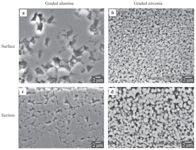
SEM micrographs of the two experimental functionally graded ceramics are shown in Fig. 3. In this case, the dense alumina or zirconia templates were glass infiltrated at 1550 °C or 1450 °C, respectively, for 2 h in air. Fig. 3a and b shows the surface views of graded alumina and zirconia, respectively. In both cases, glass had infiltrated along the grain boundaries of the polycrystalline ceramics. Isolated grain pullouts, resulting from the lapping and polishing procedures, were evident. The cross-sectional views of graded alumina and zirconia are shown in Fig. 3c and d, respectively. The glass content was relatively high at the graded surface, which decreased as the distance from the surface increased. Eventually, the graded glass–ceramic layer gave way to a highly crystalline ceramic core.
Fig. 3.
Microstructures of in-house developed functionally graded ceramics. (a) and (b) SEM secondary electron images of top surface view of graded alumina and zirconia, respectively. (c) and (d) Backscattered electron images of cross-section view of graded alumina and zirconia, respectively.
4.2. Crack morphology
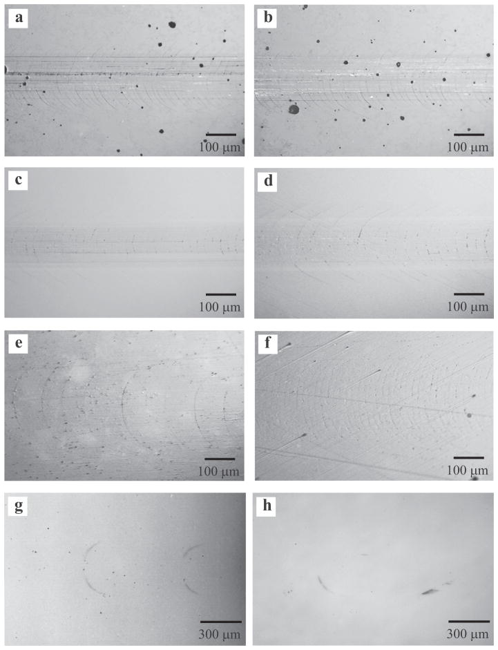
Fig. 4 shows the representative optical micrographs of the emerging herringbone cracks on various ceramic surfaces under loads near critical values. The sliding direction is from left to right in the micrographs. These embryonic herringbone cracks took the form of incomplete ring cracks, which remained predominantly on the ceramic surface and did not extend deep into the material. The ranking of the materials, in descending order of fracture resistance, was the graded zirconia, zirconia, graded alumina, alumina, the two lithium disilicate glass–ceramics and the two types of porcelain materials. It was challenging to introduce surface ring cracks in the graded zirconia; there were no cracks observed even at the maximum capacity of the load cell Pn = 2000 N. The results also showed that elastically graded ceramics, with a low modulus at the surface and higher modulus therein, exhibited much improved resistance to sliding contact fracture relative to their homogeneous counterparts. The critical load for the formation of herringbone cracks was Pn = 250 N and 600 N for monolithic alumina and zirconia, respectively. However, that threshold value had increased to Pn = 600 N and over 2000 N for graded alumina and zirconia, respectively.
Fig. 4.
Optical micrographs showing the formation of herringbone cracks on the surface of various dental ceramics caused by a WC slider of radius 1.5 mm under normal loads near critical values. (a) IPS d.Sign fluorospathic porcelain (Pn = 30 N, μ = 0.27); (b) LAVA Ceram porcelain (Pn = 25 N, μ = 0.24); (c) IPS e.max lithium disilicate CAD (Pn = 50 N, μ = 0.39); (d) IPS e.max lithium disilicate Press (Pn = 50N, μ = 0.45); (e) alumina (Pn = 300 N, μ = 0.10); (f) graded alumina (Pn = 600 N, μ = 0.16); (g) zirconia (Pn = 600 N, μ = 0.08); and (h) graded zirconia (Pn = 2000 N, μ = 0.12). Sliding direction is from left to right in the micrographs.
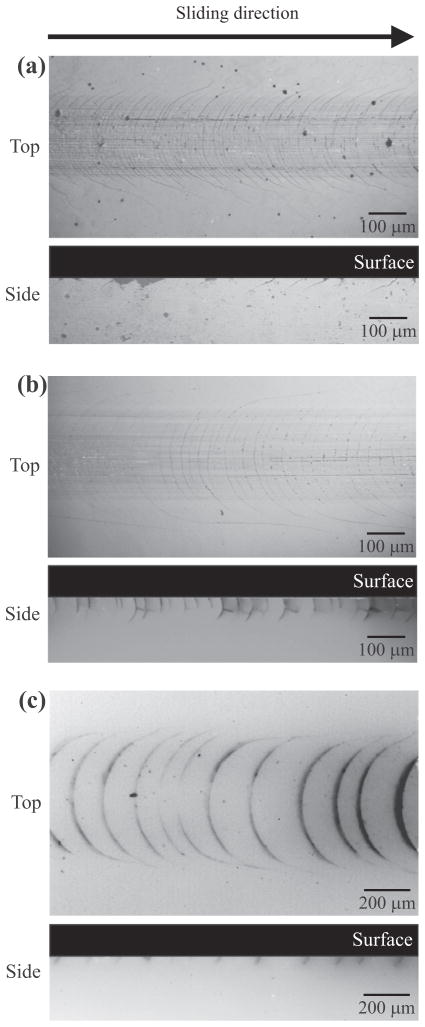
Analogous to Fig. 4, examples of herringbone cracks that formed at loads much higher than critical loads are illustrated in Fig. 5. The surface views demonstrated fairly evenly spaced asymmetrical ring cracks. Fine scratch lines, caused by asperities on the indenter, were also evident along the sliding direction throughout the entire wear track. Sectional views across the contact damage in the direction parallel to the sliding direction revealed subsurface damage: the surface ring cracks had propagated down to form partial cone cracks, where only the crack arm at the trailing edge of the sliding indenter protruded downward. The morphology of the partial cone cracks—such as the density and the angle of the partial cones, characterized by the interval of distance d and crack to surface angle θ, respectively (Fig. 1a)—provides crucial information on the coefficient of friction μ at the interface. A large μ yields both a small d [17,27] and large θ [28,35].
Fig. 5.
Optical micrographs showing surface (top) and side (bottom) views of partial cone cracks in various dental ceramics caused by a WC slider of radius 1.5 mm under specified normal loads: (a) IPS d.Sign fluorospathic porcelain (Pn = 50 N, μ = 0.33); (b) IPS e.max lithium disilicate CAD (Pn = 200 N, μ = 0.25); (c) zirconia (Pn = 1000 N, μ = 0.08).
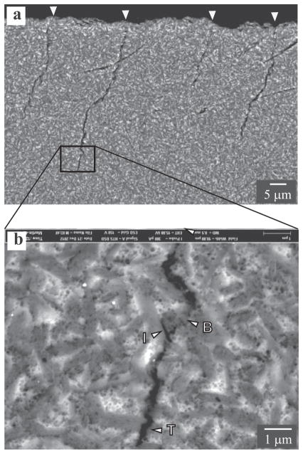
The pertinent features of the subsurface sliding contact patterns in lithium disilicate Press materials are presented in the cross-sectional SEM micrographs in Fig. 6. At relatively low magnifications, it is evident that evenly spaced partial cone cracks have propagated down from the sliding-contact surface at a similar angle of inclination to each other (highlighted by arrows in Fig. 6a). At higher magnification, the SEM view of the crack tip (Fig. 6b) revealed crack bridging (marked by B), intergranular fracture (crack deflection, marked by I, typically for cracks intersected with the grain at an acute angle) and transgranular fracture (marked by T, often for high incidence angles). This and other evidence suggests that lithium disilicate Press glass–ceramics with a coarse, elongated grain morphology exhibit rising toughness, termed R-curve or T-curve behavior, where fracture toughness increases with crack extension due to crack deflection and bridging by interlocked grains [57–59].
Fig. 6.
SEM micrographs revealing section views of partial cone morphology and crack–microstructure interaction in lithium disilicate Press subjected to sliding test using a WC sphere of radius 1.5 mm under normal load Pn = 209 N and μ = 0.29. Various fracture mechanisms are highlighted in (b): crack bridging (marked B), intergranular fracture (marked I) and transgranular fracture (marked T). Sliding direction is from left to right in the micrographs.
4.3. Fracture and friction
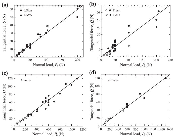
The data for frictional sliding are first examined, without imposing any model-based ideas on them. To do this, the sliding contact data for test materials is plotted on axes of tangential force and normal load in Fig. 7. Solid symbols represent samples that fractured from the sliding contact, while open symbols denote samples that endured sliding tests without any visible cracks. The critical fracture load was ~2000 N for graded zirconia, 600 N for zirconia, 600 N for graded alumina, 250 N for alumina, 25 N for lithium disilicate Press, 20 N for lithium disilicate CAD, 7.5 N for d.Sign porcelain and 5 N for LAVA overlay. Most data points (excepted for the two lithium disilicate materials) can be fitted reasonably well to a family of straight lines that pass through the origin, which can be described by a linear function Q = μPn. The slope of the linear function μ signified the coefficient of friction for each class of materials, being 0.3, 0.3, 0.1 and 0.1 for porcelain, lithium disilicate, alumina and zirconia, respectively.
Fig. 7.
Experimental sliding contact data plotted on axes of tangential force Q and normal load Pn for various dental ceramics: (a) the two porcelains; (b) the two lithium disilicate glass–ceramics; (c) alumina; (d) zirconia. Solid symbols represent samples that fractured from the sliding contact, while open symbols denote samples that endured sliding tests without any visible cracks. The slope of the solid lines implies the coefficient of friction μ (=Q/Pn) for each class of material.
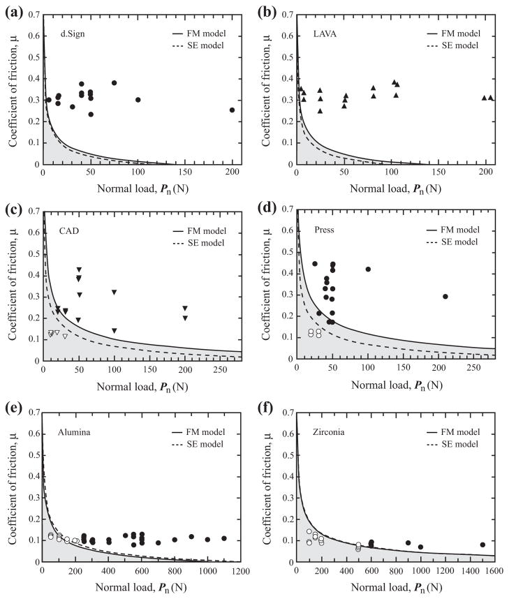
Fig. 8 shows contours of critical loads for the onset of herringbone cracks in each material, calculated from Eq. (8) using the data in Table 1 (a fracture mechanics model), and plotted as solid lines on axes μ and Pn. Shaded areas below the solid curves represent fracture-free operating conditions, while the unshaded regions above the curves are the fracture-dominant areas. Analogous to the solid curves, the dashed lines are the predicted critical loads for the initiation of herringbone cracks from Eq. (4), based on stress analysis and experimentally derived critical fracture loads under frictionless axial loading given in Table 1 (a semi-empirical model). The agreement between the fracture mechanics model and the semi-empirical model is best for alumina and zirconia, worse for the two porcelains (d.Sign and LAVA), and the worst for the two lithium disilicate materials (CAD and Press). To validate these models, experimental data from Fig. 7 are plotted on the μ and Pn axes in Fig. 8. Friction coefficient μ was calculated from the Q and Pn data pair recorded from each sliding test. Open symbols stand for specimens that have endured sliding test without fracture, while the solid symbols represent the fractured ones. Both models agree reasonably well with the experimental data; no adjustable parameters and special correction are needed to fit the experimental data. It is also interesting that μ varies from 0.1 to 0.5 for the two lithium disilicate materials, and from 0.2 to 0.4 for the two porcelains, but has a much narrower distribution for alumina and zirconia—hovering around 0.1 in both cases.
Fig. 8.
Contours of critical loads for the onset of herringbone cracks in each material plotted on axes μ and Pn. Solid curves are fracture load predictions by the fracture mechanics (FM) model, while dashed lines are obtained using the semi-empirical (SE) model. The intersection of each curve and x-axis represents the critical load for frictionless contact (μ = 0). The shaded area below each curve indicates the fracture-free regime. Experimental data from Fig. 7 are also included for comparison. Open symbols stand for specimens that have endured sliding test without fracture, while the solid symbols denote the fractured ones.
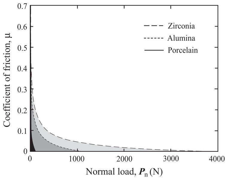
Damage maps for zirconia, alumina and porcelain, plotted on the usual axes μ and Pn, are presented in Fig. 9. The boundary between fractured and unfractured regions was predicted from the constitutive Eq. (8) for each material. The shaded area below each curve signifies a fracture-free safe operating region. To facilitate visual comparison, shaded areas for different materials have been toned into various degrees of gray: zirconia (light), alumina (intermediate) and porcelain (dark). It is apparent that the unfractured region is much larger for zirconia than for alumina, and even more so than porcelain. For each material, two distinct segments are evident: the μ insensitive section at large μ (>0.2), and the μ dominant sector for smaller μ (<0.2).
Fig. 9.
Damage maps for zirconia, alumina and porcelain, predicted from the fracture mechanics model. The shaded area below each curve represents the fracture-free region.
5. Discussion
When a blunt indenter slides over a brittle surface under the action of normal and tangential loads, an array of periodic herringbone cracks form in the wake of the slider. The resistance to this herringbone fracture varies immensely among various dental ceramics: monolithic zirconia is almost 2.5 times more fracture resistant than alumina, and at least 25 times higher than the two lithium disilicate glass–ceramics and, more significantly, over 80 times higher than the two porcelain materials. Additionally, by infiltration of glass compositions into the exposed surfaces of alumina and zirconia, the fracture resistance can be further increased by a factor of 2.5 and 3, respectively. This is because such infiltration produces an elastic gradient at the ceramic surface, where the low-modulus glass–ceramic effectively reduces the contact stress and transfers the maximum tensile stress into the high-modulus ceramic interior, circumventing the formation of herringbone cracks.
The initiation of herringbone cracks can be predicted from a simple constitutive equation (Eq. (8)), which conveniently incorporates the critical fracture load Pn with the interfacial friction coefficient and the ceramic properties, most notably fracture toughness. The estimated critical fracture loads for various dental ceramics are in fairly good agreement with data predicted from a semi-empirical model. The predicted fracture-boundary contours using the above models show broad agreement with the experimental data points.
The dependence of critical load on the magnitude of the interfacial friction coefficient warrants further discussion. Stress analysis based on theory of elasticity clearly demonstrates that the friction intensifies the tensile stress at the trailing edge of a moving indenter (Eq. (3)), which, in turn, can significantly reduce the critical load for fracture (Eq. (4)) [16,19,41]. What has not been established before is that the dependence of critical load on the coefficient of friction can be divided into two different domains: a μ dominant regime at small μ (<0.2) and a μ insensitive region for a larger μ (>0.2) (Figs. 8 and 9). Under the current experimental conditions, i.e. using a rigid WC indenter of radius r = 1.5 mm, theory predicts that, for μ = 0.1, critical fracture loads are 23 N, 149 N and 323 N for porcelain, alumina and zirconia, respectively. As the friction coefficient diminishes, say μ = 0.05 for instance, critical loads are rapidly increased to 49 N (porcelain), 340 N (alumina) and 862 N (zirconia). However, at a larger μ = 0.3, critical loads are abruptly diminished in all material, being 3 N, 20 N and 34 N for porcelain, alumina and zirconia, respectively. Nevertheless, the high toughness and strength of zirconia clearly exhibit the ability to withstand a higher load than alumina and porcelain. Zirconia outperforms alumina by a factor of 1.6 (at μ = 0.5) to 2.5 (at μ = 0.05) and porcelain by an order of magnitude or more.
The predicted material dependence of the fracture condition merits further attention. Theory suggests that ceramics with a large fracture toughness and small elastic modulus are particularly well suited for resisting sliding contact fracture. This explains why zirconia exhibits superior resistance to sliding contact fracture relative to alumina; the former possesses a higher toughness and lower modulus. Similarly, lithium disilicate glass–ceramics are superior to porcelains because of their higher fracture toughness and comparable modulus of elasticity to porcelain. However, detailed examination has revealed that the constitutive equation works perfectly for ceramics with a homogeneous fine grain microstructure, such as alumina and zirconia. For crystal-reinforced porcelains and glass–ceramics, better agreement has been observed between the critical loads predicted from the fracture mechanics and the semi-empirical models in porcelains than lithium disilicate glass–ceramics. This is because fracture toughness of fine-grained ceramics has a near-constant value [60], whereas that of particle reinforced porcelains and glass–ceramics often exhibits R-curve behavior [61,62]. The mechanisms responsible for this crack-sizedependent toughness have been unequivocally established as grain-localized crack deflection and crack bridging [59,63]. Lithium disilicate glass–ceramics consist of interlocking reinforcement rods, which effectively promote crack deflection and bridging. Such a microstructure is much more effective to evoke an R-curve than that of porcelains, in which the reinforcement particles are predominantly equiaxed leucite crystals [62]. The fracture toughness of these materials, measured in traditional fracture mechanics tests, is the steady state or long-crack fracture toughness, which is higher than the toughness that encounters the initiation of herringbone cracks in the short crack region. Thus, Eq. (8), using longcrack toughness, tends to overestimate the resistance to sliding contact of leucite reinforced porcelains, and more significantly, lithium disilicate glass–ceramics.
The design philosophy for ceramic dental and biomechanical prostheses is to keep them operating in a mild wear region. The minimum criterion to satisfy this requirement is to prevent sliding contact fracture. The key to this is to keep the coefficient of friction low (μ < 0.2). While a high-toughness material offers much better resistance to sliding contact fracture, if the friction at the interface of two contacting bodies is high, such advantage can quickly diminish. Such dangerously high friction can be easily reached in materials with coarse grain and/or elongated grain morphology. In this sense, fine-grain, high-toughness zirconia clearly has the advantage over other dental ceramics. Remarkably, by infiltrating glass into the surface of zirconia, its resistance to sliding contact fracture can be further improved by a factor of 3 or more. Such an elastically graded material offers great potential for applications where resistance to sliding contact fracture is paramount.
The present authors acknowledge that, as with the Auerbach behavior under frictionless normal load, the fracture initiation threshold load varies linearly with the indenter radius at small radii (r ≤ 10 mm) [64]. In frictional sliding, the current Eqs. (4) and (8) are valid for small radii (r < 5 mm) and moderately low coefficient of friction (μ < 0.5). These criteria are, however, easily met in dental occlusion, where the radius of the antagonistic cusp is typically a couple of millimeters in size [65], and the coefficient of friction for dental ceramics is usually <0.5 (Fig. 8).
6. Conclusion
It seems reasonable to develop a fracture mechanics based constitutive equation (Eq. (8)) to describe the onset of herringbone cracks in ceramics in the presence of a tangential force. The critical fracture load depends on the contact geometry, the interfacial friction coefficient and material properties, especially fracture toughness. A large contact curvature, a small friction coefficient and high fracture toughness can all suppress the formation of sliding contact fracture in ceramics. Fine-grained, high-strength ceramics exhibit better resistance to sliding contact damage than coarse-grained glass–ceramics and porcelains do. The sliding contact resistance of fine-grained, high-strength ceramics can be further improved by surface glass infiltration.
Acknowledgments
This investigation was supported by Research Grant R01 DE017925 (P.I. Zhang) from the United States National Institute of Dental and Craniofacial Research, National Institutes of Health and Research Grant CMMI-0758530 (P.I. Zhang) from the United States Division of Civil, Mechanical and Manufacturing Innovation, National Science Foundation.
Footnotes
Disclosure
All authors declare no conflict of interest.
References
- 1.Hsu SM, Shen MC. Ceramic wear maps. Wear. 1996;200:154–75. [Google Scholar]
- 2.Barrack RL, Burak C, Skinner HB. Concerns about ceramics in THA. Clin Orthop Relat Res. 2004;429:73–9. doi: 10.1097/01.blo.0000150132.11142.d2. [DOI] [PubMed] [Google Scholar]
- 3.Jarrett CA, Ranawat AS, Bruzzone M, Blum YC, Rodriguez JA, Ranawat CS. The squeaking hip: a phenomenon of ceramic-on-ceramic total hip arthroplasty. J Bone Joint Surg. 2009;91:1344–9. doi: 10.2106/JBJS.F.00970. [DOI] [PubMed] [Google Scholar]
- 4.Jazrawi LM, Kummer FJ, Di Cesare PE. Hard bearing surfaces in total hip arthroplasty. Am J Orthop (Belle Mead, NJ) 1998;27:283–92. [PubMed] [Google Scholar]
- 5.Mehmood S, Jinnah RH, Pandit H. Review on ceramic-on-ceramic total hip arthroplasty. J Surg Orthop Adv. 2008;17:45–50. [PubMed] [Google Scholar]
- 6.Willmann G. Ceramics for total hip replacement – what a surgeon should know. Orthopedics. 1998;21:173–7. doi: 10.3928/0147-7447-19980201-11. [DOI] [PubMed] [Google Scholar]
- 7.Kern M, Sasse M, Wolfart S. Ten-year outcome of three-unit fixed dental prostheses made from monolithic lithium disilicate ceramic. J Am Dent Assoc. 2012;143:234–40. doi: 10.14219/jada.archive.2012.0147. [DOI] [PubMed] [Google Scholar]
- 8.Oden A, Andersson M, Krystek-Ondracek I, Magnusson D. Five-year clinical evaluation of Procera AllCeram crowns. J Prosthet Dent. 1998;80:450–6. doi: 10.1016/s0022-3913(98)70010-1. [DOI] [PubMed] [Google Scholar]
- 9.Pjetursson BE, Sailer I, Zwahlen M, Hämmerle CHF. A systematic review of the survival and complication rates of all-ceramic and metal–ceramic reconstructions after an observation period of at least 3 years. Part I: single crowns. Clin Oral Implants Res. 2007;18:73–85. doi: 10.1111/j.1600-0501.2007.01467.x. [DOI] [PubMed] [Google Scholar]
- 10.Sailer I, Pjetursson BE, Zwahlen M, Hammerle CH. A systematic review of the survival and complication rates of all-ceramic and metal–ceramic reconstructions after an observation period of at least 3 years. Part II: fixed dental prostheses. Clin Oral Implants Res. 2007;18(Suppl 3):86–96. doi: 10.1111/j.1600-0501.2007.01468.x. [DOI] [PubMed] [Google Scholar]
- 11.Sax C, Hammerle CH, Sailer I. 10-year clinical outcomes of fixed dental prostheses with zirconia frameworks. Int J Comput Dent. 2011;14:183–202. [PubMed] [Google Scholar]
- 12.Hertz H. On the contact of elastic solids. J Reine und Angewandte Mathematik. 1882;92:156–71. [Google Scholar]
- 13.Huber MT. On the theory of the contact of solid elastic substances. Annalen Der Physik. 1904;14:153–63. [Google Scholar]
- 14.Mindlin RD. Force at a point in the interior of a semi-infinite solid. Phys-a J Gen Appl Phys. 1936;7:195–202. [Google Scholar]
- 15.Mindlin RD. Compliance of elastic bodies in contact. J Appl Mech-Trans ASME. 1949;16:259–68. [Google Scholar]
- 16.Hamilton GM, Goodman LE. The stress field created by a circular sliding contact. J Appl Mech. 1966;33:371–6. [Google Scholar]
- 17.Lawn BR. Partial cone crack formation in a brittle material loaded with a sliding indenter. Proc R Soc London. 1967;A299:307–16. [Google Scholar]
- 18.Johnson KL. Contect mechanics. Cambridge: Cambridge University Press; 1985. [Google Scholar]
- 19.Hamilton GM. Explicit equations for the stresses beneath a sliding spherical contact. Proc Inst Mech Eng. 1983;197C:53–9. [Google Scholar]
- 20.Gilroy D, Hirst W. Brittle fracture of glass under normal and sliding loads. J Phys D: Appl Phys. 1969;2:1784–7. [Google Scholar]
- 21.Woda A, Vigneron P, Kay D. Nonfunctional and functional occlusal contacts: a review of the literature. J Prosthet Dent. 1979;42:335–41. doi: 10.1016/0022-3913(79)90226-9. [DOI] [PubMed] [Google Scholar]
- 22.DeLong R, Douglas WH. Development of an artificial oral environment for the testing of dental restoratives: bi-axial force and movement control. J Dent Res. 1983;62:32–6. doi: 10.1177/00220345830620010801. [DOI] [PubMed] [Google Scholar]
- 23.Kim JH, Kim JW, Myoung SW, Pines M, Zhang Y. Damage maps for layered ceramics under simulated mastication. J Dent Res. 2008;87:671–5. doi: 10.1177/154405910808700706. [DOI] [PMC free article] [PubMed] [Google Scholar]
- 24.Kim JW, Kim JH, Janal MN, Zhang Y. Damage maps of veneered zirconia under simulated mastication. J Dent Res. 2008;87:1127–32. doi: 10.1177/154405910808701210. [DOI] [PMC free article] [PubMed] [Google Scholar]
- 25.Chiang SS, Evans AG. Influence of a tangential force on the fracture of 2 contacting elastic bodies. J Am Ceram Soc. 1983;66:4–10. [Google Scholar]
- 26.Bower AF, Fleck NA. Brittle-fracture under a sliding line contact. J Mech Phys Solids. 1994;42:1375–96. [Google Scholar]
- 27.Keer LM, Kuo CH. Cracking in a loaded, brittle elastic half-space. Int J Solids Struct. 1992;29:1819–26. [Google Scholar]
- 28.Keer LM, Worden RE. A qualitative model to describe the microchipping wear mode in ceramic rollers. Tribol Trans. 1990;33:411–7. [Google Scholar]
- 29.Shah KR, Wong TF. Fracturing at contact surfaces subjected to normal and tangential loads. Int J Rock Mech Min Sci. 1997;34:727–39. [Google Scholar]
- 30.Kuo CH, Keer LM. Contact stress-analysis of a layered transversely isotropic half-space. J Tribol-Trans ASME. 1992;114:253–62. [Google Scholar]
- 31.Rhee Y-W, Kim H-W, Deng Y, Lawn BR. Brittle fracture versus quasiplasticity in ceramics: a simple predictive index. J Am Ceram Soc. 2001;84:561–5. [Google Scholar]
- 32.Bethune B. Surface cracking of glassy polymers under a sliding spherical indenter. J Mater Sci. 1976;11:199–205. [Google Scholar]
- 33.Kim JW, Kim JH, Thompson VP, Zhang Y. Sliding contact fatigue damage in layered ceramic structures. J Dent Res. 2007;86:1046–50. doi: 10.1177/154405910708601105. [DOI] [PMC free article] [PubMed] [Google Scholar]
- 34.Kim JW, Liu L, Zhang Y. Improving the resistance to sliding contact damage of zirconia using elastic gradients. J Biomed Mater Res Part B. 2010;94:347–52. doi: 10.1002/jbm.b.31657. [DOI] [PMC free article] [PubMed] [Google Scholar]
- 35.Lawn BR, Wiederhorn SM, Roberts DE. Effect of sliding friction forces on the strength of brittle materials. J Mater Sci. 1984;19:2561–9. [Google Scholar]
- 36.Suresh S, Olsson M, Giannakopoulos AE, Padture NP, Jitcharoen J. Engineering the resistance to sliding-contact damage through controlled gradients in elastic properties at contact surfaces. Acta Mater. 1999;47:3915–26. [Google Scholar]
- 37.Zhang Y, Kim JW, Kim JH, Lawn BR. Fatigue damage in ceramic coatings from cyclic contact loading with a tangential component. J Am Ceram Soc. 2008;91:198–202. [Google Scholar]
- 38.Lawn BR. Indentation of ceramics with spheres: a century after Hertz. J Am Ceram Soc. 1998;81:1977–94. [Google Scholar]
- 39.Amontons G. De la resistance causée dans les machines. Mem de l’Academie Royale A. 1699:275–82. [Google Scholar]
- 40.Green AE. On Boussinesq’s problem and penny-shaped cracks. Math Proc Cambridge Philos Soc. 1949;45:251–7. [Google Scholar]
- 41.Sackfield A, Hills DA. Some useful results in the tangentially loaded Hertzian contact problem. J Strain Anal Eng Des. 1983;18:107–10. [Google Scholar]
- 42.Frank FC, Lawn BR. On the theory of Hertzian fracture. Proc R Soc London. 1967;A299:291–306. [Google Scholar]
- 43.Kato K, Adachi K. Wear of advanced ceramics. Wear. 2002;253:1097–104. [Google Scholar]
- 44.Rainforth WM. The wear behaviour of oxide ceramics – a review. J Mater Sci. 2004;39:6705–21. [Google Scholar]
- 45.Holand W, Kappert H, Peschke A, Schweiger M, Watzke R. Ceramics as biomaterials for dental restoration. Expert Rev Med Devices. 2008;5:729–45. doi: 10.1586/17434440.5.6.729. [DOI] [PubMed] [Google Scholar]
- 46.Zhang Y, Lee JJ, Srikanth R, Lawn BR. Edge chipping and flexural resistance of monolithic ceramics. Dent Mater. 2013;29:1201–8. doi: 10.1016/j.dental.2013.09.004. [DOI] [PMC free article] [PubMed] [Google Scholar]
- 47.Ren L, Liu L, Bhowmick S, Gerbig YB, Janal MN, Thompson VP, et al. Improving fatigue damage resistance of alumina through surface grading. J Dent Res. 2011;90:1026–30. doi: 10.1177/0022034511408427. [DOI] [PMC free article] [PubMed] [Google Scholar]
- 48.Ren L, Janal MN, Zhang Y. Sliding contact fatigue of graded zirconia with external esthetic glass. J Dent Res. 2011;90:1116–21. doi: 10.1177/0022034511412075. [DOI] [PMC free article] [PubMed] [Google Scholar]
- 49.Zhang Y, Kim JW. Graded structures for damage resistant and aesthetic all-ceramic restorations. Dent Mater. 2009;25:781–90. doi: 10.1016/j.dental.2009.01.002. [DOI] [PMC free article] [PubMed] [Google Scholar]
- 50.Zhang Y. Overview: damage resistance of graded ceramic restorative materials. J Eur Ceram Soc. 2012;32:2623–32. doi: 10.1016/j.jeurceramsoc.2012.02.020. [DOI] [PMC free article] [PubMed] [Google Scholar]
- 51.Zhang Y, Chai H, Lawn BR. Graded structures for all-ceramic restorations. J Dent Res. 2010;89:417–21. doi: 10.1177/0022034510363245. [DOI] [PMC free article] [PubMed] [Google Scholar]
- 52.Zhang Y, Chai H, Lee JJ, Lawn BR. Chipping resistance of graded zirconia ceramics for dental crowns. J Dent Res. 2012;91:311–5. doi: 10.1177/0022034511434356. [DOI] [PMC free article] [PubMed] [Google Scholar]
- 53.Zhang Y, Sun MJ, Zhang D. Designing functionally graded materials with superior load-bearing properties. Acta Biomater. 2012;8:1101–8. doi: 10.1016/j.actbio.2011.11.033. [DOI] [PMC free article] [PubMed] [Google Scholar]
- 54.Dorthé E, Zhang Y. Load-bearing increase in alumina evoked by introduction of a functional glass gradient. J Eur Ceram Soc. 2012;32:1213–20. doi: 10.1016/j.jeurceramsoc.2011.11.041. [DOI] [PMC free article] [PubMed] [Google Scholar]
- 55.Zhang Y, Ma L. Optimization of ceramic strength using elastic gradients. Acta Mater. 2009;57:2721–9. doi: 10.1016/j.actamat.2009.02.037. [DOI] [PMC free article] [PubMed] [Google Scholar]
- 56.Kim B, Zhang Y, Pines M, Thompson VP. Fracture of porcelain-veneered structures in fatigue. J Dent Res. 2007;86:142–6. doi: 10.1177/154405910708600207. [DOI] [PubMed] [Google Scholar]
- 57.Apel E, Deubener J, Bernard A, Holand M, Muller R, Kappert H, et al. Phenomena and mechanisms of crack propagation in glass–ceramics. J Mech Behav Biomed Mater. 2008;1:313–25. doi: 10.1016/j.jmbbm.2007.11.005. [DOI] [PubMed] [Google Scholar]
- 58.Guazzato M, Albakry M, Ringer SP, Swain MV. Strength, fracture toughness and microstructure of a selection of all-ceramic materials. Part I. Pressable and alumina glass-infiltrated ceramics. Dent Mater. 2004;20:441–8. doi: 10.1016/j.dental.2003.05.003. [DOI] [PubMed] [Google Scholar]
- 59.Li CW, Lui SC, Goldacker J. Relation between strength, microstructure, and grain-bridging characteristics in in-situ reinforced silicon-nitride. J Am Ceram Soc. 1995;78:449–59. [Google Scholar]
- 60.Chantikul P, Bennison SJ, Lawn BR. Role of grain size in the strength and R-curve properties of alumina. J Am Ceram Soc. 1990;73:2419–27. [Google Scholar]
- 61.Cesar PF, Rosa V, Pinto MM, Yoshimura HN, Xu LR. Effect of ion exchange on Rcurve behavior of a dental porcelain. J Mater Sci. 2011;46:117–22. [Google Scholar]
- 62.Fischer H, Rentzsch W, Marx R. R-curve behavior of dental ceramic materials. J Dent Res. 2002;81:547–51. doi: 10.1177/154405910208100809. [DOI] [PubMed] [Google Scholar]
- 63.Lawn BR. Fracture of brittle solids. 2. Cambridge: Cambridge University Press; 1993. [Google Scholar]
- 64.Tillett JP. Fracture of glass by spherical indenters. Proc Phys Soc London. 1956;B69:47–54. [Google Scholar]
- 65.Krejci I, Albert P, Lutz F. The influence of antagonist standardization on wear. J Dent Res. 1999;78:713–9. doi: 10.1177/00220345990780021201. [DOI] [PubMed] [Google Scholar]


