Abstract
Background
Rodents are important model systems used to explore Spinal Cord Injury (SCI) and rehabilitation, and Brain Machine Interfaces. We present a new method to provide mechanical interaction for BMI and rehabilitation in rat models of SCI.
New Method
We present the design and implantation procedures for a pelvic orthosis that allows direct force application to the skeleton in brain machine interface and robot rehabilitation applications in rodents. We detail the materials, construction, machining, surgery and validation of the device.
Results
We describe the statistical validation of the implant procedures by comparing stepping parameters of 8 rats prior to and after implantation and surgical recovery. An ANOVA showed no effects of the implantation on stepping. Paired tests in the individual rats also showed no effect in 7/8 rats and minor effects in the last rat, within the group's variance.
Comparison with Existing Methods
Our method allows interaction with rats at the pelvis without any perturbation of normal stepping in the intact rat. The method bypasses slings, and cuffs, avoiding cuff or slings squeezing the abdomen, or other altered sensory feedback. Our implant osseointegrates, and thus allows an efficient high bandwidth mechanical coupling to a robot. The implants support quadrupedal training and are readily integrated into either treadmill or overground contexts.
Conclusions
Our novel device and procedures support a range of novel experimental designs and motor tests for rehabilitative and augmentation devices in intact and SCI model rats, with the advantage of allowing direct force application at the pelvic bones.
Keywords: Brain Machine Interface, Neurorobotics, Robot rehabilitation, Locomotion, Biomechanic Perturbations
1. Introduction
As part of a system to allow novel robotic-rehabilitation in rats(Udoekwere et al., 2006) and Brain Machine Interface experiments ((Song and Giszter, 2011), (Song et al., 2009)) we have developed a pelvic implantation surgical technique and apparatus that allows direct application of robot generated forces and torques in the pelvic bones. This paper describes the techniques of construction, implantation and validation needed to replicate our methods in other laboratories. The value of our techniques are that they allow sensorimotor impedance training that targets the mid-low trunk muscles in spinalized rats, and perturbation or interaction in intact rats. Further, the techniques we have developed might also be generalized to smaller animals such as mice with similar materials, or larger animals such as cats using titanium parts.
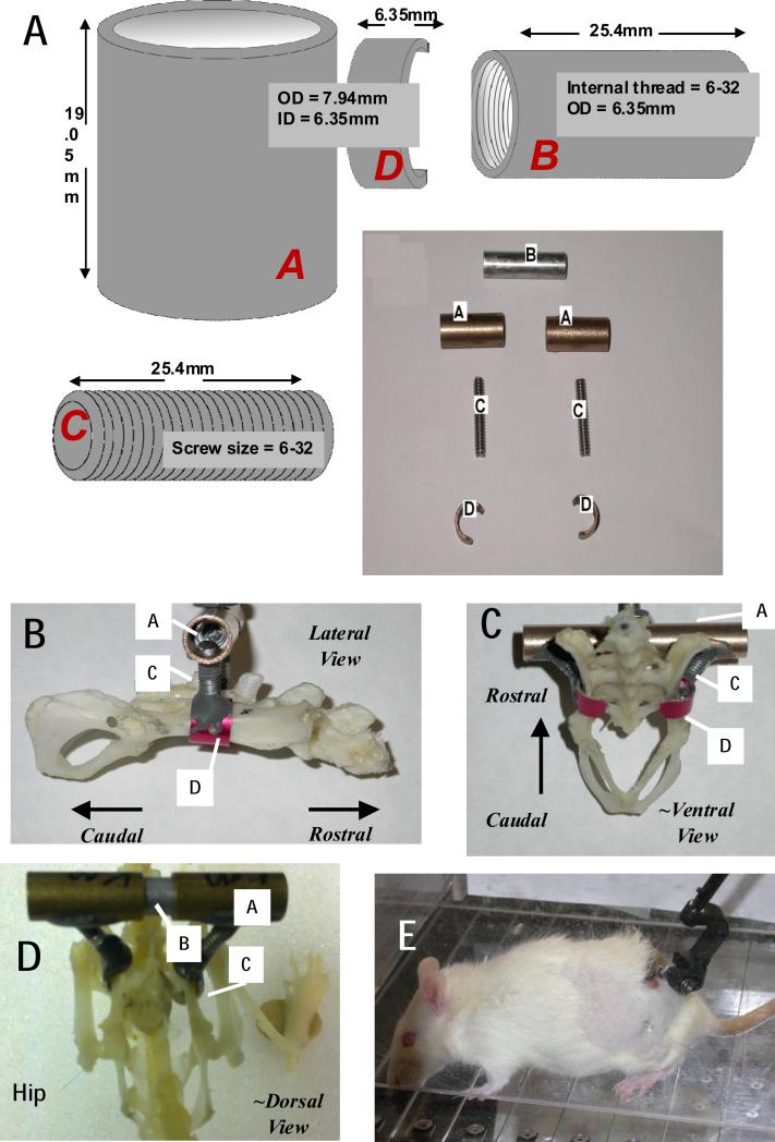
We describe a pelvic orthosis that clamps to the animals pelvic girdle (as shown in Figure 1) and extends to a conduit outside the animal's body for force application. Typically, in our hands this occurs through the (active or passive) gimbal of a haptic robotic arm which is attached using standard hardware (e.g., Figure 1E). The robotic arm allows us to generate and apply elastic forces around the pelvis and mid/low trunk region while the animal walks on a treadmill quadrupedally. In principle 6 degree of freedom interaction is feasible. We have currently successfully implanted over 80 rats. The aim of this paper is to describe the pelvic orthosis design, surgical implantation technique and the associated concerns. We also discuss means we have used for validation of the minimal effects of the orthotic and surgical implantation on the intact animal's locomotion by assessing the kinematics of locomotion prior to and after implantation, and present these data.
Figure 1. Components and dimensions for pelvic orthosis fabrication, and skeletal placement.
A. Components. Component labels are in italics. A female threaded aluminum standoff (B), a pair of stainless steel screw rods(C), bronze sleeve bearings(A), and aluminum cuffs or c-clamps (D) having an arc of ~190-210 degrees, were used to fabricate the pelvic orthosis. A/C/D are assembled and cemented prior to sterilization for surgery. After insertion, and tightening of implant placement in surgery , A and B are secured to one another with epoxy steel adhesive. B. Lateral View with assembled components labeled. C ~Ventral View, with assembled components labeled. D. ~ Dorsal view on Full rat skeleton with hip/leg visible and components labeled. E Completed implanted assembly in awake rat with a phantom 1.0 robot attached to the A/B assembly.
2. Materials and Methods
All experiments and processes described here were developed and implemented with approval and full oversight from Drexel University IACUC and ULAR in accordance with PHS and USDA regulations and guidelines.
We first discuss hardware design and construction features, and then implantation procedures and assessment methods.
2.1 Pelvic Orthosis/Implant Design
A female threaded aluminum standoff, a pair of stainless steel screw rods, bronze sleeve bearings, and aluminum sleeves (McMaster-Carr) were used to fabricate the pelvic orthosis as shown in Figure 1 A. The complete design, including dimensions, is shown in Figure 1. Each bronze sleeve is drilled and then tapped at a 60° angle. This enables each screw rod to screw in at an angle of 60° to each bronze sleeve. The screw rod is screwed in enough to ensure a tight fit but should not protrude into the hollow part of the sleeve. This is necessary to allow the aluminum standoff fit easily into the hollow bronze sleeves for tight clamping after surgical implantation of the completed orthosis (this is explained further in Surgical Concerns section). About a 1mm protrusion of the rod into sleeve's conduit is acceptable. The joint made between the bronze sleeve and the screw rod is referred to as the sleeve-screw joint. The sleeve-screw joint is then further reinforced with JB weld epoxy steel. The aluminum sleeves are then drilled and tapped at 90°. The free end of the screw rod, of which the other end has already been attached to the bronze sleeve, is screwed into the aluminum sleeves. The aluminum sleeves are then cut to make the cuff or C-clamp as shown in Figure 1. These represent 190-210 degrees of arc, i.e. 150-170 degrees of arc are cut out. The edges of the C are smoothed and beveled. If drilled and tapped appropriately, the screw rod should screw tightly without any protrusion into the concave aspect of the cuff. Protrusions are likely to irritate the iliac bone when the cuff clamps the pelvis after implantation. This joint is referred to as the cuff-screw joint and is also reinforced with JB Weld. The curved end of the cuff furthest from the cuff-screw joint is then filed down to avoid an ‘overhook’ curvature (potentially irritating and inflaming nerve or muscle). The cut edges of the cuff closest are beveled and filed smooth. These final cuff adjustments are necessary to avoid impinging the sciatic nerve and irritating surrounding gluteus muscles respectively (explained further in surgical concern section). The weight of the combined finished orthosis is approximately 10g. We have also successfully fabricated a lighter (~ 5g) orthosis by replacing the bronze sleeve bearings and aluminum standoffs with equivalent plastic parts. The stiffness of materials in relation to animal forces are the crucial feature in these substitutions. Sufficient orthosis rigidity to allow osseointegration and stable force transmission to the pelvis is key, and material stiffness, durability and weight constrain these designs. The surgical kit orthosis components then consists of one or more sets of the two C-clamp/rod/sleeve assemblies and the central stand-off. These are autoclaved in the standard fashion in a standard autoclave bag : all quoted materials can easily withstand well beyond autoclave heat temperatures.
2.2 Surgical Implantation
All experimental surgical and subsequent procedures complied fully with the guidelines of the National Institute of Health Guide for the Care and Use of Laboratory Animals and received IACUC approval. Adult female Sprague–Dawley rats (275–320 g) were anesthetized intraperitoneally with 1.0ml/kg KXA (2.0ml Ketamine (100 mg/kg), 1.0ml Xylazine (20 mg/kg), 0.15ml Acepromazine (10 mg/kg)). Supplemental doses of KXA were administered intraperitoneally (IP) as needed to maintain a deep level of anesthesia during the procedure. All surgical procedures were performed under aseptic conditions.
Implantation procedures used in this study are as follows:
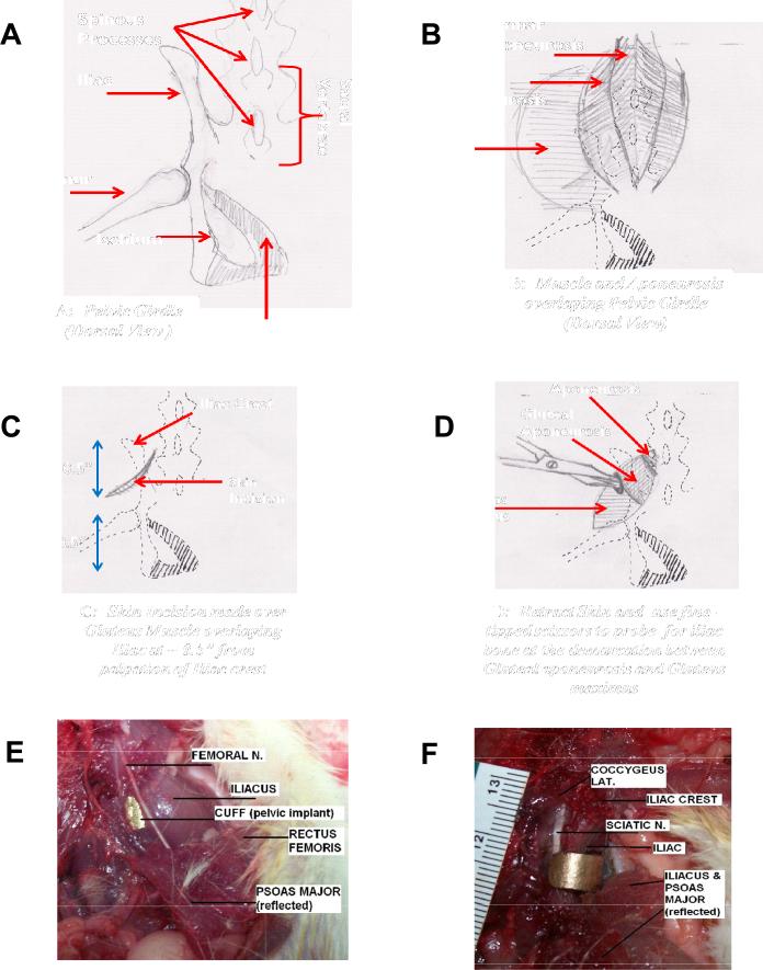
The iliac crest on the pelvis is identified by palpation, and an angled skin incision approximately half and inch caudal to the iliac crest is made (Figure 2C). The skin around the incision is loosened and separated from the muscle by blunt dissection to reveal the gluteal aponeurosis just bordering the lumbar aponeurosis (Figure 2B&D). The border between the gluteus maximus and the gluteal aponeurosis (i.e. sheet-like tendon striations seen at medial/proximal end of gluteus maximus muscle) is identified (Figure 2B). This aponeurosis border is probed gently with fine-tipped scissors (Tiemann 105-576) at approximately half an inch caudal to the iliac crest to feel the iliac process beneath (Figure 2D). Using the fine-tipped scissors at the same location, this aponeurosis border is carefully probed and simultaneously blunt dissected to create a small opening towards the iliac process beneath (Figure 2D). For easy separation and minimal blunt dissecting effort, probing should be done along the line of this aponeurosis border (Figure 2B&D). The tip of the scissors should not descend more than 5mm-7mm during this process to prevent lesioning or bruising the psoas major muscle, iliacus muscle and femoral nerve on the ventral side of the pelvic girdle (Figure 2 E and F). Once the tip of the scissors reaches the iliac process beneath the gluteus muscles, care should be taken to blunt dissect and free the the gluteus maximus as well as deeper gluteus muscles (gluteus medius and minimus) from the dorso-lateral surface of the iliac process and sacral spine,. All this is done within the vicinity of the probed region around the iliac process where the cuff of the pelvic orthosis would eventually clamp the iliac, in other words only a relatively small region of the gluteal muscles are separated from their origins. The separation of muscles from the iliac is necessary to ensure that when the cuff is inserted, it clamps to the iliac process without impinging any muscle tissue on its surface, which could lead to necrosis and inflammation of the region.
Figure 2. A-D. Cartoons depicting stages of Surgical Procedure for implantation. E and F. Ventral view of Rat 'cadaver' dissections showing the hazards to be avoided in the keyhole like surgical placement of the implant.
These in particular involve avoiding the femoral and sciatic nerves in the surgery and any possible inflammation or pressure on these. The ventral most edge of the cuffs (Figure 1 component D) and their extent and smoothness are important in avoiding all nerves and inflammation. E. Aluminum cuff can be seen under Iliacus cupping iliac bone of pelvis below femoral nerve. F). Same dissection as ‘E’ but now with Iliacus reflected to reveal the aluminum cuff cupping the iliac bone without impinging on the sciatic nerve.
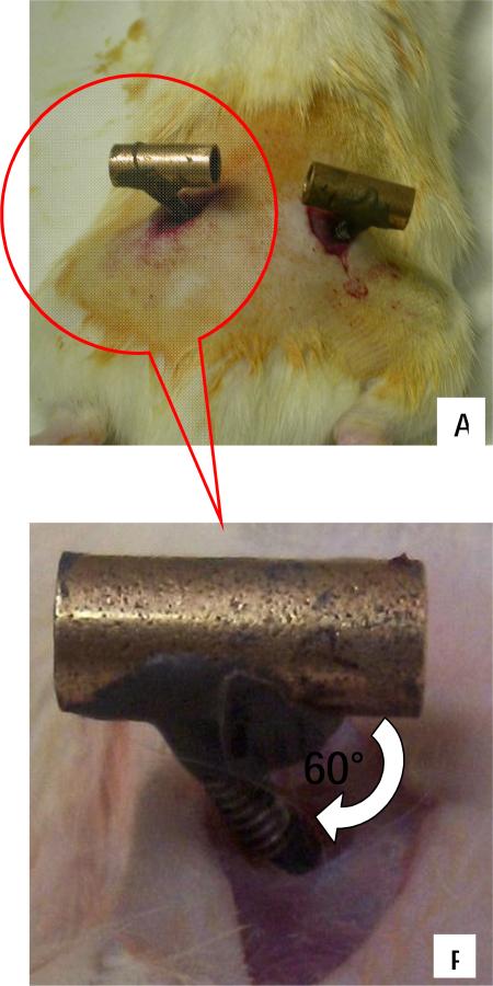
As mentioned earlier, the distal curved end of the cuff is filed back to reduce ‘overhook’. This is necessary to avoid impinging the coccygeus lateralis muscles on the ventro-medial surface of the pelvic girdle, as well as the sciatic nerve that straddles the ventral surface of the iliac process (Figure 2 F). All this is done with minimal muscle disruption through a small 'keyhole' (Figure 2D and Figure 3).
Figure 3. Surgical Images showing pelvic muscles and orthotic placement made through small incisions (Dorsal Aspect).
A) Image showing each half of the implanted pelvic orthosis from dorsal aspect. The aluminum rod is then used to connect and clamp the two halves together. B) Insert from ‘A’ showing close up of inserted screw rod of orthosis through small opening in gluteus
Using the fine-tipped scissors as a guide, the orthosis is gently slipped into the probed opening. The scissors are then removed, and by palpation the cuff of the implant is guided along the lateral surface of the iliac process until it slips under the ventral surface of the process. The implant is then gently pulled upwards to confirm that the cuff clamps the iliac. If the initial blunt dissection was without mischief to the iliacus, then the cuff would gently slip under and sit between the iliacus muscle and the iliac process (Figure 2 E and F). This procedure is then repeated on the contralateral side as well.
2.3 Clamping to the Pelvis
After surgically implanting and positioning each half of the orthosis properly (as depicted in Figure 3), the aluminum standoff is used to connect the two positioned halves via the bronze sleeves. The bronze sleeves of the implant are then squeezed together using screws in the standoff to ensure snug clamping of the pelvic bone. During this process, care should be taken to ensure that surrounding gluteus muscles are not pinched by the cuff, and that the cuff is completely embedded under the gluteus (Figure 2, Figure 3). Using alignment markings on the bronze sleeves and standoff (markings made during fabrication), the orthosis is carefully adjusted to ensure proper alignment with the pelvic girdle. Each sleeve/rod/c-clamp has 2 degrees of freedom (sliding and axial rotation) relative to the standoff. We constrain the rods/c-clamps on each side to a plane perpendicular to the body/pelvis long (rostrocaudal) axis and slide them together. Screws are then used to secure the standoff to the orthosis as noted. A tight clamp is confirmed by checking that the implant has no play in the animal's rostral-caudal direction or rotation independent of pelvis. At this stage the orthosis and pelvis should feel like a single rigid body. The skin incisions around the implant are sutured. JB QuickWeld then is applied to the sleeve-standoff joints of the orthosis in order to completely secure the implant and prevent any standoff / sleeve sliding motion, which would be possible without the screws, or the cement. The cementing prevents and displacement when retaining screws are eventually removed, and also when animal moves around, turning the orthosis into a rigid body tightly and snugly fitted onto the pelvis to make an effective rigid extension of the pelvis outside the body.
2.4 Surgical Concerns
Figure 2 E-F shows images of the muscles and nerves that are of primary concern during implantation as mentioned in the previous section. As shown in Figure 2E, in our hands, the cuff clamped the iliac without impinging the Iliacus, the femoral nerve, or the Psoas major. Also as shown in Figure 2F, the distal curved end of the cuff must just clamp the ventral surface of iliac without impinging on the coccygeus muscle and sciatic nerve. Prior to implantation, all implants were tested on museum quality rat pelvic bone samples of different sizes (Carolina Biological) to ensure proper clamp fit.
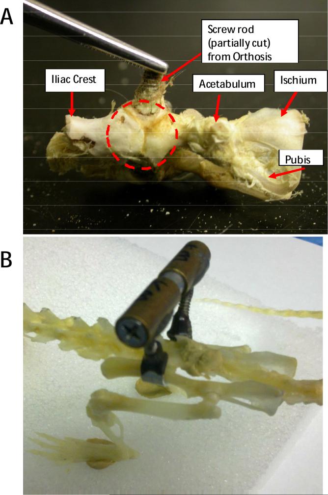
As shown in Figure 6, significant osseointegration of the iliac bone around the aluminum cuff was seen after dissection of the pelvic region approximately 6 weeks after implantation. It should be noted that although aluminum does not offer the same degree of osseointegration and biocompatibility as titanium, it sufficed for the duration of our studies (6-10weeks) as also suggested in comparison studies (Tesei et al., 2005).
Figure 6.
A. Osseointegration (in broken circle) of the Iliac bone around the Aluminum cuff in a rat pelvis explanted after rat euthanasia at ~ 6 weeks post implantation. B. Side view of a museum-type prepared rat skeleton with an implant clamped in place for comparison with A and with Figures 1 and 2, and 6A.
2.5 Postoperative Treatment
The animal was given 1.0ml/kg of 0.05mg/ml buprenorphine subcutaneously, every 12 hours for the next 48 hours following surgery. Intramuscular(IM) 0.5ml/kg prophylactic antibiotics (Dilute 3.4ml of Sterile water (diluent) with 1g of ampicillin vial) were also administered once a day for a week. 2-3ml Lactated Ringer was given subcutaneously for the next 48 hours following surgery and continued for a week only if the animal is not drinking fluids on its own. The implant-tissue interface was constantly monitored and cleaned daily to prevent irritation and infection. Sterile saline and Q-tips were used in combination to flush and debribe around the incision/stitches. A combination of Lidocaine and Neosporin crèmes were used daily after flushing to reduce irritation and infection of the area. If necessary, Elizabethan collars or Yuk-spray around the implant were used to prevent the animal from disturbing the implant and incision site for the 2 weeks of recovery. We have found that 2-3 weeks is a reasonable time for complete surgical healing and some osseointegration of the orthosis with the pelvic bone. Infection rates at the implant in intact rats are very rare (<2%) and in spinalized rats have been below ~5%, despite higher risks due to the injury effects on autonomic control and the lack of controlled continence in their bedding materials.
2.6 Kinematic Recording and Analysis (Pre- and Post-implantation)
8 adult female Sprague–Dawley rats were used for the validations and locomotor kinematic comparison prior to, and post implantation. Visual assessments indicated no evident deficit in the animals’ ability to locomote on a treadmill after implantation. This was further confirmed by assessing the stepping kinematics of the animal on a treadmill before implantation and then 2-3 weeks post implantation. We evaluated the angular excursions of the hip, knee and ankle, as well as the stance, swing, and cycle durations using a customized 2D motion capture system. The right hindlimb and pelvic region were shaved to improve the visual image obtained for analysis. Five 3-4mm diameter spherical reflective disks (B&L Engineering, Tustin, CA) were placed on the skin of lateral side of right hindlimb overlaying the iliac crest, the greater trochanter, the knee joint, the lateral malleolus, and fifth metatarsal head. The same person performed all marker placements to avoid variability. To minimize the effects of skin slippage over the knee, the ‘true’ knee joint was computed from video by using the actual lengths of the femur and tibia and triangulation algorithm using the hip and ankle makers (Filipe et al., 2006; Pereira et al., 2006). The markers on the rat were illuminated with two infrared light sources (Model S-1800 by Pinecom) and a high-speed digital image camera (JAI TM-6710CL) was used to record motion of the lateral side of right hindlimb in the sagittal plane (10” × 13”) at 100 frames/sec. Motion tracking-analysis software (Maxtraq 2D by Innovision systems) and a numerical computing package (MATLAB R2008, Mathworks) were used to compute joint kinematics. Treadmill speed was set at 20-25cm/s (Canu et al., 2005) and 3-5 two minute satisfactory continuous walking trials were recorded for each rat (~360-600 steps).
Normative step cycle data has been published (Thota et al., 2005). Previous studies have also shown that limb length and limb orientation (i.e the polar relationship (magnitude and angle) between the hip joint at the greater trochanter marker and the foot marker at the fifth metatarsal head) might provide independent predictors of limb coordination and stepping cues (Goldberger, 1988; Pereira et al., 2006). Consequently, the four phases within a step cycle (E1, E2, E3 & F) were determined by using the limb length and orientation excursions of the tracked right hindlimb motion. The peak and trough of the limb orientation coincides with toe contact (E2 onset) and toe off (F onset) events respectively. The peak of the differential of the limb orientation coincides with E1 onset. Between toe contact and toe off events, the positive abscissa intersection point of the limb length differential coincides with the onset of E3 phase. Typically, these transitions between E1, E2, E3 & F step phases appear to roughly coincide with the crests and troughs of the ankle kinematics.
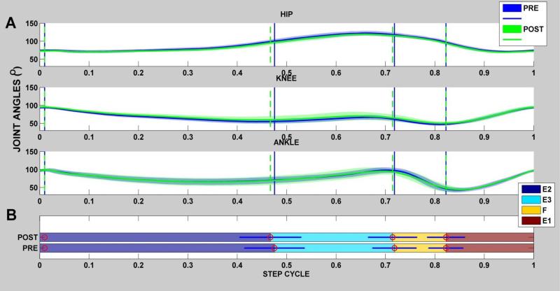
All steps for each rat were divided into the four phases. All steps were then normalized to 1 step cycle and averaged together to yield an averaged step for each individual rat as shown in Figure 4A,B (Goldberger, 1988; Pereira et al., 2006). The mean percentage of each phase's contribution to whole step cycle was also then determined for each rat individually (Figure 4 B). These measures constitute the temporal gait parameters, and were obtained for each rat prior to and after orthotic implantation. In addition, the angular values at the beginning of each phase were measured and analyzed for the averaged step cycle for each rat (Figure 6).
Figure 4. Hindlimb Joint Kinematics and their variations for single rat walking at the test speed (Rat N004).
Example of temporal gait measures obtained for a single rat (rat N004 )prior to (pre) and after orthotic implantation (post). A)For the pre (blue joint excursion)) and post (green excursion), all joint excursions were normalized to 1 step cycle and averaged together to yield the average joint angles as shown in the hip, knee & ankle joint plots above. in rat N004, all steps in sample records were divided into four phases (E2,E3,F,E1) and the mean duration for each phase was determined as shown by vertical lines in the joint angle plots in ‘A’. The Horizontal bar plot shows the mean percentage of each phase's contribution to the whole step cycle and analyzed for the averaged step cycle for each rat. Significance was set at p< 0.05. As shown the duration of each phase was not significant in the pre and post conditions in this rat.
Statistics
We used repeated measures ANOVA to determine if there were significant pre-post differences in our various measures of treadmill kinematics for the rats, using SPSS for statistical calculation. For all statistical evaluations including repeated measures ANOVA and paired t-tests, the level of significance was set at p< 0.05. For the post hoc paired t-tests, following the ANOVA, Bonferroni correction was employed.
3. Results
Pelvic Implant effects on stepping after recovery from surgery in the 8 validation rats were minimal or absent.
3.1 Temporal measures
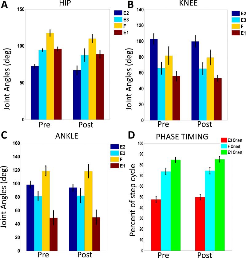
Figure 4 shows an example of the pre and post angular excursions over the averaged step cycle in all hindlimb joints for one animal (Rat N004). To identify possible gait alterations due to the pelvic implant and surgery we compared temporal gait variables pre- and post-pelvic implantation for all animals through repeated measures ANOVA. The temporal variables evaluated were the mean step duration, mean stride length (not plotted) and the mean percent onset of each phase ( shown for the population in Figure 5D). As shown in Figure 5, the group's mean percent onset of each phase within the step cycle showed no significantly different pre-post effect in ANOVA for all the rats (F(1,7) = 1.047, p = 0.340,). Similarly, the step duration after pelvic implantation was not significantly different pre-post for the ANOVA in all rats (F(1,7) = 2.682 , p = 0.145,). There were also no significant changes pre-post seen in the ANOVA for stride length after implantation (F(1,7) = 2.899 , p = 0.132,). Basic features of stepping were unaltered.
Figure 5. Comparison of averages of joint kinematics and the onset of each step phase for all rats.
A-C. Joint Angles. Each plot shows the means and standard deviations of the angular value at the onset of each step phase for all rats over the averaged step cycle (600 steps) before and after pelvic implant surgery. There are no significant changes seen in any of these values after pelvic implant surgery (A. Hip, p = 0.068; B. Knee, p= 0.49; C. Ankle, p=0.68 ). D. Timing as percent of step cycle of each phase onset. There were no significant differences in timing (p=0.141). Taken together, step cycle kinematics in the group were unaltered. Step duration and stride length were also unaltered (see text).
We next tested the individual rats' parameters in paired t-tests, first without Bonferroni corrections, to 'cast the largest net' for any individual effects, then with Bonferroni. It should be noted that in the individual uncorrected tests all but one rat (specifically, Rat# N002) also showed no difference in any of the temporal measures. However, Rat N002 showed a small but significant change, which also retained significance after Bonferroni correction . This was an alteration in percent phase onset occurrences within the step cycle, thus indicating a slight phase shift in the joint kinematics. These differences were only significant at the onset of the F and E1 phases for Rat N002. The change in stride length for rat N002 was also significant tested with the Bonferroni correction. Despite these changes seen in rat N002, the step cycle durations before and after implantation were not significantly different. In addition, besides the phase shift seen in the angular excursions of the hindlimb joints for rat N002, the general angular excursion pattern remained unchanged without any artifacts in the excursion pattern. Rat N002 kinematic parameters, even those significantly differing within Rat N002 after implantation, in the corrected paired tests, remained within the normal range of variation of the group of rats.
3.2 Joint Kinematics
The plots in Figure 5 A-C show the means and standard deviations of the hindlimb joint kinematics measures at the onset of each step phase for all rats over the averaged step cycle. As shown, there were no significant differences in pre-post behavior of joint angle data in the ANOVAs for angular values at onset of each phase for the hip, knee, and ankle joints (Hip F(1,7) = 4.642 , p = 0.068; Knee F(1,7) = 0.830, p = 0.393; Ankle F(1,7) = 0.183, p = 0.682,). This lack of significant change was also observed in post-hoc measures in the rats and was not specific to any particular phase or joint. Furthermore, the overall angle excursion pattern for each joint remained unchanged for each rat in the pre and post conditions as shown in the example rat in Figure 4 . All joint angles typically yielded and peaked at approximately the same points in the step cycle, maintaining the general excursion profile and phase transition timing as highlighted in the temporal measure results. This clearly suggests that there was no mischief from the implant to significantly alter the natural timing and angular kinematic profile of the rats.
In conclusion, we have successfully demonstrated the viability of our pelvic orthosis design and implantation in the intact rat. The absence of significant perturbation of step kinematics supports the possibility of direct skeletal interaction of robots using this orthosis (Song and Giszter, 2011). We have also successfully implanted the orthosis in both adult spinalized and adult rats spinalized as neonates in a variety of other studies without any issues(Hsieh and Giszter, 2011; Udoekwere et al., 2006). Finally, despite the significant forces applied at the pelvis via the orthosis using our robotic system, the implanted orthotics has proven to be quite durable and stable for durations as long as 3 months in various studies in our group and also to osseointegrate (Figure 6A).
4. Discussion
Our goal in this paper has been to present the methods of construction, implantation and a validation procedure for an implanted orthosis that we have used successfully in a number of published studies over a number of years [see below], so that it can be employed more broadly by the community when applicable. More specifically, we have described methods of implantation and validation of an implant into the pelvis of rats which allows direct force application to the pelvis. Osseointegration of the implant and the absence of, or minimal nature of, perturbations of stepping that result from the implant suggest that rats experience no difficulty or problems with the implant's presence in motor or sensory terms. The force application to the rat bypasses cutaneous and muscular tissues in the rat. In this way our orthosis avoids various cutaneous and proprioceptive reflex effects that might otherwise ensue, and may contribute to interactions with the actuation in other robotic interaction systems. Our validation data support the lack of perturbation to normal stepping processes in intact rats. We recommend validation of the surgical implantation process first in intact rats, whatever the final target preparation, and recommend this with novice surgeons for this procedure. This is because the intact rat shows great initial sensitivity to perturbations and their fully conscious sensations cause compensations in response to faulty or poorly placed implants that might be absent in other preparations such as full spinalization. We found almost no change whatsoever in 8 rats prepared by an experienced surgeon: Joint angle trajectories were unaltered and only one rat out of eight showed any detectable change in step temporal features or stride length. These changes were very minor and lay within the normal range of variation within the group as a whole. There were no alterations in step duration, or mean percent onset of most phases in the one rat. There was a minor change in this single rat, with any alterations occurring in onset of the F and E1 phases and stride length. Such changes can be detected prior to any experimental use of the orthosis if necessary, We included the small statistical effect in rat N002 in the results here for completeness. In this one perturbed rat that we observed, the effects represented a minor but significant change relative to the prior pattern but, we must emphasize, the parameters remained within the normal range of variation of the group of rats.
The implant methods we have described provide a means of taking partial kinetic control of a key element of the rat's musculoskeletal plant: the pelvis. The application of forces in extrinsic (world) or intrinsic (body centered) coordinates to the pelvis enabled by the orthosis allows a range of experimental interventions and strategies. Several of these have been used to good effect by our group. We have tested a pelvis-based brain machine interface system and adaptations using this implant (Song and Giszter, 2011; Song et al., 2009). We have tested robot rehabilitation of complete spinal transected rats using the implant (Udoekwere et al., 2006). We have tested robot-driven epidural stimulation in spinal transected rats using the implant (Hsieh and Giszter, 2011; Song and Giszter, 2011; Song et al., 2009; Udoekwere et al., 2006). The implant is also clearly well-suited to many additional novel applications. Avoiding stimulation of skin, muscle or significant mechanical alteration and clamping of soft tissues by slings, tubes, and back-pack or corset-like trunk attachments is a significant advantage. It is easier to quantify interactions and understand stabilization because 'single port' rigid body interactions occur, without altering other sensory or mechanical regimes in the rat. The ossseointegration of the implant and the direct application of force to bone is well suited to experiments simulating an exoskeleton effect, a virtual muscle, a virtual leg, and various other application possibilities, important for understanding rehabilitation and plasticity, fundamental mechanisms of movement and sensorimotor integration, and brain machine biomechanical integration processes.
The orthotic device we present might easily be added to other rodent robotic model frameworks in the literature used to provide animal models of human rehabilitation [e.g., see (de Leon et al., 2002; Dominici et al., 2012; Hogan and Krebs, 2004; van den Brand et al., 2012)]. In our hands, the orthosis is used with 3 DOF and 6DOF phantom 1.0, 1.5 robots. However, the orthosis is easily adapted to other systems to avoid cutaneous and soft tissue pressure and alteration in trunk interaction in quadrupedal motor activities.
In conclusion, the construct and surgical procedure detailed here enables a novel framework for rodent sensorimotor testing when coupled with haptic quality robotics, and neural recording and stimulation techniques. .
Highlights.
The construction of a pelvic orthosis for rats from readily available standard machine parts is described.
The surgical implantation procedures and pitfalls are described for easy replication.
The resulting orthosis allows easy attachment of a range of standard robotic or other devices. We show a standard Phantom premium 1.0 attached.
Kinematic step cycle parameter validation of the implant's minimal effect on locomotion and evaluation methods are described. These are applied to 8 rats implanted with the orthosis by a trained surgeon using the techniques in the paper.
ANOVA shows no implant effects or perturbation of stepping.
Post-hoc paired t-tests, without Bonferroni correction, used to 'destruction test' the lack of effect of implants show no effect in 7 of 8 rats and a small but significant effect of the implant on step phasing in one rat, that nonetheless remained within the population range of variation.
The described implant osseo integrates well and causes no discomfort or problems in locomotion and thus allows a range of biomechanical, brain machine interface, neurobotic and rehabilitation robotic applications to be explored in a robust animal model.
Acknowledgements
Early design of pelvic orthoses, which were further refined over time for the work here, were due to work of Joan Young and Jonathan Scabich in preliminary tests working in our group, and were are highly indebted to their pioneering efforts. Supported by NIH NS054894 and 072651.
Footnotes
Publisher's Disclaimer: This is a PDF file of an unedited manuscript that has been accepted for publication. As a service to our customers we are providing this early version of the manuscript. The manuscript will undergo copyediting, typesetting, and review of the resulting proof before it is published in its final citable form. Please note that during the production process errors may be discovered which could affect the content, and all legal disclaimers that apply to the journal pertain.
References
- Canu MH, Garnier C, Lepoutre FX, Falempin M. A 3D analysis of hindlimb motion during treadmill locomotion in rats after a 14-day episode of simulated microgravity. Behav Brain Res. 2005;157:309–21. doi: 10.1016/j.bbr.2004.07.009. [DOI] [PubMed] [Google Scholar]
- de Leon RD, Kubasak MD, Phelps PE, Timoszyk WK, Reinkensmeyer DJ, Roy RR, Edgerton VR. Using robotics to teach the spinal cord to walk. Brain Res Brain Res Rev. 2002;40:267–73. doi: 10.1016/s0165-0173(02)00209-6. [DOI] [PubMed] [Google Scholar]
- Dominici N, Keller U, Vallery H, Friedli L, van den Brand R, Starkey ML, Musienko P, Riener R, Courtine G. Versatile robotic interface to evaluate, enable and train locomotion and balance after neuromotor disorders. Nat Med. 2012;18:1142–7. doi: 10.1038/nm.2845. [DOI] [PubMed] [Google Scholar]
- Filipe VM, Pereira JE, Costa LM, Mauricio AC, Couto PA, Melo-Pinto P, Varejao AS. Effect of skin movement on the analysis of hindlimb kinematics during treadmill locomotion in rats. J Neurosci Methods. 2006;153:55–61. doi: 10.1016/j.jneumeth.2005.10.006. [DOI] [PubMed] [Google Scholar]
- Goldberger ME. Partial and complete deafferentation of cat hindlimb: the contribution of behavioral substitution to recovery of motor function. Exp Brain Res. 1988;73:343–53. doi: 10.1007/BF00248226. [DOI] [PubMed] [Google Scholar]
- Hogan N, Krebs HI. Interactive robots for neuro-rehabilitation. Restor Neurol Neurosci. 2004;22:349–58. [PubMed] [Google Scholar]
- Hsieh FH, Giszter SF. Robot-driven spinal epidural stimulation compared with conventional stimulation in adult spinalized rats. Conf Proc IEEE Eng Med Biol Soc. 2011;2011:5807–10. doi: 10.1109/IEMBS.2011.6091437. [DOI] [PMC free article] [PubMed] [Google Scholar]
- Pereira JE, Cabrita AM, Filipe VM, Bulas-Cruz J, Couto PA, Melo-Pinto P, Costa LM, Geuna S, Mauricio AC, Varejao AS. A comparison analysis of hindlimb kinematics during overground and treadmill locomotion in rats. Behav Brain Res. 2006;172:212–8. doi: 10.1016/j.bbr.2006.04.027. [DOI] [PubMed] [Google Scholar]
- Song W, Giszter SF. Adaptation to a cortex-controlled robot attached at the pelvis and engaged during locomotion in rats. J Neurosci. 2011;31:3110–28. doi: 10.1523/JNEUROSCI.2335-10.2011. [DOI] [PMC free article] [PubMed] [Google Scholar]
- Song W, Ramakrishnan A, Udoekwere UI, Giszter SF. Multiple types of movement-related information encoded in hindlimb/trunk cortex in rats and potentially available for brain-machine interface controls. IEEE Trans Biomed Eng. 2009;56:2712–6. doi: 10.1109/TBME.2009.2026284. [DOI] [PMC free article] [PubMed] [Google Scholar]
- Tesei L, Casseler F, Dreossi D, Mancini L, Tromba G, Zanini F. Contrast-enhanced X-ray microtomography of the bone structure adjacent to oral implants. Nuclear Instruments and Methods in Physics Research Section A: Accelerators, Spectrometers, Detectors and Associated Equipment. 2005;548:257–63. [Google Scholar]
- Thota AK, Watson SC, Knapp E, Thompson B, Jung R. Neuromechanical control of locomotion in the rat. J Neurotrauma. 2005;22:442–65. doi: 10.1089/neu.2005.22.442. [DOI] [PubMed] [Google Scholar]
- Udoekwere UI, Ramakrishnan A, Mbi L, Giszter SF. Robot application of elastic fields to the pelvis of the spinal transected rat: a tool for detailed assessment and rehabilitation. Conf Proc IEEE Eng Med Biol Soc. 2006;1:3684–7. doi: 10.1109/IEMBS.2006.259633. [DOI] [PMC free article] [PubMed] [Google Scholar]
- van den Brand R, Heutschi J, Barraud Q, DiGiovanna J, Bartholdi K, Huerlimann M, Friedli L, Vollenweider I, Moraud EM, Duis S, Dominici N, Micera S, Musienko P, Courtine G. Restoring voluntary control of locomotion after paralyzing spinal cord injury. Science. 2012;336:1182–5. doi: 10.1126/science.1217416. [DOI] [PubMed] [Google Scholar]


