Abstract
Integration of sensing capabilities with an interactive signage through wireless communication is enabling the development of smart packaging wherein wireless (13.56 MHz) power transmission is used to interlock the smart packaging with a wireless (13.56 MHz) reader or a smart phone. Assembly of the necessary componentry for smart packaging on plastic or paper foils is limited by the manufacturing costs involved with Si based technologies. Here, the issue of manufacturing cost for smart packaging has been obviated by materials that allow R2R (roll-to-roll) gravure in combination with R2R coating processes to be employed. R2R gravure was used to print the wireless power transmission device, called rectenna (antenna, diode and capacitor), and humidity sensor on poly(ethylene terephtalate) (PET) films while electrochromic signage units were fabricated by R2R coating. The signage units were laminated with the R2R gravure printed rectenna and sensor to complete the prototype smart packaging.
Presently, information on packaged goods is available only as static printed information1. The ability to actively sense the status of contents in the packaging and wirelessly communicate that information would enable more effective logistics and quality control. The development of active packaging systems wherein the ability to provide updated information via wireless means such as wireless (13.56 MHz) power transmission tool, housed in a smart phone, provides a powerful new dimension. To achieve this, signage, the wireless power transmission unit and sensor must be integrated in packaging sheets with low cost and disposability. In other words, there is a need to implement devices on packaging plastic or paper foils to wirelessly and instantaneously communicate with the surroundings and display updated information. However, the cost to achieve this using currently available Si technology is prohibitive. There is a need therefore to develop new materials and fabrication protocols to enable the development of wirelessly driven smart packaging with extremely low cost. To realize the extremely low cost of the smart packaging, the roll-to-roll (R2R) printing of electronic devices on to packaging needs to be implemented. Electronic devices such as wireless power supply, sensor, radio transponder, and signage should be R2R printable to lower manufacturing and labeling costs. To date, only a few R2R printable electronic devices have been reported. Printed wireless power transmission device operated at 13.56 MHz2, all printed RF (radio frequency) 1 bit tone generator3, printed logic circuits4,5and electrochromic display6,7and sensors wherein simple color changes are induced by temperature changes or selected gas detection have been produced using R2R printing8,9. However, to the best of our knowledge, no reports on fully printed smart packaging wherein wireless power supply, sensor, radio transponder and signage are all R2R printed on plastic foils have appeared. The use of R2R printing to fabricate wireless electronic devices faces various challenges such as the limited accuracy in overlay printing registration10, R2R web handling11, deformation of the web12 and heterogeneity in the electrical characteristics of printed devices13.
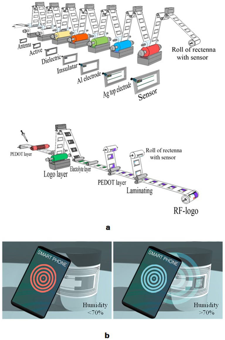
Here, we describe materials and fabrication protocols to fabricate the basic concept model of wireless (13.56 MHz) enabled smart packaging where the rectenna (wireless power supply), humidity sensor and simple electrochromic signage are integrated on a poly(ethylene terephthalate) (PET) film using R2R processes as illustrated in Figure 1a. This prototype model is specially designed to address the limitations described above by employing large device dimension such as 1 mm antenna line width with 0.5 mm of line space and a R2R gravure friendly structure for the diode with a wide active layer to minimize misalignment of the R2R gravure printed Al top electrodes. A total 5 layers of R2R gravure printing and 4 layers of R2R coating using 8 different electronic inks (Figure 1a) are needed to complete the tag to demonstrate the basic working concept of the smart packaging: wireless power supply, sensor and signage. With the 13.56 MHz wireless reader in proximity to the all printed smart packaging system, the printed 13.56 MHz antenna couples AC power from the smart phone. The coupled AC is converted to DC by passing through a printed diode and capacitor; the rectifier. The converted DC power is regulated by the printed humidity sensor with the power delivered to the electrochromic signage dependent on the relative humidity of the environment (Figure 1b).
Figure 1.
(a). Scheme for R2R gravure to completely print the model of the smart packaging on PET foils. At the first R2R gravure printing unit, Ag nanoparticle based silver ink used to print antenna, wires and bottom electrodes and then, ZnO based ink was used to print on the printed bottom electrodes at the second printing. At the third printing unit, dielectric layers for capacitors were printed on the printed bottom electrodes unit using BaTiO3 nanoparticle based ink. At the fourth printing unit, the insulating layers for crossing wires and junctions to connect printed antenna and diodes were printed using epoxy based ink, and Al particle based ink was used to print top electrodes on printed ZnO layer to complete the diodes at the fifth printing unit. At the sixth printing unit, top electrodes and wires were printed using silver nanoparticle based ink and then, finally humidity sensors were printed using conducting polymer based ink. The roll of fully R2R gravure printed rectenna was laminated by the electrochromic signage units, fabricated R2R coating process on PET. In the R2R coating process to fabricate the signage, first PEDOT:PSS ink was used to coat the conducting layers and then the signage images were patterned using poly(methyl methacrylate) based ink. Finally, the coated PEDOT layers were laminated on previously patterned PEDOT films. (b). Schematic working concept of wireless-signage-sensor tag; wirelessly display QR code only above 70% of humidity.
Results
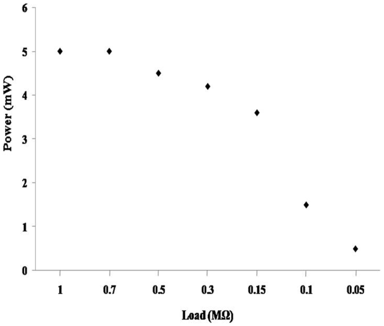
The most critical issue in R2R gravure printed rectenna (antenna, diode and capacitor) is to provide sufficient DC power (3 mW) to display the electrochromic logo “QR code”. The converted DC power attainable from the coupled 13.56 MHz AC using the wireless 13.56 MHz reader is strongly dependent on the Q factor of the printed antenna and the resistance load of the electrochromic logo14. R2R gravure printed antenna structures (as shown in Figure S1 in the Supplementary Information) were obtained using the silver ink and were tested to find the optimal (coupled AC of 44 V: refer the results in Figure S2 for optimized R2R gravure printed antenna in the Supplementary Information) using a custom made 13.56 MHz reader (ECMA-356 Standard). The Q factor of the optimal antenna based on the given silver ink on PET foils was 13 based on Q = 1/R (L/C)1/2 where R, L and C are respectively the resistance, inductance and capacitance of the printed structure (Fgure S2 and Table S1 in the Supplementary Information). In the printed rectenna in this work, the optimized load, resistance of the electrochromic logo, is about 150 kΩ to enable supply of DC power of 3 mW. Figure 2 shows the output DC power obtained using various values of load resistors and the R2R gravure printed rectenna in this work. Under the given R2R gravure printed antenna, electrodes and capacitors, about 80% of the printed rectenna can provide 3 mW of power with more than 150 kΩ of load. The low device yield is attributed to limitations in the overlay printing registration and can be improved by using R2R gravure, equipped with higher registration accuracy controller.
Figure 2. Rectified DC powers from coupled AC 13.56 MHz according to various resistances of loads.
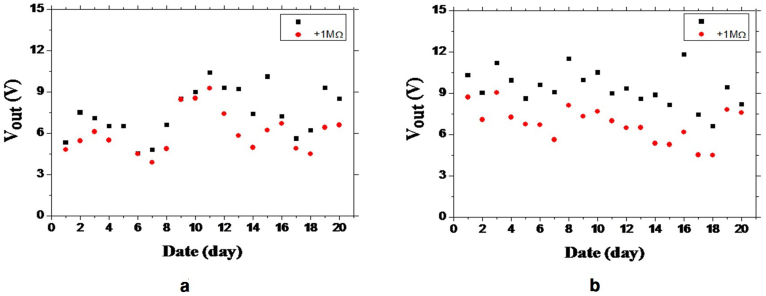
To demonstrate the concept of smart packaging, the stability of the DC power from the printed rectena is extremely important. It was found that the printed antenna and capacitance are very stable for 6 months under ambient conditions. The reliability and stability of printed diodes are critical factors for the successful demonstration of all printed wireless-sensor-signage tag on PET foils. To test the stability of printed diodes, it was necessary to first define which printed layer was the most critical one for providing the stability of the diodes. Among the three printed layer: silver bottom electrode, ZnO-polyaniline hybrid active layer and the Al top electrode, the latter proved the most critical in attaining a stable rectified DC voltage. The printed Al layer was found to form oxide layers under ambient conditions resulting in the output current of the printed diode rapidly declining with time. To retard the oxidation of Al ink, various polymer additives were tested (see results Figure S3 for stability tests on printed rectenna in the Supplementary Information), as shown in Figure 3. The stability of printed diodes with epoxy resin containing Al ink was compared with the diode with vapor deposited Al film as top electrodes without and with loading of 1 MΩ. Both diodes delivered stable output currents (Figure 3a and b). This result is indirect evidence that the oxidation of printed Al top electrodes can be retarded by appropriate selection of polymer additive in Al ink.
Figure 3. Rectified DC outputs from the stability tests of printed diodes by using top electrodes respectively prepared by vapor deposited Al film (a) and gravure printed Al inks with epoxy additive (b) with infinite resistance (black cube) and 1 M ohm of load (red circle).
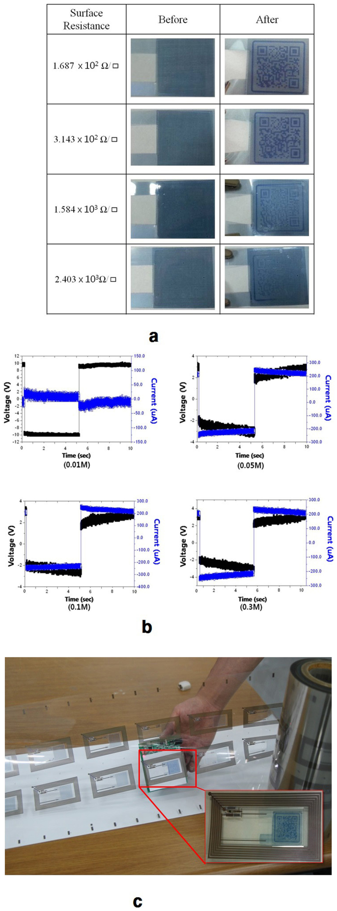
To clearly show the function of the electrochromic display prepared by the R2R coating process (Figure 1a), the wirelessly transmitted DC power should be sufficient to drive the redox reaction to produce a vivid color change. Therefore, PEDOT:PSS was selected as the active layer since a vivid color change is observed under the voltage of less than 2 V at 100 μA6,7. Furthermore, PEDOT:PSS is commercially available in large quantity at reasonable cost. In the oxidized state, PEDOT has a light blue, close to transparent, color while in its reduced state, it is dark blue15,16. A vivid QR-Code image also depends on the quality of R2R coated PEDOT:PSS layers shown in Figure 4a. The clarity of the QR-Code displays obtained with various surface resistances (varying thickness) of R2R coated PEDOT:PSS were tested using the same power of the printed rectenna. The QR-Codes were clearly revealed at surface resistances below 1.6 kΩ/sq for coated PEDOT:PSS layers under the same electrolyte concentration. A surface resistance (<2 kΩ/sq) for R2R coated PEDOT:PSS is a prerequisite for effective electrochemical switching. After attaining an optimal R2R coating condition for PEDOT:PSS, the electrolyte and insulating layer for QR-Code images and top electrode are consequently R2R coated to give the QR-Code as shown in Figure 4a. The concentration of electrolyte, LiClO4, in the poly(ethylene oxide) (PEO) gel influences the speed of the redox reaction of coated PEDOT:PSS17,18; as on increasing the LiClO4 concentration from 0.01 M to 0.05 M, the color change (redox reaction) could be completed in 5 s at 0.05 M of electrolyte but not at 0.01 M where no current was flowing via the electrolyte gel (Figure 4b). Furthermore, no faster rate of color change was observed even at higher concentrations as shown by results in Figure 3b19,20. By simply laminating the resultant electrocromic signage with the R2R gravure printed rectenna (Figure 4c), the fully printed wireless 13.56 MHz available QR-Code can be completed. The resultant wireless-signage (QR Code) can clearly display the QR Code at more than 90% yield close by the wireless 13.56 MHz reader since the printed rectenna wirelessly provides DC power from the wireless 13.56 MHz reader to reduce the PEDOT:PSS of electrochromic signage to display the QR-Code image with high contrast (inset in Figure 4c). Based on this all printed wireless-QR-Code, the humidity sensor was gravure printed at a position between the diode and signage to regulate the power of the DC to turn on the signage since the resistance of the sensor was designed to be sensitive to the relative humidity.
Figure 4.
(a). Electrical characteristics of a R2R coated electrochromic display. (b). The speed of displaying signage under various LiClO4concentrations in the PEO gel. (c). R2R samples by combining R2R gravure printed rectenna and R2R coated electrochromic signage (Demonstration video is available by clicking image).
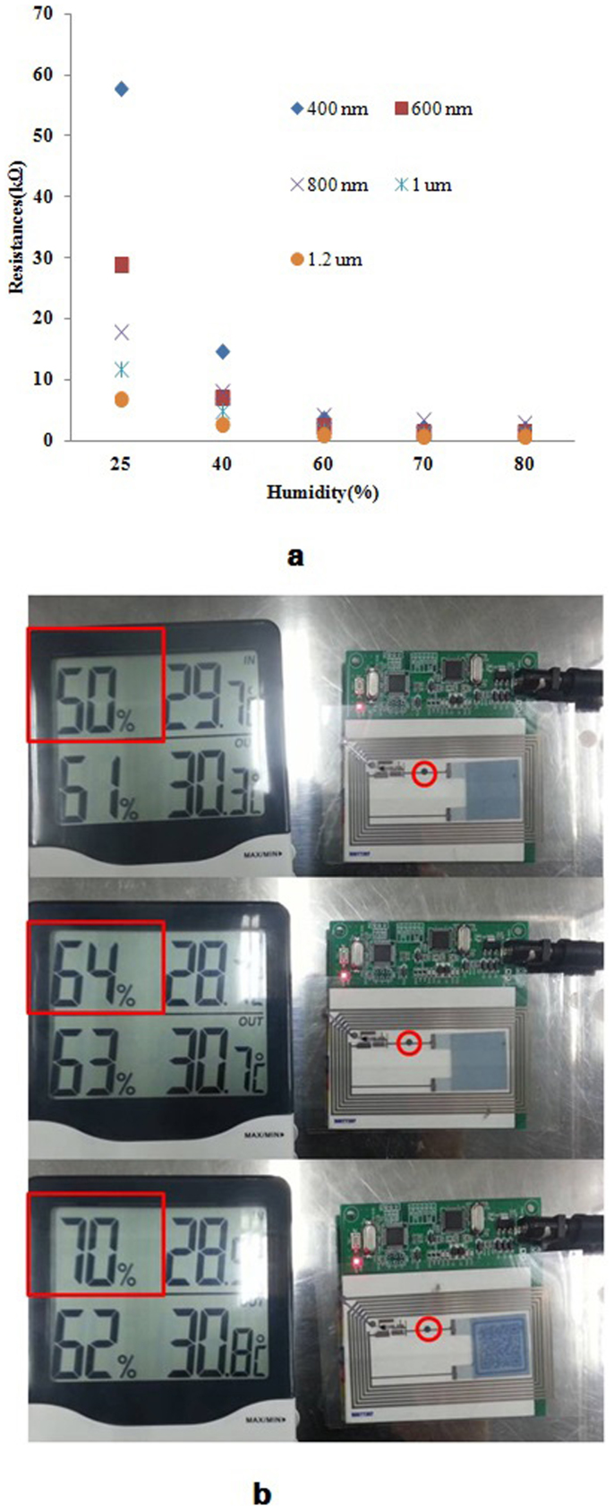
The humidity sensor was simply gravure printed or simply fabricated by dropping commercially available conducting ink (PH-001, Paru Co. Korea) that can quickly adsorb water molecules from the surroundings and enhance the conductivity via increasing ionic conductivity21,22. The response of the humidity sensors were found to be dependant on the printed thickness as shown in Figure 5a. To achieve a clear indication of a change in the humidity, a 400 nm thickness was selected. In this work, to completely demonstrate the concept of the smart packaging, the printed humidity sensor was gravure printed in the wireless-QR-Code. The printed humidity sensors as a switch can only turn on the QR-Code when the humidity is over 70% by regulating the power available to electrochemically reduce the patterned PEDOT:PSS. The characteristics of the printed wireless-QR-Code-sensors are shown in Figure 5b. The printed wireless-QR-Code-sensor tags would not display the QR-Code under low humidity (<70%) but display the QR-Code at higher humidity (>70%) (refer the Figure S4 to view the demonstration movie). Based on fully R2R gravure and coating system, the prototype of the smart packaging, wireless-QR-Code-humidity sensor, can be manufactured with low cost.
Figure 5.
(a). Resistances of printed sensors with various thickness and humidity. (b). The working image of all printed wireless-sensor-signage tag to show the concept of wirelessly sensing 70% of relative humidity and display the sensed information using wireless 13.56 MHz reader (red circle indicates printed humidity sensor).
Discussion
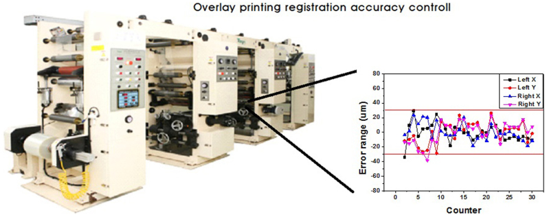
We describe here a R2R gravure system with the incorporation of a R2R coating process to manufacture a prototype smart packaging wherein 13.56 MHz antenna, diode, capacitor, electrochromic signage and humidity sensor are integrated on PET foils. The prototype smart packaging system was designed to minimise the impact of limited registration accuracy of commercially available R2R gravure wherein an error range of ±40 μm is encountered (Figure 6). The R2R coating process for fabricating electrochromic signage can be substituted by R2R gravure printing process for practical manufacturing as shown in Figure S5 in the Supplementary Information. Here, the all-printed wireless-QR Code-humidity sensor tag displays the QR-Code only above a humidity of 70%. However, the humidity level that induces switching can be tuned by varying the thickness of the printed sensor. Furthermore, printed humidity sensor is just the example at used here. A variety of printed sensors such as a range of gas sensors could be used to detect food quality in packaging. Therefore, the R2R gravure printed wireless-QR Code-sensor tag will be used as the platform of simple smart packaging to wirelessly sense targeted stimuli and display appropriate information. These results demonstrate the concept model of smart packaging that has the possibility to open new research fields and packaging markets. Although this model is still some way from use with current smart phones, complete wireless interlocking of the R2R printed smart packaging with a smart phone could be used instead of traditional packaging in the near future. To be compatible with the smart phone, a simply printed diode in the wireless-signage-sensor tags needs to be improved for supplying 3 mW of power from the commercially available smart phone or the power needed to drive the printed signage should be lower.
Figure 6. Actual image of R2R gravure printer (R2R gravure machine from Taejin Co., Korea and servomechanism units from i-PEN, Korea) used in this work with the attained overlay printing registration accuracy on PET web with the printing speed of 8 m/min where x means machine direction and y is for transverse direction on two points of the web.
Methods
For R2R printing wireless-signage-sensor tags on PET foils using all commercially available inks (as shown in Figure 1a), the unit of wireless power supply was first R2R gravure printed on poly(ethylene terephtalate) (PET) using R2R gravure with 2 printing units shown in Figure 6 (Taejin Co., Korea). The first R2R gravure printing unit prints the 13.56 MHz antenna, electrodes for diode and capacitor, and wire were all R2R gravure printed using silver nanoparticle based ink (PG-007, Paru Co. Korea). A printing speed of 8 m/min, roll pressure of 0.8 MPa and web tension of 10 Kgf was employed to print onto the PET web (with 75 μm of thickness). After printing, this is continuously passed through the heating chamber (150°C) for 5 s curing. The printed web is continuously transferred to the second gravure printing unit to print dielectric layers for capacitor using BaTiO3 nanoparticle based ink (PD-100, Paru Co. Korea) and then, further print ZnO based semiconducting ink (PR-070 Paru Co. Korea) on printed Ag electrodes. Al top electrodes were then printed using Al ink (PA-009, Paru Co. Korea) on printed ZnO layers while Ag top electrodes were printed on previously printed BaTiO3 dielectric layers on PET foils (purchased from Toray Saehan Inc. Korea) with a thermal shrinking of 1.0% to R2R machine direction and 2.0% to transverse direction during R2R gravure printing in this work. For preparing the electrochromic signage, a solution of PEDOT:PSS, purchased from Aldrich, was adjusted for wetting on a PET surface by adding 10 mL of 2-propanol into 100 mL of PEDOT:PSS solution with vigorous mechanical stirring. The resulting PEDOT:PSS solution was used for R2R coating on PET foils at a speed of 8 m/min and PEDOT:PSS coated PET foil was cured at 150°C by passing through a heating chamber. The PEDOT:PSS coated film was further screen printed using PMMA ink with a viscosity of 10,000 cp (PMMA with Mw of 300,000 was purchased from Aldrich and then 10 g was dissolved into 100 mL of Butylcabitol from Aldrich) to make QR-Code pattern. The resulting printed QR-Code pattern was further coated by electrolyte ink with a viscosity of 1,000 cp (mixed 100 mL of water with 1 g of PEO with Mw of 10,000 (Aldrich) and 1.06 g of LiClO4 (Aldrich) using a mechanical stirrer). Finally, the PEDOT:PSS coated film was used to cover the top of the electrolyte printed film to use as a signage.
Author Contributions
H.K. and G.C. wrote the main manuscript text. H.K., H.P. Y.P. and M.J. performed the experiments and prepared figures 1-5. B.K. and G.W. helped for the design of electrochromic signage and the formulation of inks for printing the electrochromic signage in figures 3 and 4. M.J. All authors reviewed the manuscript.
Supplementary Material
Video file-Figure S4
Video file-Figure 4b
Supplementary Information
Acknowledgments
Prof. G. Cho thanks for the financial supporting PARU and from MKE through the Honam Regional Economic Relation and Cooperation and WCU (World Class University) program in Sunchon National University. Prof. G. Wallace thanks the Austrian Research Council for ongoing support.
References
- Gravure Education Foundation and Gravure Association of America. Gravure Process and Technology (Quebecor World Inc, 2003). [Google Scholar]
- Park H. J. et al. Fully roll-to-roll gravure printed rectenna on plastic foils for wireless power transmission at 13.56 MHz. Nanotechnology 23, 344006–344012 (2012). [DOI] [PubMed] [Google Scholar]
- Jung M. H. et al. All-printed and roll-to-roll-printable 13.56 MHz-Operated 1-bit RF tag on plastic foils. IEEE Trans. Elec. 57, 571–580 (2010). [Google Scholar]
- Noh J. S. et al. Fully gravure-printed D flip-flop on plastic foils using single-walled carbon-nanotube-based TFTs. IEEE Electron Device Lett. 32, 638–640 (2011). [Google Scholar]
- Noh J. S. et al. Fully gravure printed half adder on plastic foils. IEEEElectron Device Lett. 32, 1555–1558 (2011). [Google Scholar]
- Payman T., Lars-Olov H., Aubrey L., Dyer J. R. & Berggren M. The optical contrast of PEDOT:PSS-based electrochromic displays, manufactured in a roll-to-roll printing press, was improved by almost a factor of two by adding a layer of PProDOT-Hx2. J. Mater. Chem. 19, 1799–1802 (2009). [Google Scholar]
- Andersson P., Forchheimer R., Tehrani P. & Berggren M. Printable all-organic electrochromic active-matrix displays. Adv. Func. Mater. 17, 3074–3082 (2007). [Google Scholar]
- Bohnert K., Gabus P., Nehring J. & Brandle H. Temperature and vibrational insensitive fiber-optic current sensor. J. Lightwave Technol. 20, 267–276 (2002). [Google Scholar]
- Henry B. & Brand O. CMOS-based microsensors and packaging. Sens. Actuators, A. 92, 1–9 (2001). [Google Scholar]
- Noh J. S. et al. Saclability of roll-to-roll gravure printed electrodes on plastic foils. IEEE Trans. Electron. Packag. Manuf. 33, 275–283 (2010). [Google Scholar]
- Gassmann V., Knittel D., Pagilla P. R. & Bueno M. A. Fixed-order H-infinity tension control in the unwinding section of a web handling system using a pendulum dancer. IEEE Trans. on Control Systems Technology 20, 173–180 (2012). [Google Scholar]
- Jain L. Flexible electronics and displays: high-resolution, roll-to-roll, projection lithography and photoablation processing technologies for high throughput production. Proc. IEEE 93, 1500–1510 (2005). [Google Scholar]
- Noh J. S. et al. Fullygravure-printed flexible full adder using SWNT-based TFTs. IEEE Electron Device Lett. 33, 1574–1576 (2012). [Google Scholar]
- Allen M., Ahn C. W. J., Kololuoma T., Shin K. & Ko S. R2R gravure and inkjet printed RF resonant tag. Microelectron Eng. 88, 3293–3299 (2011). [Google Scholar]
- Mortimer R. J. Electrochromic materials. Chem. Soc. Rev. 26, 147–156 (1997). [Google Scholar]
- Heuer H. W., Wehrmann R. & Kirchmeyer S. Electrochromic window based on conducting poly(3,4-ethylenedioxythiophene)–poly(styrene sulfonate). Adv. Func. Mater. 12, 89–94 (2002). [Google Scholar]
- Groenendaal B. L., Jonas F., Freitag D., Poelartzik H. & Reynolds J. R. Poly(3,4-ethylenedioxythiophene) and its derivatives: past, present, and future. Adv. Mater. 12, 481–494 (2000). [Google Scholar]
- Heywang G. & Jonas F. Poly(alkylenedioxythiophene)s—new, very stable conducting polymers. Adv. Mater. 4, 116–118 (1992). [Google Scholar]
- Charrier D. S. H., Janssen R. A. J. & Kemerink M. Large electrically induced height and volume changes in poly(3,4-ethylenedioxythiophene)/poly(styrenesulfonate) thin films. Chem. Mater. 22, 3670–3677 (2010). [Google Scholar]
- Xuezheng W. & Smela E. Color and volume change in PPy(DBS). J. Phys. Chem. C. 113, 359–368 (2009). [Google Scholar]
- Quartarone E., Mustarelli P. & Magistris A. PEO-based composite polymer electrolytes. Solid State Ionics 110, 1–14 (1998). [Google Scholar]
- Zhang J. G. et al. Optimization study of solid-state electrochromicdevices based on WO3-lithium-polymer electrolyte-V2O5 structures. J. Electrochem. Soc. 141, 2795–2800 (1994). [Google Scholar]
Associated Data
This section collects any data citations, data availability statements, or supplementary materials included in this article.
Supplementary Materials
Video file-Figure S4
Video file-Figure 4b
Supplementary Information


