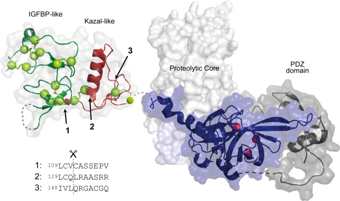
Figure 6.

Structural representation of HtrA1 with the indicated locations of the three primary N-termini generated by autolysis. The HtrA1 domain architecture is visualized by representation of the structures for the N-domain [Protein Data Bank (PDB) entry 3TJQ(30)], the trimeric proteolytic core (PDB entry 3NWU(29)), and the PDZ domain (PDB entry 2YTW(48)). Disulfide bridges are shown as yellow spheres, and the catalytic triad is shown as red spheres. The cut sites resulting in the three major autolytic forms are numbered from 1 to 3, and their position in the folded N-domain is indicated with arrows. The new N-termini were identified by Edman degradation, and the surrounding sequence for each cut site is shown below the structure. Cut sites 1 and 2 are the result of cleavages with cysteine at position P1.
