
Figure 2. Stages in voluntary head-restraint training.
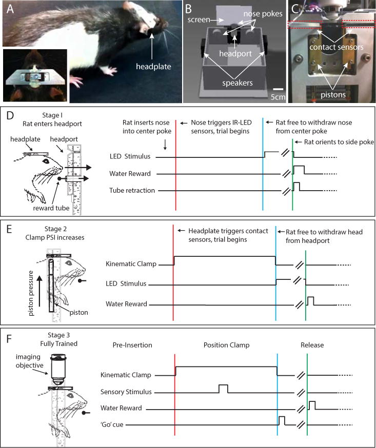
(A) Photograph of a rat that has been surgically implanted with the kinematic headplate. Inset: dorsal view of the headplate mounted on the rat’s head. (B) Illustration of an operant chamber used to train rats in voluntary head restraint. The chamber contains three nose pokes that can deliver water reward. Each nose poke also contains an infrared LED and sensor to detect insertion of the rat’s nose, and a visible LED to provide visual cues. To access the center nose poke, the animal must insert its head into the central headport that contains the mechanical registration system. The behavioral chamber also contains a back projection screen for the presentation of visual stimuli, as well as speakers mounted on the left and right chamber walls for auditory stimuli. (C) Photograph showing a rear view of the headport as installed in the wall of the behavioral chamber. Locations of the pistons are indicated by white arrows and positions of the arms of the contact sensors are indicated by white arrows and are surrounded by dashed red lines. (D–F) Illustration showing the stages in voluntary head restraint training. (D) Stage 1: During exploration of the behavioral chamber rats spontaneously insert their nose into the center nose poke, breaking an infrared beam, which triggers delivery of a water reward. Once the rat has learned to associate nose pokes with reward, on each successful trial, the center nose poke gradually moves further away from the center of the behavioral chamber. Left: Drawing indicating the movement of the center port further away from the animal. In order to continue to reach the reward, the rat must insert its head into an aperture in the headport while sliding its headplate further into the headplate slot. Right: Timing of events during a stage 1 behavioral trial. Stage 1 ends when the rat inserts its head far enough into the headport so that the leading edge of the headplate touches contact sensors in the headplate slot. (E) Stage 2: Rat acclimates to the kinematic clamp. Left: Drawing indicating the movement of the pistons during the beginning of the trial and the position of the rat head and headplate relative to the headport during restraint. Right: Timing of events during a stage 2 behavioral trial. Pistons are deployed when the contact sensors are activated (red line). Piston pressure is low and gradually increases over trials. The rat receives water reward after maintaining contact between the headplate and contact sensors in the headplate slot for a set duration. Withdrawal of the headplate from the slot before the end of the fixation period (blue line) leads to termination of the behavioral trial and a ‘time-out’ period when no water can be obtained. Right: (F) Stage 3. Once the rat has acclimated to full piston pressure and can maintain restraint for the desired duration, in vivo imaging can begin. Left: Drawing indicating the relative position of the rat head, headplate, imaging objective and headport. Right: Timing of events during a stage 3 behavioral trial. In this example, rats perform a two-alternative choice task in which the stimulus is presented during the head-fixation period.