Abstract
A mirror facet’s angle correction approach is presented for eliminating pupil plane distortions and sub-field image vignetting in the image mapping spectrometry (IMS). The two-axis light reflection problem on the image mapper is solved and a rigorous analytical solution is provided. The cellular fluorescence imaging experiment demonstrates that, with an angle-corrected image mapper, the acquired image quality of spectral channels has been significantly improved compared to previous IMS images. The proposed mathematical model can also be used in solving general two-axis beam steering problems for instruments with active optical mirrors.
Subject terms: spectral imaging, image mapping spectrometry, two-axis light reflection
1 Introduction
Image mapping spectrometry (IMS) is a novel snapshot spectral imaging technique that has been used in widespread applications, e.g., microscopy,1,2 endoscopy,3 ophthalmological imaging,4 brain imaging,5 and remote sensing.6 The operation of the IMS is based on the image mapping principle, which has been detailed elsewhere.2 Briefly, by utilizing a custom fabricated component-image mapper,7 the sample’s 3D (x, y, λ) datacube can be mapped to a 2D detector array for parallel measurement. Due to its snapshot advantage,8 the IMS features N-folds improvement in signal throughput when measuring N spectral sampling channels or spatial sampling points/lines compared to traditional scanning-based spectral imagers.9,10
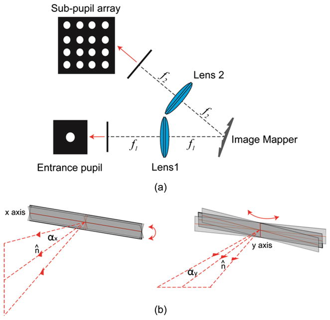
The core of the IMS is a 4-f imaging system with an image mapper located at the Fourier plane of entrance pupil [see Fig. 1(a)]. The image mapper consists of hundreds of mirror facets—each mirror facet is around 70 μm wide and fabricated with a 2D tilt angle (αx, αy) [see Fig. 1(b)]. The light reflected from a mirror facet has a 2D steering angle (βx, βy), and enters its associated sub-pupil at the exit plane of the 4-f system. The sub-pupils’ in-plane positions (x, y) are determined by the product of lens 2’s focal length f2 with the tangent of reflected light’s steering angle (βx, βy) [Fig. 1(a)]:
| (1) |
Fig. 1.
4-f optical system in the IMS. The image mapper is located at the Fourier plane of entrance pupil. Each mirror facet on the image mapper has a 2D tilt angle (αx, αy ) and reflects light towards directions along the x axis and y axis.
Since these sub-pupils are then imaged by an array of reimaging lenses which are evenly spaced, it is critical for each sub-pupil to be concentric with its associated reimaging lens. The accuracy of sub-pupil’s in-plane position thus determines the imaging performance of the system.
In our previous work,7 a mathematical model was proposed to simulate light reflection behavior on the image mapper. This theoretical model assumes that the light ray’s steering angles βx, βy reflected from a mirror facet are independent of each other and only related to the corresponding mirror facet’s tilt αx, αy by the relation:
| (2) |
This assumption is valid if the mirror facets’ tilt angles satisfy small angle approximation, and the image mapper has no overall tilts, i.e., the image mapper itself is perpendicular to the incident light. However, in a recently developed IMS system,3 the mirror facets’ maximal tilt angle reaches 0.075 radians and the image mapper has a 20 deg overall tilt with respect to the incident light. This fact makes the small angle approximation not valid anymore. And using the image mapper based on previous model causes two problems—pupil plane distortions and subfield image vignetting (see Sec. 2). To address this issue, we rigorously analyzed the light reflection behavior on the image mapper in 3D geometry and proposed a mirror facet’s angle correction approach. This correction approach successfully eliminates pupil plane distortions and sub-field image vignetting in the IMS and thus improves the image quality of acquired spectral channels.
The proposed light 3D reflection model has an advantage that it does not require small angle approximation (see Sec. 3). This feature is not only important for the IMS, but also important for instruments which require precise control of two-axis beam steering with active optical mirrors, e.g., astronomical image slicer11 and two-axis MEMS scanner.12 Due to its compact size and easy integration, the two-axis MEMS scanner is preferred in scanning display applications.12 However, it suffers pin cushion distortion due to the spherical projection onto a plane surface.13 By using the formula provided in Eqs. (8) and (9) (see Sec. 4), one can accurately predict the reflected light’s steering angles and calculate the correction coefficients for different tilt angle combinations along the two axes. This provides a potential simple solution for correcting pin cushion distortion in two-axis MEMS-scanner-based display applications.
2 Pupil Plane Distortions and Sub-Field Image Vignetting
At the exit plane of the IMS’ 4-f system, to be concentric with associated reimaging lens, the sub-pupil Pi,j is required to be located at
| (3) |
where Δd is the spacing between the centers of adjacent reimaging lenses, and m and n are number of columns and rows of reimaging lens array, respectively. By substituting x, y in Eq. (1) with xi, yj in Eq. (3), the required reflected light’s steering angles are
| (4) |
To calculate the required mirror facets’ tilt angles , previous model7 uses Eq. (2) and gives
| (5) |
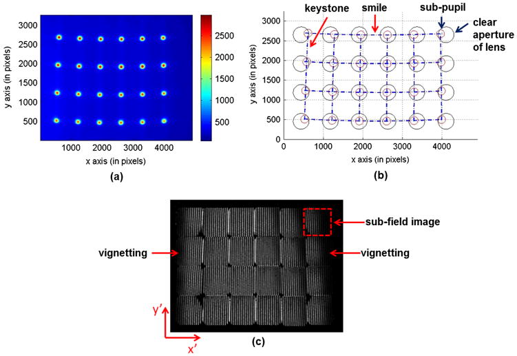
By using angles calculated with Eq. (5), an image mapper was fabricated to reflect light towards desired direction βx ∈ [±0.15, ±0.09, ±0.03] radians, βy ∈ [−0.09, −0.03] radians in an IMS.3 This image mapper was then tested in the IMS’ 4-f system with f1 = 165 mm and f2 = 90 mm. After 4-f transformation, the formed sub-pupil array at the exit plane was imaged by a monochromatic CCD camera (Imperx IPX-16M3-L, 4872 × 3248 pixels, pixel size: 7.4 μm) [see Fig. 2(a)]. To identify sub-pupil’s relative position on the pupil plane, the raw image was binarized with an intensity threshold and sub-pupils were then extracted and represented by red circles in Fig. 2(b). The blue dashed lines were drawn across the centers of these sub-pupils. Note that the horizontal dash lines are bent towards the center, while the vertical dash lines are tilted inwards. These two distortions correspond to “smile” and “keystone”, respectively,14 which shift sub-pupils away from their desired positions [the centers of black circles in Fig. 2(b)]. The shifted distance depends on the sub-pupil’s position with respect to the array’s center—the further a sub-pupil is away from the array’s center, the larger shift it has.
Fig. 2.
Pupil plane distortions and sub-field image vignetting. Due to the pupil plane distortions—“smile” and “keystone”, the sub-pupils [red circles in (b)] are shifted away from their desired positions, where the reimaging lenses are located [black circles in (b)]. Each sub-pupil has an associated sub-field image [dashed line square in (c)] at the back focal plane of reimaging lenses. The pupil plane distortions cause vignetting in sub-field images.
Since each sub-pupil’s associated reimaging lens has a clear aperture [black circles in Fig. 2(b)], the pupil plane distortions cause vignetting in the sub-pupil’s associated sub-field image. To show this effect, a uniform light field was imaged by the IMS and an image was captured at the focal plane of reimaging lenses [see Fig. 2(c)]. In an ideal case, each sub-field image should be equally bright. However, the results show that the edge sub-field images suffer severe spatial information loss due to image vignetting. Note that the edge sub-field images also show a shading effect from one side to another. This is due to the fact that in the IMS design3 the sub-pupils are located inside dispersive prisms which are 7.8 mm away from the reimaging lens’s aperture. This distance causes the un-uniform vignetting for different spatial positions in a sub-field.
3 Mirror Facet’s Tilt Angle Correction
The pupil plane distortions discussed in Sec. 2 are due to the fact that small angle approximation is not valid for large mirror facets’ tilts, i.e., Eq. (2) cannot accurately describe the relation between reflected light’s steering angle and corresponding mirror facet’s tilt angle. To solve this problem, we propose a light 3D reflection model which provides a rigorous analytical solution for the relation between mirror facet’s tilt angle (αx, αy) and reflected light’s steering angle (βx, βy).
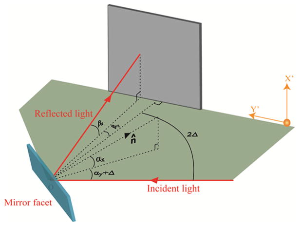
The light reflection behavior on a single mirror facet is shown in Fig. 3. Assuming the normal of the mirror facet has a 2D tilt angle (αx, αy)with respect to the image mapper, and the image mapper itself has an overall y tilt Δ with respect to the incident light direction. In the IMS, the following optical components are built with a folded optical axis that has a rotation angle 2Δ with respect to the incident light direction. And the reflected light from this mirror facet has a 2D steering angle (βx, βy) with respect to the folded optical axis. In order to get the trigonometric relation between (αx, αy) and (βx, βy), the incident light, reflected light and mirror facet’s normal direction are represented by unit vectors î, r̂ and n̂, respectively. Light reflection law gives:
| (6) |
where αi is the light incident angle with respect to the mirror facet’s normal. The first equation in Eq. (6) is based on the fact that the light incident angle is equal to the light reflected angle; while the second equation is based on the fact that the incident light, reflected light, and mirror facet’s normal are located at the same plane. In Eq. (6), by substituting the vectors î, r̂ and n̂ with their spatial coordinate components,
Fig. 3.
Light 3D reflection model on a mirror facet. The incident light, reflected light and the normal of mirror facet are located at the same plane. The image mapper has an overall y tilt Δ with respect to the incident light.
| (7) |
The relation between mirror facet’s tilt angle (αx, αy) and reflected light’s steering angle (βx, βy) can be analytically solved as
| (8) |
and the relation between light incident angle αi and mirror facet’s tilt angle (αx, αy) is
| (9) |
Equations (8) and (9) indicate that the light reflection behaviors along the two orthogonal directions are not independent, i.e., the reflected light’s steering angle (βx, βy) is a function of mirror facet’s both x and y tilts. Note that if the image mapper has no overall tilt (Δ = 0) and mirror facets’ tilts satisfy small angle approximation (αx ≪ 1, αy ≪ 1), Eq. (8) becomes Eq. (2). This fact indicates that Eq. (8) is a generalized form of Eq. (2) in solving two-axis light geometrical reflection problems.
For a given reflected light’s steering angle (βx, βy), by reversing Eq. (8) we can get the formula to calculate the required mirror facet’s tilt angle:
| (10) |
where
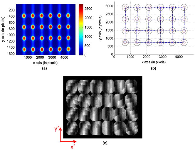
By employing derived relations in Eq. (10), we recalculated the required mirror facets’ tilt angles to reflect light towards direction βx ∈ [±0.15, ±0.09, ±0.03] radians, βy ∈ [±0.09, ±0.03] radians. The results are shown in Table 1. An image mapper was fabricated with these corrected angles. With this angle-corrected image mapper, the pupil plane and sub-field images were acquired in the same IMS system [see Fig. 4(a) and 4(c)]. The sub-pupils were extracted from the raw data and represented by red circles in Fig. 4(b). The results show that the pupil plane distortions and sub-field image vignetting have been greatly reduced by the proposed mirror facet’s angle correction approach.
Table 1.
Corrected versus original mirror facets’ tilt angles (αx, αy ) in radians.
| Original mirror facets’ tilt angles
| ||||||
|---|---|---|---|---|---|---|
| βx = 0.15 rad | βx = 0.09 rad | βx = 0.03 rad | βx = −0.03 rad | βx = −0.09 rad | βx = −0.15 rad | |
| βy = 0.09 rad | (0.0750, 0.0450) | (0.0450, 0.0450) | (0.0150, 0.0450) | (−0.0150, 0.0450) | (−0.0450, 0.0450) | (−0.0750, 0.0450) |
| βy = 0.03 rad | (0.0750, 0.0150) | (0.0450, 0.0150) | (0.0150, 0.0150) | (−0.0150, 0.0150) | (−0.0450, 0.0150) | (−0.0750, 0.0150) |
| βy = −0.03 rad | (0.0750, −0.0150) | (0.0450, −0.0150) | (0.0150, −0.0150) | (−0.0150, −0.0150) | (−0.0450, −0.0150) | (−0.0750, −0.0150) |
| βy = −0.09 rad | (0.0750, −0.0450) | (0.0450, −0.0450) | (0.0150, −0.0450) | (−0.0150, −0.0450) | (−0.0450,−0.0450) | (−0.0750, −0.0450) |
| Corrected mirror facets’ tilt angles | ||||||
|---|---|---|---|---|---|---|
| βx = 0.15 rad | βx = 0.09 rad | βx = 0.03 rad | βx = −0.03 rad | βx = −0.09 rad | βx = −0.15 rad | |
| βy = 0.09 rad | (0.0812, 0.0427) | (0.0487, 0.0442) | (0.0162, 0.0449) | (−0.0162, 0.0449) | (−0.0487, 0.0442) | (−0.0812, 0.0427) |
| βy = 0.03 rad | (0.0802, 0.0128) | (0.0482, 0.0142) | (0.0161, 0.0149) | (−0.0161, 0.0149) | (−0.0482, 0.0142) | (−0.0802, 0.0128) |
| βy = −0.03 rad | (0.0794, −0.0170) | (0.0476, −0.0157) | (0.0159, −0.0151) | (−0.0159, −0.0151) | (−0.0476, −0.0157) | (−0.0794, −0.0170) |
| βy = −0.09 rad | (0.0786, −0.0468) | (0.0472, −0.0456) | (0.0157, −0.0451) | (−0.0157, −0.0451) | (−0.0472, −0.0456) | (−0.0786, −0.0468) |
Fig. 4.
Pupil plane image and sub-field image with an angle-corrected image mapper in the IMS.
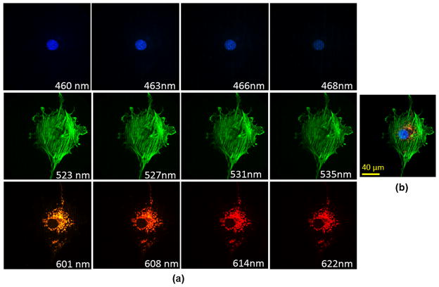
Additionally, to show the imaging performance of the IMS with an angle-corrected image mapper, a triple-labeled bovine pulmonary artery endothelial cell was imaged. The cell mitochondria were labeled with MitoTracker Red; filamentous actin was labeled with Alexa Fluor 488; and nuclei were labeled with DAPI. The IMS was coupled to a side image port of a Zeiss inverted microscope (Axio Observer A1) and functioned as a spectral imager, and the sample was imaged by a Zeiss 63×, NA = 1.4 Plan-Apochromat objective on the microscope with 0.5 sec integration time. Selected spectral channel images and panchromatic display of acquired datacube are shown in Fig. 5(a) and 5(b), respectively. Compared to images acquired by previous IMS,2,3 the image quality of spectral channels has been significantly improved.
Fig. 5.
Hyperspectral fluorescence imaging of triple-labeled bovine pulmonary artery endothelial cells. The cell nucleus is labeled with DAPI; filamentous actin is labeled with Alexa Fluor 488; and mitochondria are labeled with MitoTracker Red. (a) Selected spectral channel images. (b) Panchromatic display of acquired datacube.
4 Conclusions
In summary, we have presented a mirror facet’s tilt angle correction approach to eliminate the pupil plane distortions and sub-field image vignetting in the IMS. A rigorous mathematical model with an analytical solution is proposed to describe light reflection behavior on the image mapper. The imaging results demonstrate that, with an angle-corrected image mapper, the image quality of acquired spectral channels has been significantly improved compared to previous IMS images.
Acknowledgments
This work is supported by the National Institute of Health under Grant No. R21EB009186.
Biographies
 Liang Gao received his BS degree in physics at Tsinghua University in 2005 and his PhD degree in applied physics at Rice University in 2011. He is currently a postdoctoral research associate in bioengineering at Rice University, Houston, Texas, in the laboratory of Tomasz Tkaczyk. His research interests include microscopy, optical design and fabrication, and biomedical imaging.
 Tomasz S. Tkaczyk is an assistant professor of bioengineering and electrical and computer engineering at Rice University, Houston, Texas, where he develops modern optical instrumentation for biological and medical applications. His primary research is in microscopy, including endomicroscopy, cost-effective high-performance optics for diagnostics, and multidimensional imaging (snapshot hyperspectral microscopy and spectropolarimetry). He received his MS and PhD degrees from the Institute of Micromechanics and Photonics, department of Mechatronics, Warsaw University of Technology, Poland. Beginning in 2003, after his postdoctoral training, he worked as a research professor at the College of Optical Sciences, University of Arizona. He joined Rice University in the summer of 2007.
Contributor Information
Liang Gao, Email: ttkaczyk@rice.edu, Rice University, Department of Bioengineering, MS 142, 6100 Main Street, Houston, Texas 77005.
Tomasz S. Tkaczyk, Rice University, Department of Bioengineering, Department of Electrical and Computer Engineering, MS 142, 6100 Main Street, Houston, Texas 77005
References
- 1.Gao L, Kester RT, Tkaczyk TS. Compact image slicing spectrometer (ISS) for hyperspectral fluorescence microscopy. Opt Express. 2009;17(15):12293–12308. doi: 10.1364/oe.17.012293. [DOI] [PMC free article] [PubMed] [Google Scholar]
- 2.Gao L, et al. Snapshot image mapping spectrometer (IMS) with high sampling density for hyperspectral microscopy. Opt Express. 2010;18(14):14330–14344. doi: 10.1364/OE.18.014330. [DOI] [PMC free article] [PubMed] [Google Scholar]
- 3.Kester RT, et al. Real-time snapshot hyperspectral imaging endoscope. J Biomed Opt. 2011;16(5):056005. doi: 10.1117/1.3574756. [DOI] [PMC free article] [PubMed] [Google Scholar]
- 4.Gao L, Smith RT, Tkaczyk TS. Snapshot hyperspectral retinal camera with the image mapping spectrometer (IMS) Biomed Opt Express. 2012;3(1):48–54. doi: 10.1364/BOE.3.000048. [DOI] [PMC free article] [PubMed] [Google Scholar]
- 5.Hagen N. Spectrally-resolved imaging of dynamic turbid media. Proc SPIE. 2011;7892(1):789206. [Google Scholar]
- 6.Kester R. Image mapping spectrometry: a novel hyperspectral platform for rapid snapshot imaging. Proc SPIE. 2011;8048(1):80480J. [Google Scholar]
- 7.Kester RT, Gao L, Tkaczyk TS. Development of image mappers for hyperspectral biomedical imaging applications. Appl Optics. 2010;49(10):1886–1899. doi: 10.1364/AO.49.001886. [DOI] [PMC free article] [PubMed] [Google Scholar]
- 8.Nathan H, et al. The snapshot advantage: a review of the improvement in light collection for parallel high-D measurement systems. doi: 10.1117/1.OE.51.11.111702. in press. [DOI] [PMC free article] [PubMed] [Google Scholar]
- 9.Morris HR, Hoyt CC, Treado PJ. Imaging spectrometers for fluorescence and raman microscopy-acoustooptic and liquid-crystal tunable filters. Appl Spectrosc. 1994;48(7):857–866. [Google Scholar]
- 10.Sinclair MB, et al. Hyperspectral confocal microscope. Appl Opt. 2006;45(24):6283–6291. doi: 10.1364/ao.45.006283. [DOI] [PubMed] [Google Scholar]
- 11.Vives S, Prieto E. Original image slicer designed for integral field spectroscopy with the near-infrared spectrograph for the James Webb Space Telescope. Opt Eng. 2006;45(9):093001. [Google Scholar]
- 12.Yalcinkaya AD, et al. Two-axis electromagnetic microscanner for high resolution displays. J Microelectromech Syst. 2006;15(4):786–794. [Google Scholar]
- 13.Li Y. Beam deflection and scanning by two-mirror and two-axis systems of different architectures: a unified approach. Appl Opt. 2008;47(32):5976–5985. doi: 10.1364/ao.47.005976. [DOI] [PubMed] [Google Scholar]
- 14.Mouroulis PZ. Spectral and spatial uniformity in pushbroom imaging spectrometers. Proc SPIE. 1999;3753:133–141. [Google Scholar]


