Abstract
Custom implants for the reconstruction of craniofacial defects have gained importance due to better performance over their generic counterparts. This is due to the precise adaptation to the region of implantation, reduced surgical times and better cosmesis. Application of 3D modeling in craniofacial surgery is changing the way surgeons are planning surgeries and graphic designers are designing custom implants. Advances in manufacturing processes and ushering of additive manufacturing for direct production of implants has eliminated the constraints of shape, size and internal structure and mechanical properties making it possible for the fabrication of implants that conform to the physical and mechanical requirements of the region of implantation. This article will review recent trends in 3D modeling and custom implants in craniofacial reconstruction.
Keywords: 3D modeling, implants, additive manufacturing, craniofacial surgery, porous titanium, PEEK implants, electron beam melting, patient specific implants, custom implants, CAD CAM surgery, CAD CAM implants
INTRODUCTION
Reconstruction of the craniofacial skeleton is extremely challenging even to the most experienced surgeon. Some of the critical factors that contribute to the complexity include anatomy, presence of vital structures adjacent to the affected part, uniqueness of each defect and chances of infection. In any craniofacial reconstruction whether secondary to trauma, ablative tumor resection, infection and congenital/developmental deformities, restoration of aesthetics and function is the primary goal and calls for precise pre-surgical planning and execution of the plan. Auto grafts are the gold standard for craniofacial skeletal reconstruction. However their use is limited by the availability of suitable donor site especially for large defects, additional expensive surgeries, tissue harvesting problems, donor site morbidity with an additional patient discomfort, chances of infection at both the recipient and donor sites, increased surgical time, resorption of the graft requiring secondary surgeries and the need for additionally skilled surgical team, which has led to the search of alloplastic material that would be suitable without the inherent problems.[1,2,3,4,5,6] Craniofacial defects also have complex anatomical shapes that is hard to achieve intraoperatively by carving harvested bone from the donor site. Hence it would be very useful for the surgeon to be aided by standard practice and proven methods in engineering wherein, the design and performance of the reconstructed implants/prosthesis can be predicted with accuracy and precision.
Surgeons have adapted to enhanced visualization techniques for close to two decades and even today this is an advancing field. Advantages of virtual reality can be totally beneficial only when transferred to the clinical scenario, i.e., the operatory to achieve expected results. Development of computer assisted design (CAD) and computer assisted manufacturing (CAM) systems that adapt to the surgeons needs has resulted in a gamut of the armamentarium for computer assisted surgery. Such systems specifically focus on enhanced visualization tools – 3D modeling or better termed as virtual reality and gives the surgeon the ability for precise preoperative planning and perform virtual osteotomies resections and design patient specific implants preoperatively. These virtual models can be imported into an intraoperative navigation system for precise placement of bone segments, implants and hardware. Advances in manufacturing technology and material science has led to the possibility of turning such virtual model or design into reality as physical replica models, surgical guides or cutting jigs or splints for intraoperative use and patient specific implants.
The success and longevity of implants depend upon factors like material characteristics, design of the implant and the surgeon's skill. Advances in image processing and manufacturing technologies have made it possible for the surgeons to have hand held models for a tactile perception of the defect. The next level of automation has brought in fabrication of custom designed implants as the best option for reconstruction of craniofacial defects. Custom implants for the reconstruction of craniofacial defects have recently gained importance due to their better performance over their generic counterparts. This is attributed to, the precise adaptation to the region of implantation, that reduces surgical times, in turn leading to lesser chances for infection, faster recovery and better cosmesis in craniofacial surgery.[7,8,9]
Enhancements in recent years have been in the area of design, materials and manufacturing process for craniofacial implants. Use of the haptic device introduced a decade ago, and 3D visualization has given the graphic designer the capability to design these implants more aesthetically enhancing the cosmetic outcome of custom implants. Availability of multitude materials as, autologous bone flaps, titanium, polymethylmethacrylate (PMMA), bioceramics as hydroxyapatite (HA), polyethylene, biodegradable polymers that have been used for craniofacial reconstruction give the surgeon many options to choose from. Recent introduction of direct digital manufacturing technologies that enable the fabrication of porous implants with lattice and solid structures in one go from patient specific data has opened up a new horizon for the next generation of craniofacial implants.
CAD/CAM systems have enabled us the ability to design and manufacture custom implants at an acceptable cost in a reasonable time. Additive manufacturing technologies as stereolithography (SLA), polyjet, fused deposition modeling; 3D printing, selective laser melting (SLM), selective laser sintering (SLS) and electron beam melting (EBM) lend themselves to manufacturing of complex anatomic parts without any barriers of design constraints including lattice structures. SLS, SLM and EBM use biocompatible implantable materials as titanium, Ti6Al4V, chrome cobalt and polyetheretherketone (PEEK) and facilitate the direct production of implants with engineered properties that match properties of the tissues at the region of implantation. Surgeons can now have access to the facilities service providers.
THE PROCESS FLOW
The complete process flow for CAD/CAM generated implants is shown in Figure 1 and is described briefly below.
Figure 1.
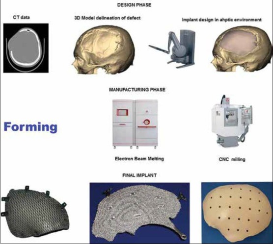
Process flow for design and manufacture of computer assisted design/computer assisted manufacturing generated implants
The process generally known as reverse engineering in the engineering world starts with acquiring computed tomography (CT)/magnetic resonance imaging 2D image data as digital imaging and communications in medicine (DICOM) files. The DICOM data is then processed using software as MIMICS, Biobuild, 3D Doctor to name some to create a 3D model of the anatomy depicting the defect. The 3D model file is then imported into design software which could be either a haptic based environment as Freeform® Geomagic or CAD based one as 3 Matic™ from materialize to create the final implant design. The implant is then manufactured by machining a block of material (subtractive manufacturing) or by adding material layer by layer and fusion of the layers (additive manufacturing).
The process of 3D modeling and custom implants is continuously evolving with advancements in the design and manufacturing worlds. This article will review the recent literature on 3D Modeling and recent advances in custom implants in cranial, skull base, zygomatic orbital, midface, mandible reconstruction, orthognathic surgery and treatment of the syndromized patient more specifically in relation to application of CAD/CAM technologies craniofacial reconstruction with respect to various materials and also include the author's 15 years’ experience in 3D modeling and design and manufacturing of custom implants and discuss future perspectives. A systematic search on National Library of Medicine (PubMed/Medlinehttp://www.ncbi.nlm.nih.gov/pubmed) for related articles with search criteria as 3D modeling, custom craniofacial implants, orbital implants, CAD/CAM craniofacial applications and computer assisted craniofacial surgery was performed. Articles related to 3D modeling, custom/patient specific implants in craniofacial surgery using various materials were chosen for review.
CAD/CAM in cranioplasty
Cranioplasty is the procedure of choice for treating cranial defects commonly caused by trauma, tumor removal or decompressive craniotomies. The main goal of cranioplasty is to protect the brain and alleviate psychological affliction caused by the defect and enhance social performance of the patients. Hence the ideal cranial implant material would fit the cranial defect and achieve complete closure, be, radiolucent – for postoperative imaging, resistant to infections, strong to biomechanical processes, easy to shape, not expensive and ready to use. The following paragraphs highlight the advantages of 3D modeling and custom implant manufacturing in cranioplasty that allows the surgeon to use the material of his choice.
Titanium
Titanium has been a material of choice for cranioplasty due to its biocompatibility, strength to weight ratio and osseo integrative property. Titanium in various forms as sheets, mesh have been in use for sometime more recently with the advent of EBM or direct metal laser sintering (DMLS) 3D printed cranial implants has come into vogue.
Titanium mesh reconstruction is a popular method among the surgeons due to the ability to use the preformed mesh as a template for resection. However, the strength of a thin dynamic mesh that can be molded intraoperatively at times requires to be enhanced with PMMA.
In recent years the model of the cranium with the defect is fabricated using 3D printing technologies and used as a replica or template of the actual region of interest depicting the precise defect. A secondary processing method as forming is used to produce the actual implant.[6,10] This process delivers a well-fitting prosthesis and is very useful in treating large cranial defects with advantages of reduced, operating time, healing time and hospitalization period, eventually leading to reduced cost to the patient. However, the process involves fabrication of the rapid prototyping (RP) model at an additional cost and time. Figure 2 shows a large titanium mesh cranioplasty implant and the same being fitted in surgery.
Figure 2.
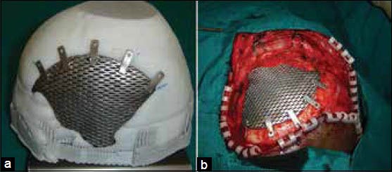
(a) Titanium mesh implant fitted to the cranium model, (b) Intraoperative fixation of implant
The technology was used to assess the temporalis thickness and include in the design of the implant for achieving best cosmetic results and prevent the “hourglass facial deformity.”[11]
A long-term (6-12 years) evaluation of CAD/CAM titanium cranioplasty of 26 patients with large cranial defects on a visual analog scale showed that none of the implants required removal, and all patients would have chosen cranioplasty again and had stated improvement in their life-style. However the authors observed sub optimal follow-up imaging in four patients with meningioma. The authors concluded titanium to be material of choice for secondary reconstruction of large cranial defects resulting from decompressive craniectomies following trauma or infarction.[12] PMMA would be the choice for primary reconstruction when monitoring with postoperative imaging is needed. The technology has also been used as a one-step procedure for resection and reconstruction of skull base meningioma wherein, the authors used the preformed titanium plate as a template for resecting the cranium.[13]
In the very recent past ushering ushering of metal additive in manufacturing EBM and DMLS has introduced the direct fabrication of the implant without the need for the template. This next gen implants will aim to confirm to the normalized shape of the part it replaces, with mechanical properties being close to that of the region of implantation preventing stress shielding in load bearing regions, porous for bone ingrowth, have repeatable properties.[14,15,16,17,18,19,20,21,22,23,24]
As mentioned earlier, a 3D digital model of the cranium is generated from the CT data. The virtual model is then used to create the implant design either by mirroring from the contralateral side or by generating curves based on the anatomical region with CAD based/haptic devices. The implant model is then sent to the EBM machine from ARCAM AB® or DMLS from electro optical systems (EOS) GmbH EOS. The software then creates layers of 2D images that are sent to the machine for solidification of the part from a bed of Ti6AlV4 powder layer by layer that finally creates an implant ready for implantation. EBM and DMLS technologies alleviate the need for a skull model or a secondary process to create a custom implant. Figure 3 shows a patient specific porous titanium implant made using EBM and the same fitting to the model and intraoperative fixation of the implant.
Figure 3.
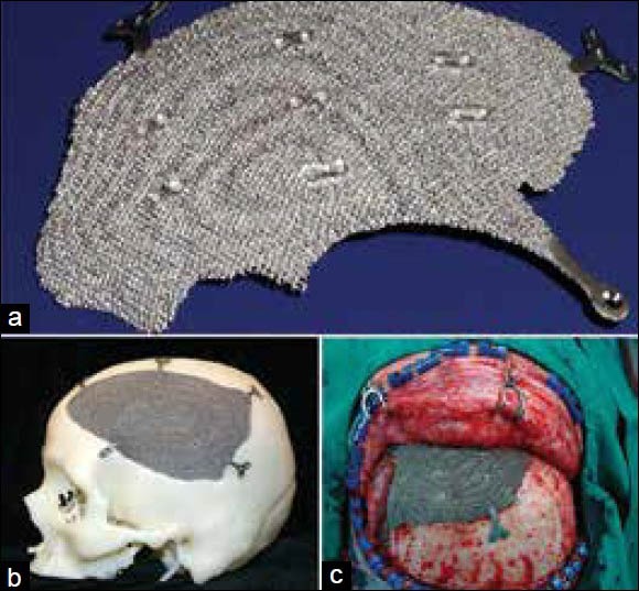
(a) Patient specific porous titanium implant made using electron beam melting, (b) Implant fitting to the cranium model, (c) Intraoperative fixation of implant
PMMA, bioceramics and other polymers
CAD/CAM technology has been used successfully to make PMMA implants as well. 3D models of cranial implants were designed from CT scan DICOM data and 3D printing technology is used to produce mold templates of the proposed implant, which was then used intraoperatively to quickly make the implant in the operatory.[25] Similarly, CT scan data was used to create an implant digital model and RP to produce silicon molds which were then used for creating patient specific cranial implant.[26] The authors concluded that custom-made implants for cranioplasty showed a significant improvement in morphology especially for repairing large and complex-shaped cranial defects. The authors further concluded technique may be useful for the bone reconstruction of other sites as well. Custom implants from polypropylene and polyester were made using a computerized numerical control (CNC) milled 3D model of the skull generated from CT scan data.[27] Stereolithographic or 3D printed models of skull defects generated from CT scan can be used as templates to fabricate porous bioceramic Hydroxy Apatite implants. 60 patients received these implants and were followed-up for 2 years.[28] Similar implants were designed in CAD with and manufactured using the SLA photo polymerization process. The material used was a combination of resin and HA powder. The final implant seen in Figure 4 had surface porosity for tissue ingrowth.[29]
Figure 4.
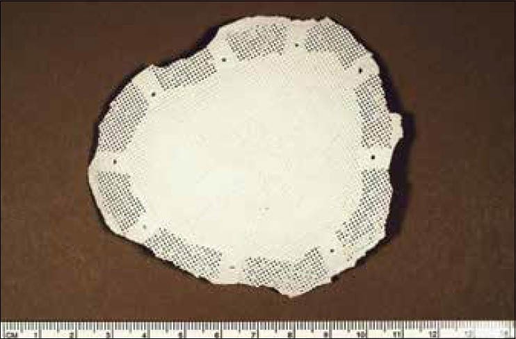
Porous resin and hydroxyapatite implant manufactured by stereolithography
PEEK cranial implants
PEEK custom cranial implants are being used more in the current times.[30,31] PEEK is a highly strong engineering thermoplastic, which retains its chemical and mechanical properties even at high temperatures. The material has high biocompatibility and biostability maintaining its physical and chemical characteristics on long-term exposure to body fluids. The modulus of elasticity of PEEK is similar to that of cortical bone, preventing any stress shielding making it a better choice over metallic implants that have high modulus of elasticity. PEEK is also radiolucent facilitating postoperative imaging procedures. Implants can be designed to replace exact anatomy even in bulky regions as the material is very light. The material can be repeatedly sterilized by common methods as autoclave, gamma or ethylene oxide. PEEK lends itself to machining of complex organic shapes very well. PEEK implants can be fixated to the adjacent bone with standard screws and plates of surgeons’ choice. All the above mentioned characteristics have made PEEK the sought after material for cranial implants by manufacturers and surgeons in the recent past. In general, PEEK implants are made from a block of extruded material using a CNC machining. Figure 5a–c shows images of machined PEEK implant and the same being fixed to the cranium in surgery and postoperative X-ray imaging. PEEK implants can be used in non-load bearing regions of the craniofacial skeleton. PEEK can also be sintered to produce implants similar to the machined PEEK.[32] CAD designed PEEK custom implants have been used to correct cranial, frontal, malar and mandibular defects.[33,34]
Figure 5.
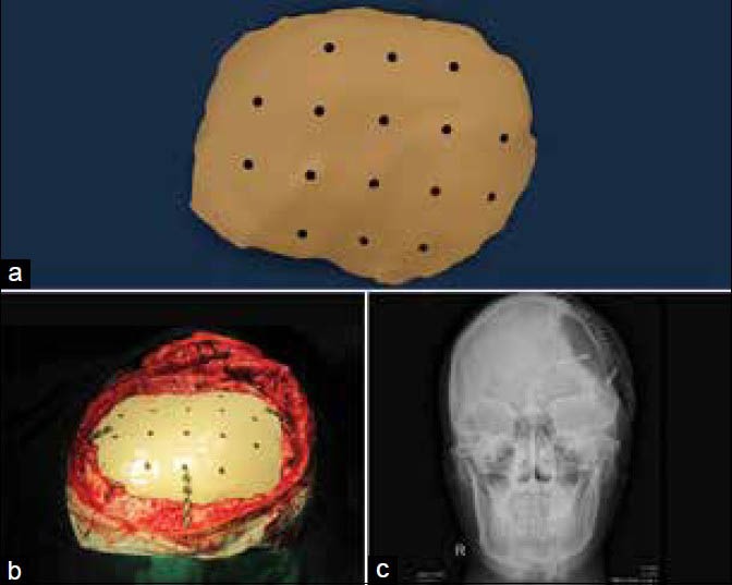
(a) Machined polyetheretherketone implant, (b) Intraoperative fixation to the cranium, (c) Postoperative X-ray imaging
CAD/CAM in mandible reconstruction
The ultimate goal of mandibular reconstruction is to restore speech, masticatory function and facial form. Current reconstruction procedures combine mandible reconstruction plate fixation and use of micro vascular flaps.
Virtual pre bending of mandible recon plates
Intraoperative bending of plates can be time consuming. Bending reconstruction plates depends on the complexity of resection and surgeon's skill. Bending the plates on the 3D models fabricated using additive manufacturing technologies prior to the surgery reduces operating times. Some authors[35] have found saving of an average of 0.4 hr while others[36] in a study of 30 patients reported a 1.4 hrs reduction of operating times. Ideal positioning of mandibular segments, time saving by no intraoperative repeated bending and adapting of plates, use of the original surface of the cortical bone as a template for adapting the recon plate, facilitating the preoperative surgical simulation and restoration of centric occlusion of the patient were some of the benefits of virtual surgical planning and construction.[37,38] In a study, wherein five oral and maxilla facial surgeons adapted a standard 10-hole Compact UniLock 2.4-mm large plates (Synthes) on stereolithographic models and virtual bending was done by importing and bending polygonal model of the same plate into standard CAD/CAM software, the author found statistically significant better adaptation of the virtual model compared with the physical model which favors manufacturing of patient specific pre bent plates.[39] The above studies concur with the previous observation of preoperative bending of plates may result in lesser bending stresses and may reduce the chances of postoperative plate breakage reported.[40] Computer aided planning simulated the surgical resection and laser sintered model derived from the plan and CT data for pre bending the reconstruction plate has been successfully used by some authors [Figure 6].[41]
Figure 6.
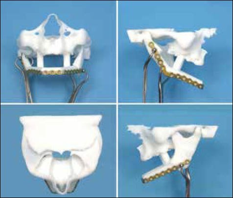
Virtual surgical planning and manufacturing of the guides for mandible reconstruction
Virtual surgical planning for mandible reconstruction and micro vascular bone tissue grafting
Micro vascular bone tissue grafting for mid facial and mandible reconstruction has improved over years and gives the surgeon a new outlook in reconstruction of large craniofacial defects. Placement of dental implants on the revascularized grafts has made the procedure very attractive to surgeons and patients as well. However the large variety of donor sites, shape and complexity of the facial skeleton, harvesting the exact shape, precise positioning of the grafts are some of the pertinent problems that make traditional planning methods challenging even for the experienced surgeon. Added to the complexity many procedures involve a combination of custom implants and micro vascular osteocutaneous flaps for best results. Computer assisted planning techniques and guides generated out of the process go a long way in assisting the surgeon in achieving facial symmetry, preventing dystopia and implant based dental rehabilitation comfortably with reduced operating time and lesser chances for repeat surgeries. For mid facial reconstruction custom implants would be the preferred method and for the mandible the traditional recon plates can be used.
Process flow for virtual surgical planning and manufacturing of the guides is shown in Figure 7a–e. The process starts with 3D reconstruction of both the donor (fibula, scapula etc as the case may be) and recipient site maxilla/mandible. Virtual 3D models are generated depicting the pathological region in the recipient region and the vasculature in the donor region. The part to be resected is then determined and the part to be harvested is designed accordingly. Resection and harvesting guides are then designed taking the surgical needs like access to the operative site and vasculature reconstruction. The guide is then produced with 3D printing methods using a biocompatible material approved for the purpose that can be used in surgery for resection of the recipient site and harvesting the flap from the donor site. The guide is a 3D printed part and is generated in accordance to the resection/harvesting postoperative plan of the craniofacial skeletal structures and the donor site. The postoperative plan mandible model is used to adapt the recon plate. The surgeon then uses the guide on the harvested fibula and precisely cuts the segments for reconstruction. The surgical planning is performed planned over the internet and teleconsultations gives access to technology and expertise of surgeons all over the globe even in remote locations.
Figure 7.
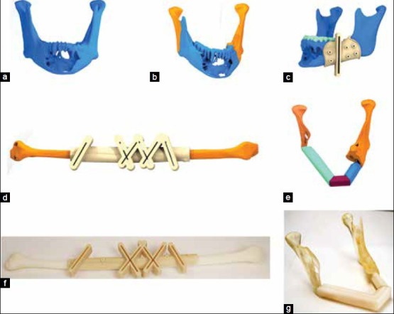
(a-e) Process plan for virtual surgical planning for fibula reconstruction of mandible (f) Fibula guide fitting to fibula bone model and (g) post op reconstructed mandible bone mode
Virtual surgical planning with 3D models using preoperative CT data enables the use of the outer surface contour of the un operated mandible as a reference for positioning the plate if there is no expansion of the buccal plates. Cutting guides can be very precisely designed and made with biocompatible materials for intraoperative use for tumor resection as well as harvesting of fibula segments. Fibula segments harvested using such jigs is found to be repositioned in the mandible very precisely with minimal adjustments if necessary and are very useful in extensive mandible reconstructions where the maxillary mandible relation is completely lost in all 3 directions. A mathematical algorithm to derive an optimal position for bone grafting from the iliac crest for reconstruction of large mandible resection defects had also been made for teleconsultations of experts between Vienna and Switzerland and established the possibility of using the technology on a global basis.[42]
The world's first additive manufactured full mandible was implanted in a patient by Dr. Jules Poukens and his team in Belgium is seen in [Figure 8].[43]
Figure 8.
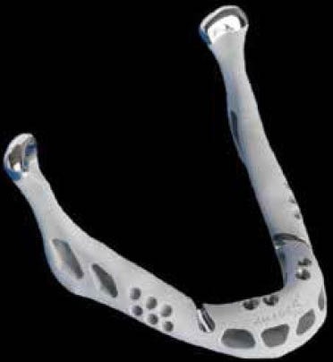
3D printed titanium mandible implant
Reducing operating time is one of the key prognostic factors in free flap surgery. In addition, reduced blood loss, chances of postoperative infection[44] and perioperative cost are some other benefits of virtual surgical planning and cutting guides.[45] A new protocol for mandible for design and manufacture of custom cutting guides for complete ablative tumor resection of the mandible including the condyles has been described.[46] The surgical device consisted of two components a cutting guide and a titanium reconstructive bone plate and was designed as a patient specific device from the patients CT scan data. The cutting guides assisted precisely to transfer the virtually planned osteotomies to the surgical scenario. The bone plate was designed using the patient's anatomical data including the condyles. The authors found a reduction of operating time.
Restoration of masticatory function is very dependent on the basal bone position and relationship of the maxilla and mandible. To achieve a good anatomic contour and optimal placement of the flap for prosthetic rehabilitation the need for precise computer assisted planning, pre and postoperative simulation 3D models cannot be over emphasized. The use of stereolithographic models for planning complex maxilla and mandibular reconstruction and generation of surgical guides has been emphasized.
Patient specific dental implants for atrophic bone
In atrophic mandible standard diameter root form implants are a challenge and bone reconstructive surgery may not be the treatment of choice due to patient acceptance or other contraindications. In a 2 year study of five patients with severe posterior atrophy of mandible custom designed blade implants made using CAD/CAM technologies manufactured using RP technology – SLS were successfully placed. Subsequently, prosthesis was also constructed successfully and no rejection, infection or failure of the treatment was seen.[47] This opens-up a whole new concept for dental implant design and prosthetic reconstruction.
Construction of arch forms or space holders for grafts
3D printed model can be used to adapt arch forms or titanium space holders for bone grafts to be held in position until integration with the host bone takes place.[48] 3D models are reconstructed from the CT scan data. The defective region is ascertained and a surgical resection is planned. An ideal arch form is then constructed considering the shape and position of implants to achieve a good occlusion. A 3D printed model is then fabricated that forms a template for adapting the titanium mesh which will be used as the space holder. Figures 9 and 10 show a 3D reconstruction of a maxilla and mandible and the arch form reconstruction that was used as a space holder.
Figure 9.

3D reconstruction of a mandible tumor and arch form reconstruction for adaptation of titanium mesh as graft space holder
Figure 10.

3D reconstruction of a maxillary bone and arch form reconstruction for adaptation of titanium mesh as graft space holder
Midface reconstruction
Midface reconstruction after extensive ablative tumor resection often, extends to the regions from the orbit to the alveolar bone, involves the nasal bone medially and may be unilateral and bilateral. The defects themselves have been classified as Class I-IV according to extension of the pathology.[49] The authors further also state there is no single flap procedure that can provide a solution for larger Class III defects. Smaller defects involving only the alveolar ridge can be corrected using ridge form plates and bone grafting, but larger defects require a combination of procedures as osteocutaneous flaps and patient specific implants that makes it more difficult to visualize the outcome. In order to achieve the best cosmetic and functional outcome some critical considerations for treatment of larger defects of the midface include soft-tissue reconstruction, establishment of connection between the residual alveolar bone and the zygomatic buttress, orbito-zygomatic complex reconstruction and alveolar ridge reconstruction for dental implant placement. Computer assisted 3D modeling and virtual surgical planning can give the surgeon a better understanding of the anatomy, osteotomies of the donor and recipient sites and planning of patient specific implants help precise placement of the bone graft in an optimum position for dental rehabilitation. Reconstruction of the orbital wall by mirroring data from the normal side has been described by several authors.[50,51,52,53] A methodology for computer assisted surgical planning and custom titanium plates and mesh for midfacial reconstruction. 3D printed models have been used as a template to presurgically adapt a titanium mesh or plate to precisely fit the defects of the orbital wall a procedure that helps to reduce surgical time.[54,55] Stereolithographic models fabricated from patient's CT have been used to reshape a sheet of titanium for creating patient specific implants for orbital floor reconstruction.[56] CAD design for the implant was derived from the CT scan data and orbital implants were machined in bio ceramic glass material (Bioverit II).[57] A similar design process was used and an implant was made from external hexagon compound an artificial bone like material approved by Food and Drug Administration of China.[58] A combination of CT scan data, virtual surgical planning and custom titanium implants and micro vascular flap reconstruction was used for treatment of an extensive maxillary resection extending from the orbital floor to the alveolus. Dental implant placement was also determined in the virtual surgical planning. The defective region was imaged and data from the contralateral side was mirrored with reference to the mid sagittal plane for correction of the defect. The scapula was used as the donor site and an optimized location for the graft that would satisfy the design of the alveolar reconstruction was determined with virtual surgical planning. The authors mention osteomyocutaneous flap and the titanium implant design were separated by virtue of the outlines. The titanium implant supporting the midfacial region was then fabricated. The titanium implant and the flap were fixated to the basal bone using traditional plates and screws. The scapula flap was then positioned in the predetermined optimum location for placement of dental implants. The dental implants were then placed later as a secondary procedure. Manufacturing the implants and designing the scapula flap is a major part of the process and the complete success depends on placing the implant and the graft in the predetermined 3dimensional location. Precise placement can be achieved with intraoperative navigational systems. The titanium implant in this case replaced the zygomatic bone and arch and the orbital walls in a close to original shape [Figure 11].[59]
Figure 11.
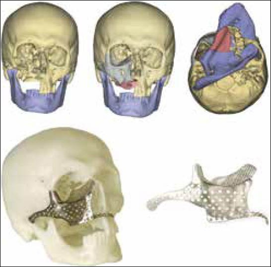
Maxillary defect reconstruction and the use of a titanium mesh as a temporary space holder for the graft[59]
Maxillo mandibular impressions were taken with trial dentures and articulated to arrive at a precise dental implant placement to achieve correct occlusion and guides for fibula resection and dental implant placement was constructed. The guides were used for fibula resection and placement of dental implants. Postoperative stable functional occlusion and good aesthetics were achieved. The authors concluded “the incorporation of CAD-CAM technologies to this field has enabled the refinement of both the surgical and prosthetic phases through a holistic 3D evaluation of the target defect, simulation of the surgical reconstruction and prosthetic rehabilitation and effective transfer of the preoperative plan to the operating room.” The authors further, impact on clinical outcome and ultimately patients’ quality-of-life should favor the implementation and further development of this technology despite the additional cost [Figure 12].[60]
Figure 12.
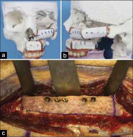
(a and b) Midface reconstruction plan with fibula graft, (c) Dental implants placement in the fibula flap
Corrective surgery and implant combined procedures
In some cases, a combination of custom implants and other corrective surgical procedures as fixation of salvageable large chunks of fractured bone as in blown out midfacial fractures are performed to restore the facial structure. Figure 13 shows correction of a blown out maxillary fracture by repositioning and fixation of some of the large bone pieces and a PEEK custom implant. A bigger implant was made and modified in surgery as per requirements. This allowed the surgeon to use autologous bone to the maximum possible extent and limit the use of alloplastic material to the minimal extent required. The ease of modification of the implant intraoperatively allows the surgeon to make the final decision in surgery.
Figure 13.
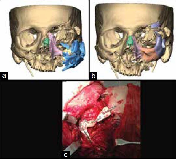
(a) Reconstructed blown out maxillary fracture, (b) Repositioning and fixation of some of the large bone segments, (c) Intraoperative fixation of polyetheretherketone implant
Similarly orthognathic surgery can be used to reposition the maxilla/mandible and structural differences between the right and left sides can be corrected using custom implants made of PEEK or silicone material.
Craniofacial reconstruction of the syndromic patient
The syndromic patient exhibits multiple distinctive facial characteristics as hypertelorism, frontal bossing, midfacial hypo/hyperplasia, malar and zygomatic region abnormalities and micrognathia to name a few. 3D modeling and custom implants would be very helpful to the surgeon in reconstruction of such multiple abnormalities that co-exist specifically due to the fact that multiple surgeries have to be performed over time and combination of bone grafts from regions of the body and patient specific implants would be required to restore near normal esthetics and functions in a growing individual. Surgical guides for resection and templates are very useful tools for the reconstructive surgeon. Establishment of morphometric data for the hard and soft-tissues of various regions of the face like the zygomatic arch, nose, malar, mandible angle, symphysis and contour and pre surgical simulation can go a long way in precise designing of the template and guides for resection.
Successful reconstruction of the hypo plastic zygomatic and orbital region in treacher collins syndrome (TCS) using normative morphometric data derived from computer generated 3D models has been reported.[61] Four patients with TCS in the ages of 6, 10, 14 and 20 were chosen for tomodensitometric studies. 40 controls who underwent CT scan for reasons unrelated to facial skeleton were chosen. In total 8 TCS and 80 control orbital and zygomatic volumes were derived for comparison. Ideal zygoma for the patient was then chosen by computer simulation. Cutting guides generated from the simulation were used for resection of bone graft and fabricated by RP. Positioning guides made by a similar method was used for placement of the bone graft or the alloplastic implant. The authors concluded that the process established a stable reproducible methodology for zygomatic reconstruction in TCS. As a next step the authors evaluated soft tissue morphometrics and found the variation between normal and patients affected by TCS and found the results to be very useful in analyzing the deficient regions and quantifying the extent of reconstruction.[62]
Future perspectives
Two directional advancements are slated to happen as the next steps. Design of the implants themselves are dictated by the anatomy, improvements in better fixation methods will be seen. Advances in virtual reality and 3D image based reconstruction will lead to faster data processing reducing processing times even more. Accessibility of real time navigation systems to more surgeons will see it being utilized for precise placements of complex shaped implants using virtual reality and enhanced visualization.
The success of any craniofacial reconstruction depends on the restoration of facial aesthetic form and functions of speech, deglutition and mastication for which dental rehabilitation is a key component. Today's solutions do give a provision for placement of dental implants in an osteocutaneous flap. We also see there is a wide range of difference in the mechanical properties between the load bearing titanium tray and the bone graft and the dental implant itself. The future will see the ushering in of a new generation of porous metal-polymer hybrid direct manufactured implants with, mechanical properties close to the bone, replaced partially or completely by native tissue ingrowth withstanding the masticatory stresses. All the above mentioned functional requirements would be combined with replacing the lost anatomical structure.
Any specialty emerges as per needs of the end user. Engineers and Surgeons are leading towards the emergence of a new specialization as bio CAD/CAM that will make possible emergence of patient specific implants that will replicate not only form as it is today but also have mechanical, chemical and physiological properties similar to native tissues they replace and provide an environment for cell differentiation and growth.
Common biomaterials currently used have not changed much overtime even with the ushering in of bio ceramics that are osteoconductive and biopolymers that have mechanical properties closer to natural tissues. There is no one material that can provide a complete solution. The future is regenerative medicine that allows for growth of natural tissues similar to the region of implantation. Advances in material science and synthesis of bone and tissues will lead to a new generation of designer implants that can be named as “integratable implants made for you.” Additive manufacturing which takes manufacturing to a whole new direction without the boundaries of shape and structure and create parts with repeatability will be the future of custom implants manufacture and will widen the spectrum of materials suitable for the purpose. To summarize the future will see more combination alloplastic and autologous materials being used in conjunction to create the next generation craniofacial implants.
ACKNOWLEDGMENTS
The author gratefully acknowledges the support given by Nancy Hairston President Med CAD Dallas, USA in the preparation of this article. The author also acknowledges Prof. Raman and Prof. Starly, University of Oklahoma School of Industrial Engineering and Prof. Jebaraj and Dr. Gowri, College of Engineering Guindy, Chennai India for the knowledge and experience imparted in biomedical applications of 3D modeling and RP during her Doctoral and Master's program respectively.
Footnotes
Source of Support: Nil
Conflict of Interest: None declared.
REFERENCES
- 1.Shimko DA, Nauman EA. Development and characterization of a porous poly (methyl methacrylate) scaffold with controllable modulus and permeability. J Biomed Mater Res B Appl Biomater. 2007;80:360–9. doi: 10.1002/jbm.b.30605. [DOI] [PubMed] [Google Scholar]
- 2.Schlickewei W, Schlickewei C. The use of bone substitutes in the treatment of bone defects-The clinical view and history. Macromol Symp. 2007;253:10–23. [Google Scholar]
- 3.Lane JM, Sandhu HS. Current approaches to experimental bone grafting. Orthop Clin North Am. 1987;18:213–25. [PubMed] [Google Scholar]
- 4.St John TA, Vaccaro AR, Sah AP, Schaefer M, Berta SC, Albert T, et al. Physical and monetary costs associated with autogenous bone graft harvesting. Am J Orthop (Belle Mead NJ) 2003;32:18–23. [PubMed] [Google Scholar]
- 5.Silber JS, Anderson DG, Daffner SD, Brislin BT, Leland JM, Hilibrand AS, et al. Donor site morbidity after anterior iliac crest bone harvest for single-level anterior cervical discectomy and fusion. Spine (Phila Pa 1976) 2003;28:134–9. doi: 10.1097/00007632-200301150-00008. [DOI] [PubMed] [Google Scholar]
- 6.Parthasarathy J, Parthiban JK. TP08PUB117 Lake Buena Vista, FL, USA: Society of Manufacturing Engineers; 2008. Rapid Prototyping in Custom Fabrication of Titanium Mesh Implants for Large Cranial Defects. RAPID, May 20-22. [Google Scholar]
- 7.Connell H, Statham P, Collie D, Walker F, Moos K. Use of a template for custom cranioplasty. Phidias - EC Funded Network Project on Rapid Prototyping in Medicine. 1999;2:7–8. [Google Scholar]
- 8.D’Urso PS, Earwaker WJ, Barker TM, Redmond MJ, Thompson RG, Effeney DJ, et al. Custom cranioplasty using stereolithography and acrylic. Br J Plast Surg. 2000;53:200–4. doi: 10.1054/bjps.1999.3268. [DOI] [PubMed] [Google Scholar]
- 9.Lee MY, Chang CC, Lin CC, Lo LJ, Chen YR. Custom implant design for patients with cranial defects. IEEE Eng Med Biol Mag. 2002;21:38–44. doi: 10.1109/memb.2002.1000184. [DOI] [PubMed] [Google Scholar]
- 10.Chen JJ, Liu W, Li MZ, Wang CT. Digital manufacture of titanium prosthesis for cranioplasty. Int J Adv Manuf Technol. 2006;27:1148–52. [Google Scholar]
- 11.Scholz M, Wehmöller M, Lehmbrock J, Schmieder K, Engelhardt M, Harders A, et al. Reconstruction of the temporal contour for traumatic tissue loss using a CAD/CAM-prefabricated titanium implant-case report. J Craniomaxillofac Surg. 2007;35:388–92. doi: 10.1016/j.jcms.2007.06.006. [DOI] [PubMed] [Google Scholar]
- 12.Cabraja M, Klein M, Lehmann TN. Long-term results following titanium cranioplasty of large skull defects. Neurosurg Focus. 2009;26:E10. doi: 10.3171/2009.3.FOCUS091. [DOI] [PubMed] [Google Scholar]
- 13.Schebesch KM, Höhne J, Gassner HG, Brawanski A. Preformed titanium cranioplasty after resection of skull base meningiomas-A technical note. J Craniomaxillofac Surg. 2013;41:803–7. doi: 10.1016/j.jcms.2013.01.030. [DOI] [PubMed] [Google Scholar]
- 14.Parthasarathy J, Starly B, Raman S. Lake Buena Vista, FL, USA: Society of Manufacturing Engineers; 2008. Design of Patient-Specific Porous Titanium Implants for Craniofacial Applications. RAPID, May 20-22. TP08PUB116. [Google Scholar]
- 15.Parthasarathy J, Starly B, Raman S. Computer aided bio-modeling and analysis of patient specific porous titanium mandibular implants. J Med Device. 2009;3:3. [Google Scholar]
- 16.Parthasarathy J, Starly B, Raman S. Medical Manufacturing Year Book. 1 SME Drive Dearborn, MI: Society of Manufacturing Engineers; 2009. Patient specific craniofacial implants; pp. 39–43. [Google Scholar]
- 17.Parthasarathy J, Starly B, Raman S. A design for the additive manufacture of functionally graded porous structures with tailored mechanical properties for biomedical applications. J Manuf Process. 2011;13:2. [Google Scholar]
- 18.Parthasarathy J, Starly B, Raman S, Christensen A. Mechanical evaluation of porous titanium (Ti6Al4V) structures with electron beam melting (EBM) J Mech Behav Biomed Mater. 2010;3:249–59. doi: 10.1016/j.jmbbm.2009.10.006. [DOI] [PubMed] [Google Scholar]
- 19.Lopez-Heredia MA, Goyenvalle E, Aguado E, Pilet P, Leroux C, Dorget M, et al. Bone growth in rapid prototyped porous titanium implants. J Biomed Mater Res A. 2008;85:664–73. doi: 10.1002/jbm.a.31468. [DOI] [PubMed] [Google Scholar]
- 20.Li X, Feng YF, Wang CT, Li GC, Lei W, Zhang ZY, et al. Evaluation of biological properties of electron beam melted Ti6Al4V implant with biomimetic coating in vitro and in vivo. PLoS One. 2012;7:e52049. doi: 10.1371/journal.pone.0052049. [DOI] [PMC free article] [PubMed] [Google Scholar]
- 21.Abdelaal OA, Darwish SM. Review of rapid prototyping techniques for tissue engineering scaffolds fabrication. Adv Structured Mater. 2013;29:33–54. [Google Scholar]
- 22.Palmquist A, Snis A, Emanuelsson L, Browne M, Thomsen P. Long-term biocompatibility and osseointegration of electron beam melted, free-form-fabricated solid and porous titanium alloy: Experimental studies in sheep. J Biomater Appl. 2013;27:1003–16. doi: 10.1177/0885328211431857. [DOI] [PubMed] [Google Scholar]
- 23.Sallica-Leva E, Jardini AL, Fogagnolo JB. Microstructure and mechanical behavior of porous Ti-6Al-4V parts obtained by selective laser melting. J Mech Behav Biomed Mater. 2013;26:98–108. doi: 10.1016/j.jmbbm.2013.05.011. [DOI] [PubMed] [Google Scholar]
- 24.Xiong Y, Qian C, Sun J. Fabrication of porous titanium implants by three-dimensional printing and sintering at different temperatures. Dent Mater J. 2012;31:815–20. doi: 10.4012/dmj.2012-065. [DOI] [PubMed] [Google Scholar]
- 25.Gerber N, Stieglitz L, Peterhans M, Nolte LP, Raabe A, Weber S. Using rapid prototyping molds to create patient specific polymethylmethacrylate implants in cranioplasty. Conf Proc IEEE Eng Med Biol Soc 2010. 2010:3357–60. doi: 10.1109/IEMBS.2010.5627903. [DOI] [PubMed] [Google Scholar]
- 26.Rotaru H, Stan H, Florian IS, Schumacher R, Park YT, Kim SG, et al. Cranioplasty with custom-made implants: Analyzing the cases of 10 patients. J Oral Maxillofac Surg. 2012;70:e169–76. doi: 10.1016/j.joms.2011.09.036. [DOI] [PubMed] [Google Scholar]
- 27.Chrzan R, Urbanik A, Karbowski K, Moska³a M, Polak J, Pyrich M. Cranioplasty prosthesis manufacturing based on reverse engineering technology. Med Sci Monit. 2012;18:MT1–6. doi: 10.12659/MSM.882186. [DOI] [PMC free article] [PubMed] [Google Scholar]
- 28.Staffa G, Barbanera A, Faiola A, Fricia M, Limoni P, Mottaran R, et al. Custom made bioceramic implants in complex and large cranial reconstruction: A two-year follow-up. J Craniomaxillofac Surg. 2012;40:e65–70. doi: 10.1016/j.jcms.2011.04.014. [DOI] [PubMed] [Google Scholar]
- 29.Brie J, Chartier T, Chaput C, Delage C, Pradeau B, Caire F, et al. A new custom made bioceramic implant for the repair of large and complex craniofacial bone defects. J Craniomaxillofac Surg. 2013;41:403–7. doi: 10.1016/j.jcms.2012.11.005. [DOI] [PubMed] [Google Scholar]
- 30.Chacón-Moya E, Gallegos-Hernández JF, Piña-Cabrales S, Cohn-Zurita F, Goné-Fernández A. Cranial vault reconstruction using computer-designed polyetheretherketone (PEEK) implant: Case report. Cir Cir. 2009;77:437–40. [PubMed] [Google Scholar]
- 31.Foletti JM, Lari N, Dumas P, Compes P, Guyot L. PEEK customized implant for skull esthetic reconstruction. Rev Stomatol Chir Maxillofac. 2012;113:468–71. doi: 10.1016/j.stomax.2012.07.008. [DOI] [PubMed] [Google Scholar]
- 32.Manning L. Additive manufacturing used to create first laser-sintered cranial implant geometry. Adv Mater Processes. 2012 Sep;:33–35. [Google Scholar]
- 33.Scolozzi P. Maxillofacial reconstruction using polyetheretherketone patient-specific implants by “mirroring” computational planning. Aesthetic Plast Surg. 2012;36:660–5. doi: 10.1007/s00266-011-9853-2. [DOI] [PubMed] [Google Scholar]
- 34.Camarini ET, Tomeh JK, Dias RR, da Silva EJ. Reconstruction of frontal bone using specific implant polyether-ether-ketone. J Craniofac Surg. 2011;22:2205–7. doi: 10.1097/SCS.0b013e3182326f2c. [DOI] [PubMed] [Google Scholar]
- 35.Lethaus B, Poort L, Böckmann R, Smeets R, Tolba R, Kessler P. Additive manufacturing for microvascular reconstruction of the mandible in 20 patients. J Craniomaxillofac Surg. 2012;40:43–6. doi: 10.1016/j.jcms.2011.01.007. [DOI] [PubMed] [Google Scholar]
- 36.Hanasono MM, Skoracki RJ. Improving the speed and accuracy of mandibular reconstruction using preoperative virtual planning and rapid prototype modeling. Plast Reconstr Surg. 2010;125:80. doi: 10.1097/PRS.0b013e3181f447e1. [DOI] [PubMed] [Google Scholar]
- 37.Ciocca L, De Crescenzio F, Fantini M, Scotti R. CAD/CAM and rapid prototyped scaffold construction for bone regenerative medicine and surgical transfer of virtual planning: A pilot study. Comput Med Imaging Graph. 2009;33:58–62. doi: 10.1016/j.compmedimag.2008.10.005. [DOI] [PubMed] [Google Scholar]
- 38.Leiggener C, Messo E, Thor A, Zeilhofer HF, Hirsch JM. A selective laser sintering guide for transferring a virtual plan to real time surgery in composite mandibular reconstruction with free fibula osseous flaps. Int J Oral Maxillofac Surg. 2009;38:187–92. doi: 10.1016/j.ijom.2008.11.026. [DOI] [PubMed] [Google Scholar]
- 39.Dérand P, Hirsch JM. Virtual bending of mandibular reconstruction plates using a computer-aided design. J Oral Maxillofac Surg. 2009;67:1640–3. doi: 10.1016/j.joms.2009.03.039. [DOI] [PubMed] [Google Scholar]
- 40.Martola M, Lindqvist C, Hänninen H, Al-Sukhun J. Fracture of titanium plates used for mandibular reconstruction following ablative tumor surgery. J Biomed Mater Res B Appl Biomater. 2007;80:345–52. doi: 10.1002/jbm.b.30603. [DOI] [PubMed] [Google Scholar]
- 41.Hallermann W, Olsen S, Bardyn T, Taghizadeh F, Banic A, Iizuka T. A new method for computer-aided operation planning for extensive mandibular reconstruction. Plast Reconstr Surg. 2006;117:2431–7. doi: 10.1097/01.prs.0000219076.83890.e8. [DOI] [PubMed] [Google Scholar]
- 42.Juergens P, Krol Z, Zeilhofer HF, Beinemann J, Schicho K, Ewers R, et al. Computer simulation and rapid prototyping for the reconstruction of the mandible. J Oral Maxillofac Surg. 2009;67:2167–70. doi: 10.1016/j.joms.2009.04.104. [DOI] [PubMed] [Google Scholar]
- 43. [Last accessed on 2013 Jul 7]. Available from: http://www.xilloc.com/patients/stories/total-mandibular-implant .
- 44.Rosenberg AJ, Van Cann EM, van der Bilt A, Koole R, van Es RJ. A prospective study on prognostic factors for free-flap reconstructions of head and neck defects. Int J Oral Maxillofac Surg. 2009;38:666–70. doi: 10.1016/j.ijom.2009.01.012. [DOI] [PubMed] [Google Scholar]
- 45.Macario A, Vitez TS, Dunn B, McDonald T. Where are the costs in perioperative care? Analysis of hospital costs and charges for inpatient surgical care. Anesthesiology. 1995;83:1138–44. doi: 10.1097/00000542-199512000-00002. [DOI] [PubMed] [Google Scholar]
- 46.Ciocca L, Mazzoni S, Fantini M, Persiani F, Marchetti C, Scotti R. CAD/CAM guided secondary mandibular reconstruction of a discontinuity defect after ablative cancer surgery. J Craniomaxillofac Surg. 2012;40:e511–5. doi: 10.1016/j.jcms.2012.03.015. [DOI] [PubMed] [Google Scholar]
- 47.Mangano F, Bazzoli M, Tettamanti L, Farronato D, Maineri M, Macchi A, et al. Custom-made, selective laser sintering (SLS) blade implants as a non-conventional solution for the prosthetic rehabilitation of extremely atrophied posterior mandible. Lasers Med Sci. 2013;28:1241–7. doi: 10.1007/s10103-012-1205-1. [DOI] [PubMed] [Google Scholar]
- 48.Hou JS, Chen M, Pan CB, Wang M, Wang JG, Zhang B, et al. Application of CAD/CAM-assisted technique with surgical treatment in reconstruction of the mandible. J Craniomaxillofac Surg. 2012;40:e432–7. doi: 10.1016/j.jcms.2012.02.022. [DOI] [PubMed] [Google Scholar]
- 49.Brown JS, Shaw RJ. Reconstruction of the maxilla and midface: Introducing a new classification. Lancet Oncol. 2010;11:1001–8. doi: 10.1016/S1470-2045(10)70113-3. [DOI] [PubMed] [Google Scholar]
- 50.Bell RB, Markiewicz MR. Computer-assisted planning, stereolithographic modeling, and intraoperative navigation for complex orbital reconstruction: A descriptive study in a preliminary cohort. J Oral Maxillofac Surg. 2009;67:2559–70. doi: 10.1016/j.joms.2009.07.098. [DOI] [PubMed] [Google Scholar]
- 51.Tang W, Guo L, Long J, Wang H, Lin Y, Liu L, et al. Individual design and rapid prototyping in reconstruction of orbital wall defects. J Oral Maxillofac Surg. 2010;68:562–70. doi: 10.1016/j.joms.2009.04.042. [DOI] [PubMed] [Google Scholar]
- 52.Zhang Y, He Y, Zhang ZY, An JG. Evaluation of the application of computer-aided shape-adapted fabricated titanium mesh for mirroring-reconstructing orbital walls in cases of late post-traumatic enophthalmos. J Oral Maxillofac Surg. 2010;68:2070–5. doi: 10.1016/j.joms.2009.08.029. [DOI] [PubMed] [Google Scholar]
- 53.Kokemueller H, Tavassol F, Ruecker M, Gellrich NC. Complex midfacial reconstruction: A combined technique of computer-assisted surgery and microvascular tissue transfer. J Oral Maxillofac Surg. 2008;66:2398–406. doi: 10.1016/j.joms.2007.12.030. [DOI] [PubMed] [Google Scholar]
- 54.Kozakiewicz M, Elgalal M, Loba P, Komuński P, Arkuszewski P, Broniarczyk-Loba A, et al. Clinical application of 3D pre-bent titanium implants for orbital floor fractures. J Craniomaxillofac Surg. 2009;37:229–34. doi: 10.1016/j.jcms.2008.11.009. [DOI] [PubMed] [Google Scholar]
- 55.Kozakiewicz M, Elgalal M, Piotr L, Broniarczyk-Loba A, Stefanczyk L. Treatment with individual orbital wall implants in humans-1-Year ophthalmologic evaluation. J Craniomaxillofac Surg. 2011;39:30–6. doi: 10.1016/j.jcms.2010.03.007. [DOI] [PubMed] [Google Scholar]
- 56.Lieger O, Richards R, Liu M, Lloyd T. Computer-assisted design and manufacture of implants in the late reconstruction of extensive orbital fractures. Arch Facial Plast Surg. 2010;12:186–91. doi: 10.1001/archfacial.2010.26. [DOI] [PubMed] [Google Scholar]
- 57.Klein M, Glatzer C. Individual CAD/CAM fabricated glass-bioceramic implants in reconstructive surgery of the bony orbital floor. Plast Reconstr Surg. 2006;117:565–70. doi: 10.1097/01.prs.0000200770.83864.bc. [DOI] [PubMed] [Google Scholar]
- 58.Cao D, Yu Z, Chai G, Liu J, Mu X. Application of EH compound artificial bone material combined with computerized three-dimensional reconstruction in craniomaxillofacial surgery. J Craniofac Surg. 2010;21:440–3. doi: 10.1097/SCS.0b013e3181cfe9bc. [DOI] [PubMed] [Google Scholar]
- 59.Mertens C, Löwenheim H, Hoffmann J. Image data based reconstruction of the midface using a patient-specific implant in combination with a vascularized osteomyocutaneous scapular flap. J Craniomaxillofac Surg. 2013;41:219–25. doi: 10.1016/j.jcms.2012.09.003. [DOI] [PubMed] [Google Scholar]
- 60.Rohner D, Guijarro-Martínez R, Bucher P, Hammer B. Importance of patient-specific intraoperative guides in complex maxillofacial reconstruction. J Craniomaxillofac Surg. 2013;41:382–90. doi: 10.1016/j.jcms.2012.10.021. [DOI] [PubMed] [Google Scholar]
- 61.Herlin C, Doucet JC, Bigorre M, Khelifa HC, Captier G. Computer-assisted midface reconstruction in Treacher Collins syndrome part 1: Skeletal reconstruction. J Craniomaxillofac Surg. 2013;41:670–5. doi: 10.1016/j.jcms.2013.01.007. [DOI] [PubMed] [Google Scholar]
- 62.Herlin C, Doucet JC, Bigorre M, Captier G. Computer-assisted midface reconstruction in Treacher Collins syndrome part 2: Soft tissue reconstruction. J Craniomaxillofac Surg. 2013;41:676–80. doi: 10.1016/j.jcms.2013.01.008. [DOI] [PubMed] [Google Scholar]


