Abstract
Simple and low temperature hydrothermal process is employed to synthesize exotic nanostructures of TiO2. The nanostructures are obtained merely by changing the nature of the precursors and processing parameters. The chloride and isopropoxide salts of titanium are used to grow high quality thin films comprising anatase nanocorals, rutile nanorods and rutile nanoflowers respectively. A novel route of addition of room temperature ionic liquid (RTIL) is used to synthesize hitherto unexplored nano-morphologies. The Bronsted Acidic Ionic Liquid [BAIL] 0.01 M, 1: 3-ethoxycarbonylethyl-1-methyl-imidazolium chloride [CMIM][HSO4] RTIL directed growth of TiO2 flowers with bunch of aligned nanorods are obtained. The structural, optical and morphological properties of hydrothermally grown TiO2 samples are studied with the different characterization techniques. The influence of these exotic nano-morphologies on the performance of dye sensitized solar cells (DSSCs) is investigated in detail. It is found that [CMIM][HSO4] can facilitate the formation of novel nanoflower morphology with uniform, dense, and collectively aligned in regular petal like oriented TiO2 nanorods and hence improves the dye adsorption and the photovoltaic performance of DSSCs, typically in short-circuit photocurrent and power conversion efficiency. A best power conversion efficiency of 6.63% has been achieved on a DSSC based on nanoflowers (TNF) film obtained from a [CMIM][HSO4] solution.
Dye Sensitized Solar Cells (DSSCs), a molecular approach to photovoltaic solar energy conversion, is one of the emerging solar technologies that offer the potential to reduce the cost of photovoltaic electricity production. During the past two decades, nanorporous polycrystalline titania has been extensively used in (DSSCs), which have been demonstrated to be a promising alternative of silicon based solar cells due to their relatively high solar-to-electric power conversion efficiency and low cost1. In the DSSC, the mesoscopic structure of the titanium dioxide (TiO2) electrode plays a significant role in increasing cell efficiency by providing the photosensitizer dye with much greater surface area for light harvesting2. The mesoporous TiO2 photoanodes that have the percolated links of the nanoparticles produce very large photocurrent due to their high surface area suitable for dye adsorption and electron energy level matching allowing for the injection of carriers from dye molecules to nanostructured TiO2 films. Despite this advantage of the nanoparticle-based photoanodes, their numerous interparticle boundaries easily trap the charge carriers, which result in the decrease in the carrier mobility and the carrier lifetime. In the nanoparticle-based DSSCs, therefore, the carrier transport is a trap-limited diffusion process and the electron diffusion coefficient is several orders smaller than the expected value that is deduced from the physical properties of the single crystalline bulk TiO23. Nanowire/nanorods have demonstrated a great potential to achieve high diffusion coefficient of carriers in electric devices due to their unique one-dimensional (1D) structure4. Many attempts have been made for controlling the 1D nanostructured TiO2 using different techniques which includes electrodeposition5, hydrothermal and Solvothermal6,7, anodization8, template based growth sol–gel electrophoresis9, and by using different surfactants10. Recently, single crystalline TiO2 nanorods with a rutile phase have been successfully grown on the top of fluorine-doped tin oxide (FTO) films coated glass, by a hydrothermal method11. Generally, spin-coated or screen printed Pt/FTO is used as counter electrodes for DSSC application. Recently, Y. H. Hu et al. had fabricated variety of counter electrodes like PEDOT12, NiO13, Graphene14,15,16, ZrN17, ZnO18.
In recent years, many inorganic nanostructures have been fabricated via various room temperature ionic liquid (RTIL)-involved processes, including electrodeposition, chemoreduction, sol-gel and solvothermal route. RTIL have unique properties such as extremely low volatility, wide liquid temperature range, good thermal stability, good dissolving ability, excellent microwave (MW) absorbing ability, designable structures, high ionic conductivity, and wide electrochemical window, etc12. Moreover, RTIL is the excellent surfactant for the growth of nanostructured material. Very recently, RTILs have been used as solvents, reactants, or templates for the synthesis of inorganic nanomaterials with novel morphologies and improved properties13,14,15. Further, recently IL based on imidazolium salts have been widely used as solvents for DSSCs16. Many inorganic nanostructures17, including titanium dioxide18,19,20,21,22,23, have been fabricated via various ILs-involved processes. For titania nanomaterials, however, to the best of our knowledge, few works about the synthesis of rutile nanostructures have been reported in ILs solution24,25,26,27,28,29,30,31,32 Recently, Kunlun Ding et al. successfully developed route for the synthesis of high quality TiO2 nanocrystals in ionic liquid via a Microwave-Assisted Process33.
In this article, we have studied effect of different TiO2 morphology from nanocorals (TNC)34,35, nanorods (TNR) to nanoflowers (TNF)36 thin films on FTO substrate that were prepared by facile hydrothermal route. Herein, TNF film was prepared from 0.001 M of 1:3-ethoxycarbonylethyl-1-methyl-imidazolium chloride [CMIM][HSO4] RTIL mixed with Titanium tetraisopropoxide (TTIP):Hydrochloric Acid (HCl, 38%) (1:1 Volume) solution, and uniform, compressed and nanocrystalline TiO2 nanoflowers were obtained. These nanostructures of TiO2 films were further effectively loaded with N719-dye and studied its DSSCs properties. As compared to the TNC, TNR and P25, the TNF prepared from a solution containing the [CMIM][HSO4] acids exhibited higher dye loading, resulting in higher short-circuit photocurrent and power conversion efficiency. Our results showed that the TNF sample exhibits higher short-circuit photocurrent density (13.15 mAcm−2) and power conversion efficiency (6.63%).
Results
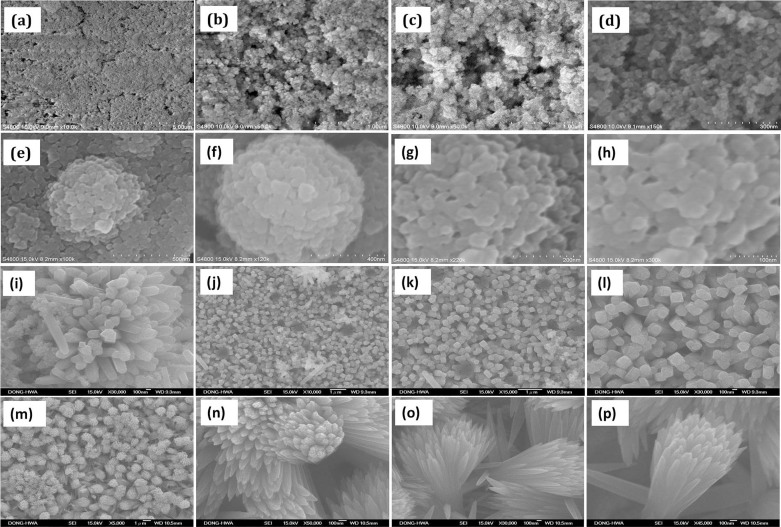
The morphological features of the TiO2 samples are investigated by Field Emission scanning electron microscopy (FESEM). Fig. 1 (a–d) shows the P25 TiO2 nanoparticles that were deposited by doctor blade technique. FESEM images show the compactly arranged and uniformly deposited TiO2 nanoparticles over the substrate. Fig. 1 (e–h) shows FESEM image of the TiO2 nanocoral (TNC) sample that exhibits a novel coral-like morphology with nanopolyps. The diameter of the circular corals is about 400–500 nm, on top of which nanopolyps are nucleated and their average size is about 20 nm. This peculiar morphological feature is beneficial as it provides larger active surface area. Detailed growth mechanism is explained in our previous work34,35,36. FESEM images of the TiO2 nanorods (TNR) are shown in fig. 1 (i–l). Most of TNRs displayed microspheres containing nanorods of nearly 250 nm diameter. Fig. 1 (m–p) shows that the TiO2 nanoflowers (TNF) bunch of aligned nanorods containing petals prepared with RTIL retain the rod like array geometry but the nanorod diameter drastically decreased to nearly 62 nm. It is also to be noted that the nanorods are tapered at the tip and separated to each other.
Figure 1.
FESEM images of hierarchical TiO2 nanostructures: (a–d) Degussa P25 nanoparticles deposited by doctor blade, (sample-1). (e–h) TiO2 nanocorals (TNC) deposited by hydrothermal process from saturated NaCl solvent having (TiCl4) at 120°C, solutions (sample-2), (i–l) TiO2 nanorods (TNR) deposited by hydrothermal process from TTIP in HCl:H2O (1:1v) at 180°C (sample-3) and (m–p) TiO2 nanofloweres (TNF) obtained by hydrothermal process in TTIP:HCl:H2O:[CMIM][HSO4] ionic liquid (sample-4).
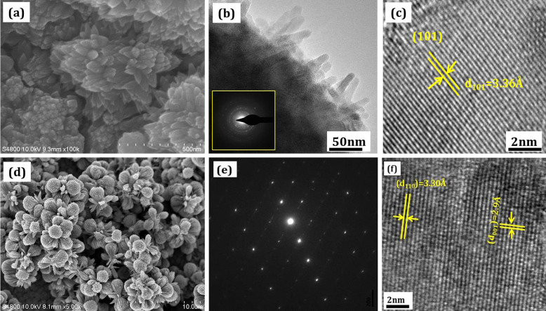
Fig. 2 (a–c) shows the FESEM, selected area electron diffraction (SAED), TEM and HRTEM pattern of TNC sample. The formation of the ring pattern within the dotted line indicates a highly crystalline sample. The morphology of the as-obtained anatase TiO2 nanocorals were characterized by TEM, as shown in Fig. 2 (b). The size of each polyps is around 20–30 nm with high crystallinity. Fig. 2(c) shows an HRTEM image of the respective sample. The lattice planes are clearly indicates that the synthesized nanocorals are highly crystalline in nature. The regular periodic arrangement of the atoms to form atomic plane with an interplanar distance of 3.36Å affirms the growth of anatase TiO2 phase. Fig. 2 (d–f) shows FESEM, SAED and HRTEM micrographs of TNF sample. The spotted SAED indicates the single-crystalline nature of the rutile TiO2 nanoflowers. The formation of the dark spot pattern indicates a single crystalline nature of the sample. It is believed that the synthesized films are composed of single-crystalline rutile TiO2 nanorods that grow in the [001] direction. The clear lattice fringe of the single nanorod of TNF sample is single crystalline along their entire length (fig. 2 (e)). Interplanar spacings, d110 = 3.3Å between the adjacent lattice fringes perpendicular to the rod axis can be assigned to the interplanar distance of rutile TiO2 (110) and d001 = 2.9Å is interplanar distance for the (001) planes along the rod axis that are obtained from the HRTEM lattice fringes of TNF. This indicates the formation of single crystalline rutile phase, in agreement with the XRD results (Supporting information Figure S1 and S2).
Figure 2. High-magnification FESEM images, SAED and HRTEM characterizations of the of the different TiO2 nanostructures in the form of (a–c) TNC, (d–f) TNF.
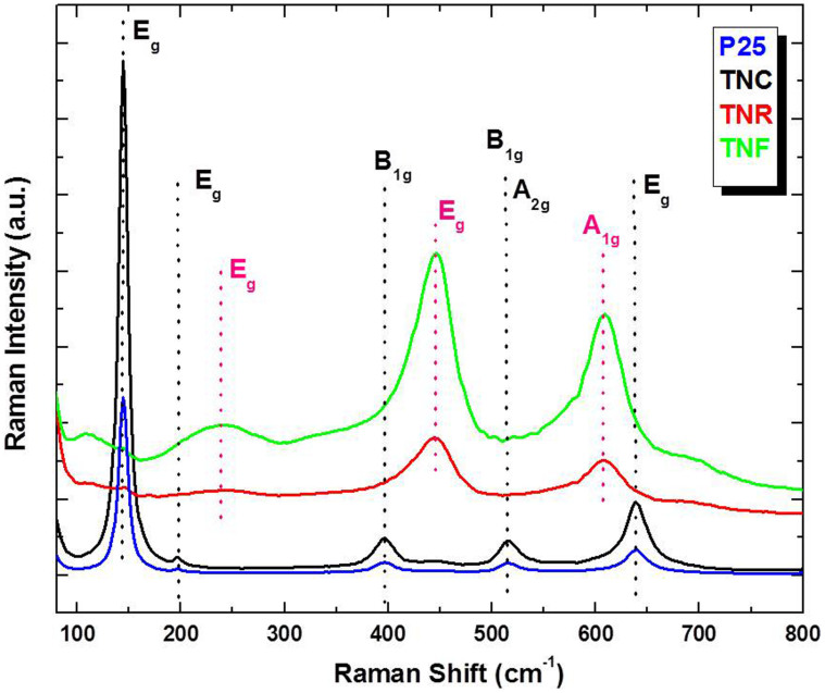
The Fourier transform Raman (FT-Raman) spectra of the films were recorded in the spectral range of 36–2000 cm−1 using FT-Raman spectrometer (Bruker MultiRAM, Germany) that employs a Nd:YAG laser source with an excitation wavelength 1064 nm and resolution 4 cm−1 at 336 mW laser power. The FT-Raman of the P25, TNC, TNR and TNF films are shown in Fig. 3. The ‘tetragonal anatase structured’ TiO2 belongs to D194h (I41/amd) space group (SG) and following normal lattice A1g+B1g+B2g+Eg. The first Eg peak at ~144 cm−1, a characteristic of anatase TiO2 was formed in the P25 as well as TNC samples. The peaks at 516 (corresponding to B1g, A2g) and 635 cm−1 (correspond to Eg) modes of anatase TiO2 are observed. The rutile phase of TiO2 is tetragonal and exhibits symmetry characters of the space group with two TiO2 molecules per unit cell. The TNR and TNF samples show four Raman active fundamental modes that reveals rutile TiO2 at 143 cm−1 (B1g), 447 cm−1 (Eg), 612 cm−1 (A1g), and 826 cm−1 (B2g) expressed as A1g+B1g+B2g+Eg. For the rutile phase two prominent maxima at 445 cm−1 (Eg) and 609 cm−1(A1g), are comparable with that found in the rutile TiO2 single crystal. In addition, there are second-order scattering features, the most prominent one at ~237 cm−1 (Eg) peak due to the multiple-phonon scattering processes, which is also considered as a characteristic Raman peak of rutile type TiO227. In the FT-Raman spectra of our samples, the Eg and A1g modes, as well as the second-order effect at ~237 cm−1, are the major features; the B1g and B2g modes are extremely weak or absent (fig 3). With conversion from TNRs to TNF, the wave number of all peaks decreased relevantly; in particular, the Eg (612 cm−1) mode decreased by about 6 cm−1, while the intensity of second-order Eg mode (~237 cm−1) is drastically increased. The second order Eg at 237 cm−1, a characteristic of rutile TiO2, is more intense and slightly broader and shifted with respect to that of a TNRs sample. This nature is due to phonon confinement effect in which the decrease in the particle dimensions to the nanometer scale can cause a wave number shift and broadening of Raman peaks as a result of phonon confinement. The non-linear behavior of the Eg peak intensity suggests strong light scattering differences among samples, potentially related to changes on the morphological properties of the nanorods and nanoflowers. Figure S4 shows the N2 adsorption–desorption isotherm of the TiO2 samples. The isotherm displays a typical type IV curve while the hysteresis loop is associated with narrow slit-like pores in the sample. The BET specific surface area of the P25, TNC, TNR and TNF sample are 54.7 m2g−1, 73.5 m2g−1, 89.4 m2g−1 and 106.1 m2g−1 respectively. From these data it is clear that the TNF sample has much higher surface area than other TiO2 photoelectrodes. These results clearly reveal that TiO2 nanoflowers facilitates larger amount of dye adsorption as well as effective light harvesting.
Figure 3. FT-Raman spectra of synthesized TNC, TNR and TNF recorded in the wave number range of 35–800 cm−1 with 1064 nm Nd:YAG laser excitation wavelength.
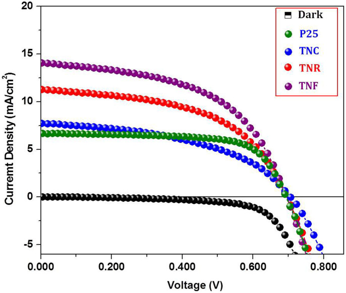
The DSSC devices assembled using the above films were tested under simulated AM1.5G solar illumination (100 mWcm−2). The 0.3 mM ethanolic solution of N-719 (Di-tetrabutylammonium cis-bis(isothiocyanato)bis(2,2′-bipyridyl-4,4′-dicarboxylato)ruthenium(II), Sigma Aldrich) dye solution was used for dye loading. The standard iodide-based electrolyte (TEL-294H, EL-HPE, Dyesol,) was used as the redox electrolyte. Figure 4 shows the J-V plots of different TiO2 morphologies denoted as Dark ( ) P25 (
 ), TNC (
 ), TNR (
 ) and TNF (
 ). The average photovoltaic data were summarized in Table 1. The DSSC based on P25 produced conversion efficiency (η) of 3.18% (Jsc = 6.68 mAcm−2, Voc = 0.692 V, FF = 0.69). The TNC sample shows η of 3.53% (Jsc = 8.63 mAcm−2, Voc = 0.706 V, FF = 0.58). In case of TiO2 nanorods (TNR), it shows Jsc = 11.24 mAcm−2, Voc = 0.699 V, FF = 0.62. The conversion efficiency of TNR comes to be 4.87%. While, the nanoflowers grown from RTIL [CMIM][HSO4] resulted in a big enhancement of Jsc by twice compared to P25. The TNF sample shows η of 6.63% (Jsc = 13.15 mAcm−2, Voc = 0.699 V, FF = 0.67). As a result, power conversion efficiency improved from 3.18% for P25 sample to 6.63% for TNF.
Figure 4. J–V curves of the DSSCs assembled respectively from P25, TNC, TNR and TNF under simulated AM 1.5G solar light (100 mW cm−2).
P25 film obtained from commercial Degussa powder, TNC obtained from the TiCl4 and sat. NaCl; TNR obtained from the TTIP:HCl: H2O; TNF obtained from the TTIP:HCl:H2O:[CMIM][HSO4].
Table 1. Average photovoltaic performance parameters for DSSCs based on the different TiO2 morphologies.
| Sample | Voc (V) | Jsc (mAcm−2)[a] | R at Voc (Ω·cm2) | R at Isc (Ω·cm2) | FF (%) | (η) (%) | Adsorbed Dye (μmol cm−2) | Surface Area m2g−1 |
|---|---|---|---|---|---|---|---|---|
| P25 | 0.692 | 6.68 | 183 | 3152.9 | 69 | 3.18 | 89.1 | 54.7 |
| TNC | 0.706 | 8.63 | 78.1 | 2018.3 | 58 | 3.53 | 97.5 | 73.5 |
| TNR | 0.699 | 11.24 | 74.2 | 2129.5 | 62 | 4.87 | 115.3 | 89.4 |
| TNF | 0.699 | 13.15 | 45.81 | 809.7 | 67 | 6.63 | 129.9 | 106.1 |
[a] Device measured @ 0.5 × 0.5 cm active area illumination.
Using the same dye and redox electrolyte, a DSSC made of a film comprising 20 nm TiO2 anatase nanoparticles produced 3.18% conversion efficiency (Jsc = 6.68 mAcm−2, Voc = 0.692 V, FF = 0.69). From Table 1 it is obvious that the nanoflower rutile film is superior to the P25 nanoparticulate anatase film in the generation of Jsc and η% even though anatase is known to show better efficiency. In order to verify this, the adsorbed amounts of dye were determined by measuring the eluted dye concentration from the porous TiO2 structure. With UV-vis (UV-1800, Shimadzu) absorption spectroscopy P25 sample shows 89.1 μmol·cm−2 which is less as compared to TNC, TNR and TNF samples. The amount of dye loaded by TNF is higher (129.9 μmol·cm−2) compared to both TNC (97.5 μmolcm−2) and TNR (115.3 μmol·cm−2) sample. From the above discussion it is clear that the increment in dye adsorption was simply proportional to the surface area of the TiO2 morphology. Therefore TNF sample provides large surface area for dye adsorption which results in increased efficiency. From Table 1 it is clear that all samples shows FF less than 0.70, which may be due to high series resistance (Rs). In our experiment we used FTO with sheet resistance 15 Ω·cm−2 which will cause the increment in the series resistance.
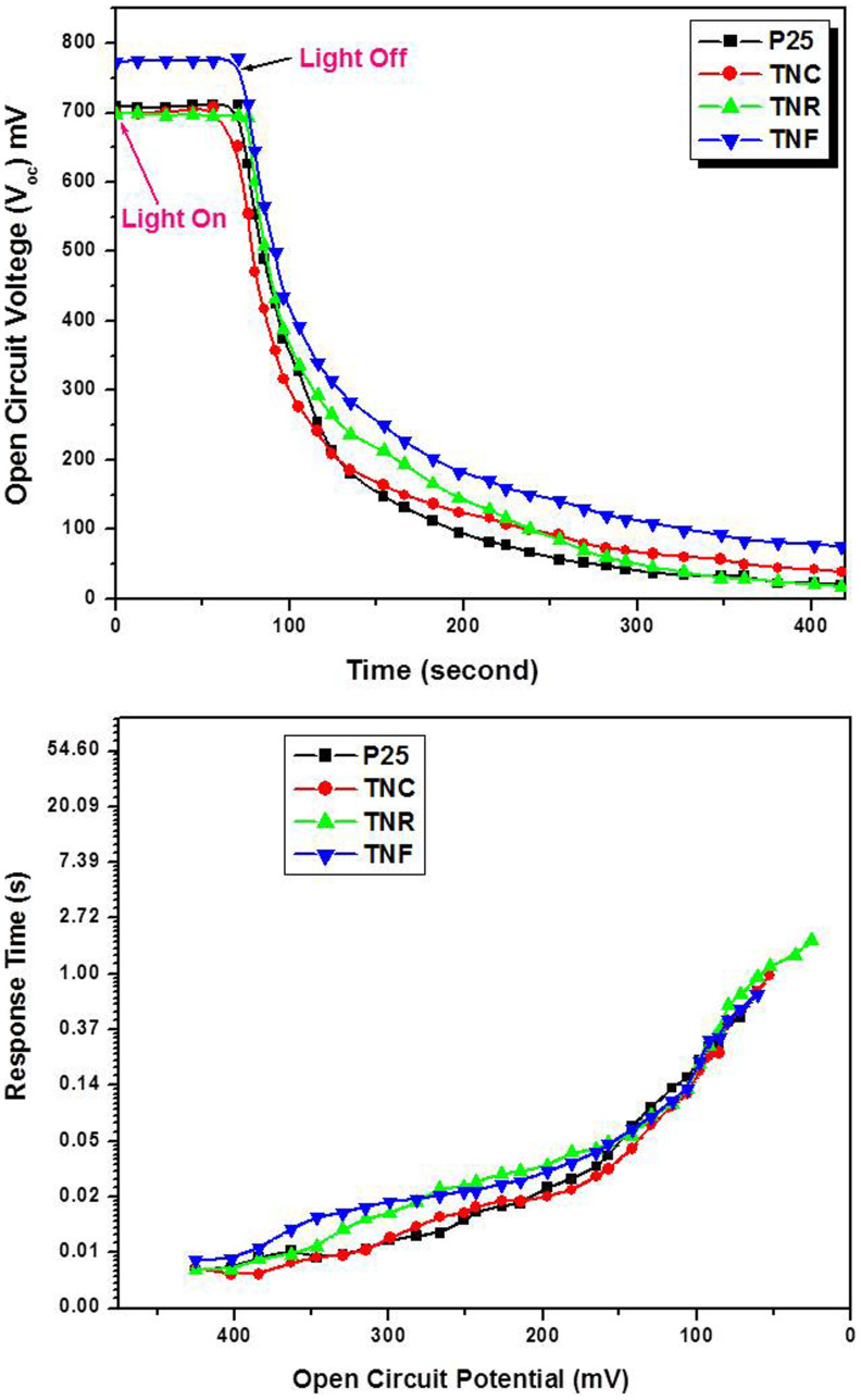
Open-circuit voltage-decay (OCVD) measurements were conducted to investigate the recombination kinetics of these nanostructures. Following the technique as reported by Zaban et al.37 Open-circuit voltage-decay measurements were performed by monitoring the Voc transient during relaxation from an illuminated quasi equilibrium state to the dark equilibrium (Figure 5 (a)). When the visible light illumination on a DSSC at open circuit is interrupted, the excess electrons are removed due to recombination, with the photovoltage decay rate directly related to the electron lifetime.
Figure 5. (a) Photovoltage-decay measurement of TiO2 DSSCs electrodes to illumination excitation (AM 1.5G solar light (100 mWcm−2)), (b) Response time determined by open circuit photovoltage decay for different DSSCs samples.
Appropriate use of OCVD equation, assumes that the recombination is linear with a first-order dependence on electron concentration and that electron recombination occurs only with the electrolyte. Figure 5 shows the OCVD curves measured for various DSSCs, and it appears that the TNF has the slower voltage decay rate as compared to other samples. Figure 5 (b) is the plot of the response time obtained by applying equation to the data in Figure 5 (a). Recombination in all samples is very slow and cells can sustain significant voltages many seconds after light has been turned off. In comparison to P25, TNC, TNR and TNF OCVD measurements, the TNF based DSSCs exhibit the much larger τn values compared to all other samples. The derived electron lifetimes from transient equation, also demonstrate that the TNF electrode has larger τn values compared with those for the other DCCS electrodes. This result indicates that the recombination rate of photogenerated electrons with electrolyte-oxidized species is the slowest in the DSSCs fabricated based on TNF morphology. This effect is also responsible for the higher performance of the DSSCs electrode.
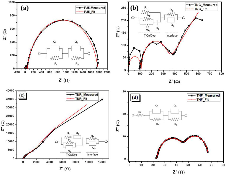
In order to understand the reasons behind such results, we decided to perform electrochemical impedance spectroscopy (EIS) on the assembled cells in the dark at −0.70 V applied potential. Analyzing EIS results using the appropriate transmission line model, gives insights into the interfacial charge transfer processes that take place at the working and counter electrodes/electrolyte interfaces. Typical EIS Nyquist plots of TiO2 DSSCs devices (P25, TNC, TNR and TNF) and their corresponding equivalent circuit fitted plots are shown in Figure 6 (a–d). Inset shows its equivalent circuit used to analyze the impedance spectra. In general, under an applied potential of −0.70 V three phase angle peaks are present. The peak seen in the high frequency region (20 kHz–100 Hz) results from the charge transfer resistance (RCE) and the double layer capacitance (CCE) at the electrolyte/counter electrode interface, whereas the one observed at mid frequencies (1–100 Hz) is due to the charge transfer resistance (RCT) of the electron recombination and the chemical capacitance (C1) at the TiO2/N719/electrolyte interface.
Figure 6. (a–d) Impedance spectra of TiO2 DSSCs electrodes measured in the dark under 20.70 V applied bias.
Inset shows the respective equivalent circuits used to analyze the impedance data.
The third arc at low frequencies (0.1–1 Hz) is characteristic of the Warburg impedance (W1) corresponding to the electrolyte's ions diffusion in a DSSC as seen in the case of TNC sample. The fitted impedance spectra for TNC sample consists of (R3, Q2) which represents the electrode/electrolyte interface and R1 is the shunt resistance in parallel with the TiO2–Dye structure represented by W1, R2, C1. R3 is the charge transfer resistance, RCE and Q2 is the double layer capacitance CCE. While W1 and R2 (or RCT) represent the diffusion resistance and series resistance of the TiO2–Dye structure, C1 represents the TiO2–Dye junction capacitance. In case of nanorods, the W1 gets replaced by the constant phase element Q0, while the remaining circuit elements are the same. For P25 and TNF the equivalent circuits are similar as shown in the inset. The product of the charge-transfer resistance of the electron recombination (RCT or R2 in the case of TNC and TNR while it is R1 in the case of P25 and TNF) and the chemical capacitance (Q1or C1) at the TiO2/N719 interface corresponds to the electron lifetime in the TiO2 film, τe = RCT x Q1.
The series and shunt resistances obtained after fitting the impedance data are shown in Table 2 along with the carrier lifetime estimates. From the Table-2 it is clear that, there is a significant increase in the carrier lifetime for all TiO2 nanostructures prepared by hydrothermal method when compared to P25. The shunt resistance R1 of device P25 and TNR is very high than that of R2 = 2531 and 23 Ω.cm−2 for devices TNC and TNF measured at −0.70 V, respectively. Though the series resistance (R2) of TNF is very less, the shunt resistance also is very small decreasing the efficiency. So better optimization of the TiO2-Dye interface promises further increase in efficiency. Higher RCT for TNC electrode results in lower fill factor, thereby lowering efficiency when compared to TNF based device.
Table 2. Fitted impedance parameters of the DSSC's for different devices.
| Device | Q1 (F) | R2 Ω·cm2[a] | R1 Ω·cm2 | τe ± 17% (ms) |
|---|---|---|---|---|
| P25 | (1.25e-8)1 | 53 | 150000 | 0.00066 |
| TNC | (1.033e-5)1 | 238 | 2246 | 0.245 |
| TNR | (1.495e-5)0.6562 | 2531 | 228900 | 0.112 |
| TNF | (5.753e-5)0.8007 | 23 | 23.8 | 0.116 |
[a] Measured under dark conditions with an applied potential = −0.70 V and a cell area = 0.5 × 0.51 cm2.
For TNF sample increased Jsc may be due to typical morphology of TiO2 sample which will facilitate for effective dye adsorption and the corresponding increase in current. Such morphology will also provide effective light harvesting accessibility. Further, Jsc increased significantly because the size and width of nanflowers are thinner about (~61 nm) compared to TNR (~250 nm) sample, denser and more aligned, which yielded more dye loading and faster electron diffusion. Among the above-mentioned morphologies of nanoflowers (TNF), those grown from the TTIP:HCl:[CMIM][HSO4] solution produced the highest short-circuit photocurrent (13.15 mAcm−2) and power conversion efficiency (6.63%). Therefore, we suggest that TNF are the best candidate for DSSCs application.
Discussion
In conclusion, we have presented first report on a synthetic strategy to deposit different nanostructured TiO2 thin films by simple and cost effective hydrothermal route for dye sensitized solar cells (DSSCs) application. We have also demonstrated a facile way to synthesize novel nanoflower morphology of TiO2 using [CMIM][HSO4] room temperature ionic liquid (RTIL) which is non-toxic and are useful in developing green chemistry approach for efficient DSSCs applications. Furthermore, [CMIM] [HSO4] helped to achieve a high degree of crystallization even at mild annealing temperatures, such as 180°C. Among the above-mentioned morphologies TiO2 nanoflowers (TNF), those grown from the TTIP:HCl:[CMIM][HSO4] solution produced the highest short-circuit photocurrent (13.15 mAcm−2) and power conversion efficiency (6.63%). The TNFs are superior to those grown from the single step hydrothermal system in solar cell performance, typically with current density Jsc (13.15 mAcm−2). Even with a 1.8~μm long nanorod array film, a solar-to-electric power conversion efficiency of 6.63% has been achieved, which is more efficient than a DSSC based on a 1.8 μm thick nanoparticulate film. This method will open a new approach to develop hierarchical functional nanomaterials using ionic liquid and subsequent applications.
Methods
Materials
Titanium tetrachloride (TiCl4) (99.98% Spectrochem, India), and Titanium tetraisopropoxide (TTIP) were purchased from Alfa Aesar. Hydrochloric acid (HCl, 35.46%), sulfuric acid (H2SO4, 99.9%),) nitric acid (HNO3, 38%,) and sodium chloride (NaCl) were obtained from Thomas Baker. Absolute ethanol (99.9%) AR-grade was obtained from Changshu Yangyuan Chemicals China. Conducting FTO glass (fluorine-doped SnO2, resistance 15 Ω cm−2, transmittance 90%, Solaronix) was received from Solaronix, Switzerland. Iodolyte AN-50 (Solaronix) redox electrolyte were used in the DSSCs. The sensitizer used in this work is an organic N719 dye (Di-Tetrabutylammonium cis-bis(isothiocyanato)bis(2,2-bipyridyl-4,4′-dicarboxylato)-ruthenium(II), 95% (NMR)) purchased from Dysol.
Hydrothermal Synthesis of TiO2 Nanocorals (TNC)
TiO2 nanorcorals (TNC) were synthesized by controlled hydrothermal process34,35. In a typical experiment, hydrothermal inorganic precursor solution was prepared by mixing 0.05 M TiCl4 carefully with absolute ethanol in ice-cold bath forming yellow colored titanium chloroalkoxide [TiCl2(OEt)2] solution. A small amount of 0.001 M concentrated hydrochloric acid (HCl, 36%, Thomas Baker) was added as a catalyst and pH of solution was adjusted to 2.1 using nitric acid (HNO3, 38%, Thomas Beaker) as a peptizer. The transparent solution thus prepared was further mixed with saturated solution of 6.8 M NaCl (Extra pure, Thomas Baker). The addition of water causes the hydrolysis of the inorganic moieties, producing in situ ethanol and HCl, the latter being the reason for the high stability of the solution. The final solutions are very acidic and stable for several months at ambient temperature (20–25°C) or 1–2 weeks at 30°C. The solution was stirred for 30 min using magnetic stirrer and transferred into a polytetrafluoroethylene (Teflon)-coated 25 ml vessel. The cleaned glass or TCO substrate was immersed into this solution vertically. It was then sealed and maintained at 120°C for 3 h (at 1.5 kg/cm2 pressure). Upon completion of the reaction, the autoclave was allowed to cool at room temperature and the deposited film was rinsed in double distilled water and finally dried at room temperature. The TiO2 film was whitish, uniform, crack-free and adherent to the substrates, whose adherence was checked by a scotch tape test. The deposited film is designated as TNC.
Hydrothermal Synthesis of TiO2 Nanorods (TNR)
A TiO2 TNR on conducting glass electrodes was prepared by the hydrothermal method. In a typical synthesis, titanium (IV) isopropoxide (0.5 mL) was added to equal volume of distilled water and concentrated HCl. The resulting mixture was stirred for 30 min. The clear transparent solution was then transferred to a Teflon-lined stainless steel autoclave (25 mL), and a piece of F-doped SnO2 (FTO) glass (Solaronix, 15 Ω.cm−2) was immersed in the solution parallel along the wall. The autoclave was sealed and placed in an oven at 180°C for 3 h. After cooling the autoclave to room temperature, the TiO2 films were washed several times with distilled water and dried in oven at 70°C for 1 h designated as TNR.
Hydrothermal Synthesis of TiO2 Nanoflowers (TNF)
TiO2 nanoflowers (TNF) on conducting glass electrodes were prepared by the hydrothermal method as per our previous method36. The TiO2 nanoflowers (TNF) were synthesized by the addition of 0.001 M, 1: 3-ethoxycarbonylethyl-1-methyl-imidazolium chloride [CMIM][HSO4] RTIL in above precursor solution and carried out the same reaction at same 180°C temperature for 3 h and the sample was designated as TNF. For comparison we used P25 Degussa TiO2 nanopaticles and 1.8 μm thick film was fabricated by using well known doctor blade technique. Briefly, 1 g TiO2 nanoparticles paste was prepared using available literature and film was deposited on FTO coated glass substrate and annealed at 450°C for 5 min.
Device fabrication and dye sensitized solar cell tests
The DSSCs properties were measured by Sol2A Oriel New Port Corporation USA, with Keithley-2420 source meter under 1.5 AM illumination. A compact and sealed dye sensitized solar cell (DSSCs) device was fabricated using a standard two-electrode configuration, comprising dye loaded Glass/FTO/P25 (with an active surface area of 0.5 cm2) as photoanode, platinum coated FTO, as a counter electrode which is sealed with the working electrode using a spacer (1 mm) of polyacralamyde. The platinum coated FTO counter electrode, was prepared by dropping a H2PtCl6 solution (0.7 mM) on an FTO glass followed by heating at 400°C for 20 min in air. The dye-adsorbed nanostructured TiO2 electrodes and the Pt counter electrode was sealed with 25 μm-thick Surlyn (SX1170–25, Solaronix) thermoplastic at a pressure of ~210 Kpacm−2 and a temperature of about ~110°C. The Iodolyte AN-50 (Solaronix) electrolyte was inserted through predrilled hole from Pt/FTO counter electrode. Finally device was sealed using thermoplastic. All the measurements were carried out at room temperature in air.
Dye Adsorption Measurement
To measure the adsorbed dye concentration on the TiO2 electrode surface, the dye loaded TiO2 samples were desorbed by a 0.1 M NaOH solution in water and ethanol (50:50, v/v) for 10 min. The dimension of the TiO2 electrode was 1 cm2. The adsorbed dye was quantitatively determined from the absorbance at 510 nm measured by UV-1800, Shimadzu UV-vis spectrophotometer (Resolution 0.01 nm).
For more details of effective dye loading, characterization techniques used for TiO2 samples, device fabrication and dye sensitized solar cell tests, XRD spectra of TiO2 samples refer Fig. S1 and Fig. S2, for FT-IR spectra of TiO2 samples refer Fig. S3, and for Nitrogen adsorption-desorption isotherms plots of TiO2 samples refer to Fig. S4.
Author Contributions
S.S.M., C.K.H. and P.S.P. contributed to the conception and design of the experiments, analysis of the data and writing the paper. S.S.M. carried out all experiments and wrote the paper. S.S.M. and C.A.B. performed EIS measurements, calculations and analyzed data. C.A.B., P.S.P. and P.N.B. participated in the scientific discussion and valuable suggestions during the course of this manuscript. All authors discussed the results and reviewed the manuscript.
Supplementary Material
From nanocorals to nanorods to nanoflowers nanoarchitecture for efficient dye-sensitized solar cells at relatively low film thickness: All Hydrothermal Process
Acknowledgments
One of the authors (SSM) wish to acknowledge DAE-BRNS Mumbai for financial support through the DAE-BRNS project no. 2008/37/8/BRNS/1489 for the 2008–2012. This work was also supported by the Priority Research Centers Program through the National Research Foundation of Korea (NRF) funded by the Ministry of Education, Science and Technology (2009–0094055).
References
- Grätzel M. Photoelectrochemical cells. Nature 414, 338–344 (2001). [DOI] [PubMed] [Google Scholar]
- Yum J. H. et al. Phosphorescent energy relay dye for improved light harvesting response in liquid dye-sensitized solar cells. Energy Environ. Sci. 3, 434–437 (2010). [Google Scholar]
- Wang H. E. et al. Hydrothermal synthesis of ordered single-crystalline rutile TiO2 nanorod arrays on different substrates. Appl. Phys. Lett. 96, 263104–263107 (2010). [Google Scholar]
- Law M., Greene L. E., Johnson J. C., Saykally R. & Yang P. D. Nanowire dye-sensitized solar cells. Nat. Mater. 4, 455–459 (2005). [DOI] [PubMed] [Google Scholar]
- Kang S. H., Kim J. Y., Kim Y., Kim H. S. & Sung Y. E. Surface Modification of Stretched TiO2 Nanotubes for Solid-State Dye-Sensitized Solar Cells. J. Phys. Chem. C 111, 9614–9623 (2007). [Google Scholar]
- Kasuga T., Hiramatsu M., Hoson A. & Niihara T. S. K. Titania Nanotubes Prepared by Chemical Processing. Adv. Mater. 11, 1307–1311 (1995). [Google Scholar]
- Mali S. S., Betty C. A., Bhosale P. N. & Patil P. S. Hydrothermal synthesis of rutile TiO2 with hierarchical microspheres and their characterization. Cryst. Engg. Comm. 13, 6349–6351 (2011). [Google Scholar]
- Gong D. et al. Titanium oxide nanotube arrays prepared by anodic oxidation. J. Mater. Res. 16, 3331–3334 (2001). [Google Scholar]
- Ren X. et al. The selective fabrication of large-area highly ordered TiO2 nanorod and nanotube arrays on conductive transparent substrates via sol–gel electrophoresis. Nanotechnology 20, 365604–365608 (2009). [DOI] [PubMed] [Google Scholar]
- Chu S. Z., Wada K., Inoue S., Hishita S. I. & Kura-shima K. Fabrication and Structural Characteristics of Ordered TiO2−Ru(−RuO2) Nanorods in Porous Anodic Alumina Films on ITO/Glass Substrate. J. Phys. Chem. B 107, 10180–10184 (2003). [Google Scholar]
- Liu B. & Aydil E. S. Growth of Oriented Single-Crystalline Rutile TiO2 Nanorods on Transparent Conducting Substrates for Dye-Sensitized Solar Cells. J. Am. Chem. Soc. 131, 3985–3990 (2009). [DOI] [PubMed] [Google Scholar]
- Wei W., Wang H. & Hu Y. H. A review on PEDOT-based counter electrodes for dye-sensitized solar cells. Int. J. Energy Res. 10.1002/er.3178 (2014). [Google Scholar]
- Wang H., Wei W. & Hu Y. H. NiO as an Efficient Counter Electrode Catalyst for Dye-Sensitized Solar Cells. Top Catal. 57, 607–611 (2014). [Google Scholar]
- Wang H., Sun K., Tao F., Stacchiola D. J. & Hu Y. H. 3D Honeycomb-Like Structured Graphene and Its High Efficiency as a Counter-Electrode Catalyst for Dye-Sensitized Solar Cells. Angew. Chem. Int. Ed. 52, 9210–9214 (2013). [DOI] [PubMed] [Google Scholar]
- Wang H. & Hu Y. H. Graphene as a counter electrode material for dye-sensitized solar cells. Energy Environ. Sci. 5, 8182–8188 (2012). [Google Scholar]
- Wang H., Leonard S. L. & Hu Y. H. Promoting Effect of Graphene on Dye-Sensitized Solar Cells. Ind. Eng. Chem. Res. 51, 10613–10620 (2012). [Google Scholar]
- Wei W., Wang H. & Hu Y. H. Unusual particle-size-induced promoter-to-poison transition of ZrN in counter electrodes for dye-sensitized solar cells. J. Mater. Chem. A 1, 14350–14357 (2013). [Google Scholar]
- Wang H., Wei W. & Hu Y. H. Efficient ZnO-based counter electrodes for dye-sensitized solar cells. J. Mater. Chem. A 1, 6622–6628 (2013). [Google Scholar]
- Duan X., Lian J., Ma J., Kim T. & Zheng W. Shape-Controlled Synthesis of Metal Carbonate Nanostructure via Ionic Liquid-Assisted Hydrothermal Route:The Case of Manganese Carbonate. Cry. Growth Design 10, 4449–4455 (2010). [Google Scholar]
- Parnham E. R. & Morris R. E. Ionothermal synthesis using a hydrophobic ionic liquid as solvent in the preparation of a novel aluminophosphate chain structure. J. Mater. Chem. 16, 3682–3684 (2006). [Google Scholar]
- Taubert A. CuCl Nanoplatelets from an Ionic Liquid-Crystal Precursor. Angew. Chem., Int. Ed. 43, 5380–5382 (2009). [DOI] [PubMed] [Google Scholar]
- Parnham E. R. & Morris R. E. Ionothermal Synthesis of Zeolites, Metal–Organic Frameworks, and Inorganic–Organic Hybrids. Acc. Chem. Res. 40, 1005–1013(2007). [DOI] [PubMed] [Google Scholar]
- Yoo K., Choi H. & Dionysiou D. D. Ionic liquid assisted preparation of nanostructured TiO2 particles. Chem. Commun. 2000–2001 (2004). [DOI] [PubMed] [Google Scholar]
- Cooper E. R. et al. Ionic liquids and eutectic mixtures as solvent and template in synthesis of zeolite analogues. Nature 430, 1012–1016 (2004). [DOI] [PubMed] [Google Scholar]
- Zhou Y. & Antonietti M. Synthesis of Very Small TiO2 Nanocrystals in a Room-Temperature Ionic Liquid and Their Self-Assembly toward Mesoporous Spherical Aggregates. J. Am. Chem. Soc. 125, 14960–14961 (2003). [DOI] [PubMed] [Google Scholar]
- Ding K. L. et al. Facile Synthesis of High Quality TiO2 Nanocrystals in Ionic Liquid via a Microwave-Assisted Process. J. Am. Chem. Soc. 129, 6362–6363 (2007). [DOI] [PubMed] [Google Scholar]
- Yoo K. S., Choi H. & Dionysiou D. D. Synthesis of anatase nanostructured TiO2 particles at low temperature using ionic liquid for photocatalysis. Catal. Commun. 6, 259–262 (2005). [Google Scholar]
- Liu Y. et al. Preparation and Properties of Nanostructure Anatase TiO2 Monoliths Using 1-Butyl-3-methylimidazolium Tetrafluoroborate Room-Temperature Ionic Liquids as Template Solvents. Cryst. Growth Des. 5, 1643–1649 (2005). [Google Scholar]
- Nakashima T. & Kimizuka N. Interfacial Synthesis of Hollow TiO2 Microspheres in Ionic Liquids. J. Am. Chem. Soc. 125, 6386–6387 (2003). [DOI] [PubMed] [Google Scholar]
- Welton T. Room-Temperature Ionic Liquids. Solvents for Synthesis and Catalysis. Chem. Rev. 99, 2071–2084 (1999). [DOI] [PubMed] [Google Scholar]
- Yu N., Gong L., Song H., Liu Y. & Yin D. Ionic liquid of [Bmim]+ Cl− for the preparation of hierarchical nanostructured rutile titania. J. Solid State Chem. 180, 799–803 (2007). [Google Scholar]
- Kaper H. et al. Direct Low-Temperature Synthesis of Rutile Nanostructures in Ionic Liquids. Small 3, 1753–1763 (2007). [DOI] [PubMed] [Google Scholar]
- Jia X. et al. Microwave-assisted synthesis of anatase TiO2 nanorods with mesopores. Nanotechnology 18, 075602–075607 (2007). [DOI] [PubMed] [Google Scholar]
- Mali S. S. et al. Nanocoral architecture of TiO2 by hydrothermal process: Synthesis and Characterization. Appl. Surf. Sci. 257, 9737–9746 (2011). [Google Scholar]
- Mali S. S. et al. CdS-sensitized TiO2 nanocorals: hydrothermal synthesis, characterization, Application. Photochem. Photobiol. Sci. 10, 1652–1658 (2011). [DOI] [PubMed] [Google Scholar]
- Mali S. S. et al. Hydrothermal synthesis of rutile TiO2 nanoflowers using Brønsted Acidic Ionic Liquid [BAIL]: Synthesis, characterization and growth mechanism. CrystEngComm 14, 1920–1924 (2012). [Google Scholar]
- Zaban A. Greenshtein M. & Bisquert J. Determination of the Electron Lifetime in Nanocrystalline Dye Solar Cells by Open-Circuit Voltage Decay Measurements. ChemPhysChem 4, 859–864 (2003). [DOI] [PubMed] [Google Scholar]
Associated Data
This section collects any data citations, data availability statements, or supplementary materials included in this article.
Supplementary Materials
From nanocorals to nanorods to nanoflowers nanoarchitecture for efficient dye-sensitized solar cells at relatively low film thickness: All Hydrothermal Process


