Abstract
Targeted transcranial stimulation with electric currents requires accurate models of the current flow from scalp electrodes to the human brain. Idiosyncratic anatomy of individual brains and heads leads to significant variability in such current flows across subjects, thus, necessitating accurate individualized head models. Here we report on an automated processing chain that computes current distributions in the head starting from a structural magnetic resonance image (MRI). The main purpose of automating this process is to reduce the substantial effort currently required for manual segmentation, electrode placement, and solving of finite element models. In doing so, several weeks of manual labor were reduced to no more than 4 hours of computation time and minimal user interaction, while current-flow results for the automated method deviated by less than 27.9% from the manual method. Key facilitating factors are the addition of three tissue types (skull, scalp and air) to a state-of-the-art automated segmentation process, morphological processing to correct small but important segmentation errors, and automated placement of small electrodes based on easily reproducible standard electrode configurations. We anticipate that such an automated processing will become an indispensable tool to individualize transcranial direct current stimulation (tDCS) therapy.
I. INTRODUCTION
Transcranial direct current stimulation (tDCS) applies weak constant currents (ranging from 0.2 mA to 2 mA) to the surface of the scalp [1]–[3]. Researches have shown that it can improve performance in some learning tasks and it has shown promise as a potential therapy for a number of neurological disorders such as depression, fibromyalgia and stroke [4]–[7]. In conventional tDCS protocols, saline-soaked large-pad sponges (25–35 cm2) are used [1]. However, these are cumbersome and result in non-focal current distributions on the brain. In contrast, high-definition tDCS (HD-tDCS) uses a number of gel-based ring electrodes, and modeling studies have shown that this can be used to improve targeting [8]. HD-tDCS provides flexibility in placing multiple electrodes on the scalp. Both focality as well as intensity can be optimized by an appropriate choice of current intensity through each of the electrodes [9].
To estimate and target current flows one requires accurate anatomical models of the human head. Unfortunately, brain anatomy varies significantly among subjects due to the idiosyncratic folding of cortex, skull thickness and the volume of cerebrospinal fluid (CSF). These anatomical variabilities can greatly affect the current flow in the head. Therefore, to assure accurate and effective targeting it is paramount to use anatomically accurate head models of the individual subjects, which should capture the main structures affecting electrical conductivity: brain, ventricles, CSF, skull, scalp, and air cavities. All of these can be deduced from intensity contrasts in anatomical magnetic resonance images (MRI), which are readily available in many clinical settings. However, the need for individualized models is currently encumbered by the labor intensive process of manually segmenting an MRI image, placing electrodes on the resulting head model, and computing current-flow distributions using the finite element method [8]. In total this process at present can take up to several weeks with the majority of time consumed by manual segmentation. While a number of automated segmentation techniques are freely available for the human brain, at present none gives satisfactory results on the entire volume of the head.
This paper presents the results of a development effort to fully automate current-flow modeling for individualized treatment with the HD-tDCS. Based on the T1-weighted MRI image of a given subject, a tissue segmentation is established, virtual electrodes are placed on standard scalp locations and a finite element model (FEM) of current flow is solved for each electrode/reference pair. With this, one can then readily compute the optimal electrode configuration for a desired target [9] on an individual subject basis. We compared this automated method with the traditional manual method in terms of segmentation accuracy and accuracy of resulting current flows. Results show that the automated process can achieve a substantial benefit in time and labor with only a modest loss in accuracy.
II. METHODS AND RESULTS
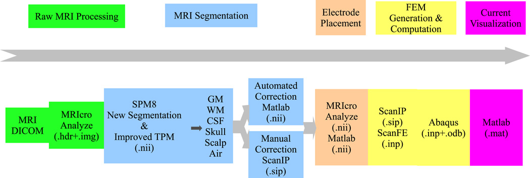
The entire processing chain is shown in Fig. 1.
Fig. 1.
Processing chain for individualized current-flow modeling.
A. MRI Segmentation Performances
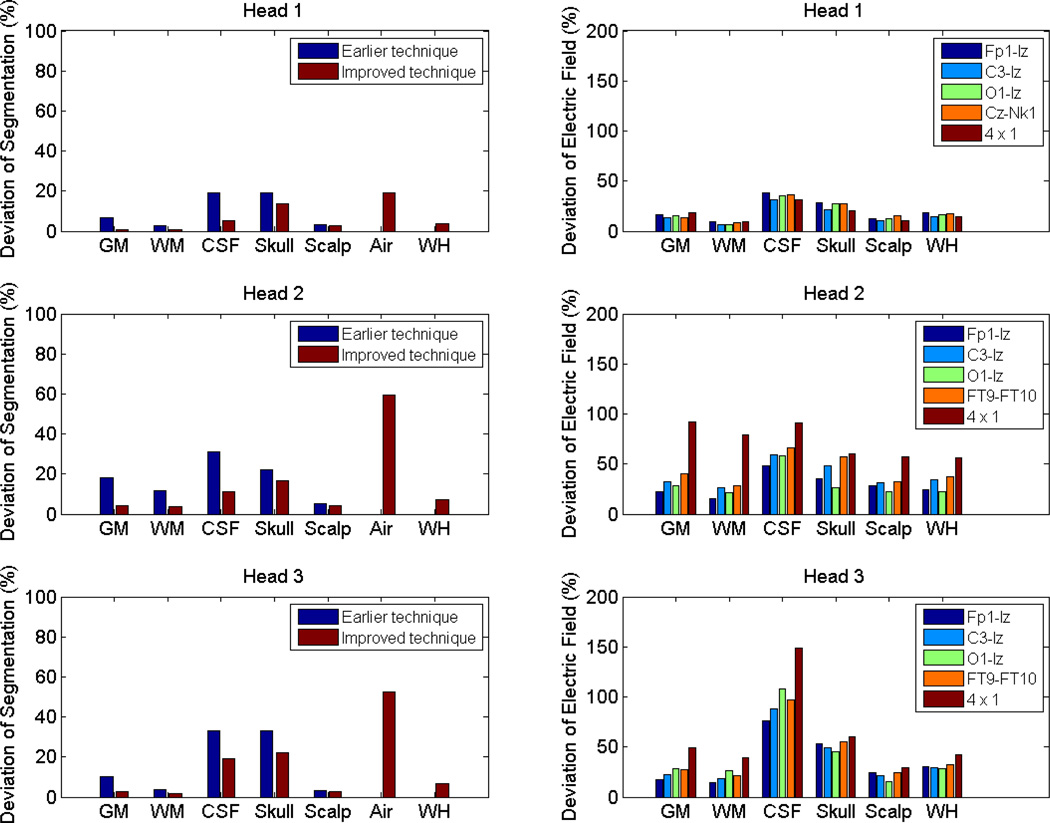
T1-weighted MRI scans of the head were performed on three healthy subjects (two males, average age 35.7 years, range 33–40 years) with an isotropic resolution of 1 mm3. These MRI images were segmented by a probabilistic segmentation routine (New Segmentation, an extension of Unified Segmentation [10]), which is a function of Statistical Parametric Mapping 8 (SPM8, Wellcome Trust Centre for Neuroimaging, London, UK). An improved Tissue Probability Map (TPM, see [11] for details) was used, and each head was segmented into six tissue types: gray matter (GM), white matter (WM), CSF, skull, scalp and air. For subsequent FEM analysis in current-flow modeling, these resulting six tissues were converted into binary masks, and errors in these masks such as rough tissue surface, discontinuities in CSF and skull layers, and disconnected regions were corrected by an automated routine in Matlab (R2010b, Math-Works, Natick, MA) using Gaussian filters, morphological and Boolean operations. To evaluate the performance of this automated algorithm, we also performed manual corrections in ScanIP (version 4.2, Simpleware Ltd, Exeter, UK). Then the deviation of automated segmentation results from manual segmentation was calculated, as shown in Fig. 2 (left column).
Fig. 2.
The deviations of automated segmentation results (left column) and electric fields obtained from automated method (right column), as compared to manual method. For each head, the last group (WH) stands for whole head. Note that in the left column, air was not evaluated in the earlier technique (thus no result for WH). In the right column, it is the deviation of improved automated technique from manual method, and air was not evaluated since we do not care about the current flow in the air.
The average segmentation deviation of the whole head across subjects is 5.8%. While the averaged deviations of CSF, skull and air are somewhat higher (CSF 11.8%, skull 17.5%, air 43.8%), the overall deviations are dominated by the large volume of GM, WM and scalp, which have relatively lower averaged deviations (GM 2.8%, WM 1.9%, scalp 3.2%).
Fig. 2 (left column) also compares the segmentation accuracy with an earlier version of our technique [11]. The TPMs are largely the same, while the post-processing technique has been improved by ensuring continuities of CSF and skull, and by adding mask smoothing (including smoothing air mask). These improvements are important for the purpose of current-flow modeling. For the average segmentation deviations of the first five tissue types, the earlier method leads to a deviation of 10.2%, 17.7%, 16.6% (for Head 1, 2, 3, respectively), and the improved version results in 4.6%, 8.0%, 9.6%, respectively. Pairwise t-test shows that the improved post-processing technique outperforms the earlier version (t(2) = 6.2, p = 0.02).
B. Current-Flow Modeling Results
Electrodes were placed following the convention of the standard 10-10 international system [12] for both automatically and manually corrected tissue masks. An additional row of electrodes and four additional electrodes around the neck were placed on Head 1 to allow potential deeper lower lying cortical targets and distant reference electrodes. To avoid complications in automatically placing electrodes near or behind the ear-lobes we omitted positions TP9 and TP10 in all the three heads (Fig. 3a). Electrode placement was implemented in Matlab, intialized by four points (nasion, inion, pre-auricular right and pre-auricular left) provided by the user.
Fig. 3.
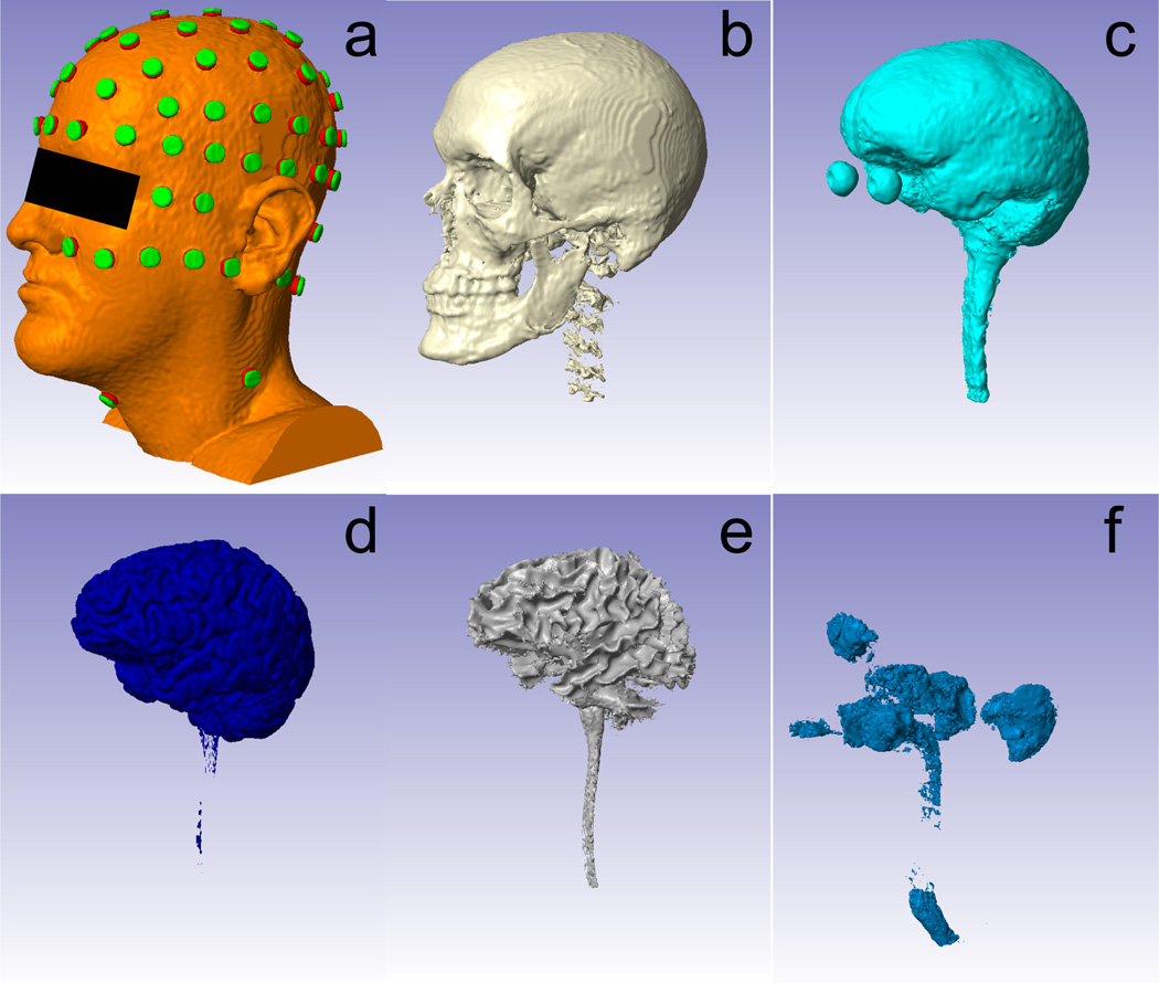
Head model established from six tissue types and electrodes. From a to f: scalp (with electrodes placed), skull, CSF, GM, WM, air. Note that the air outside the head was removed in the air mask since it is not needed in the current-flow modeling.
After electrode placement, a volume conductor model can be established for the whole head, with each tissue mask representing an area of uniform conductivity (Fig. 3). ScanIP (+ScanFE Module) was used to generate the finite element model for the whole volume with adaptive irregular element sizes (ScanFE-Free algorithm). Separate models were constructed from the automatically corrected masks and the manual masks. When current applied to the FEM model of the head, the resulting electric potential distribution V in the volume satisfies Laplace’s Equation [13]:
| (1) |
where J⃗, E⃗ are the current density and electric field, respectively, σ is the conductivity for a specific tissue type, and ∇⃗ is the gradient operator.
Abaqus (version 6.9, SIMULIA, Providence, RI) was used to solve the Laplace equation, with the following boundary conditions: electric insulation for all outer boundaries: n⃗ · J⃗ = 0; continuity for inner boundaries: n⃗ · (J⃗1 − J⃗2) = 0; inward current flow for anode: −n⃗ · J⃗ = Jn; and ground for cathode(s): V = 0. n⃗ is the normal vector of the boundaries, J⃗1 and J⃗2 are current densities in two different tissues, Jn is the amount of stimulating current, which was set to 1 A/m2, and each tissue type was assigned a conductivity as in [9].We implemented both bipolar and 4 × 1 configurations [8] when simulating the current flows. In the bipolar configuration, we chose Iz as cathode, and selected the anode from three different regions on the scalp: forehead (Fp1), motor area (C3) and occipital area (O1). We also simulated a distant reference in Head 1: Cz as anode and front neck electrode (Nk1) as cathode. In Head 2 and Head 3, since no neck electrodes were placed, electrode pair FT9-FT10 was solved. In the 4 × 1 configuration, C4 was set as anode and the four surrounding electrodes (FC2, FC6, CP2, CP6) were cathodes.
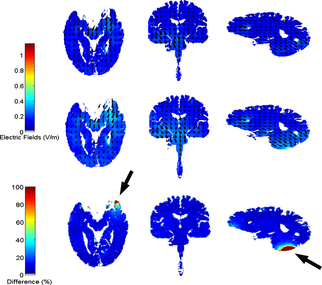
The solutions from Abaqus are the distributions of electric field induced by the stimulating current. They were imported into Matlab and interpolated onto a regular grid with the same dimension and resolution (i.e. 1 mm3) as the original MRI data. Electric fields from both manual and automated methods (the present improved technique) were solved, visualized and compared. As an example, Fig. 4 shows the distributions of electric fields from both methods in GM and WM for Head 1. Note that the electric field shown here is recalibrated corresponding to a 1 mA current injection. The distributions from manual and automated methods are similar to each other except close to the electrode locations due to the local structural differences. Fig. 2 (right column) shows the deviations of the automated results from the manual results.
Fig. 4.
The distributions of electric fields in GM and WM in Head 1 for the manual (first row) and automated method (second row), and the difference of the two methods (third row). Arrows indicate the approximate electrode locations.
The average deviation of electric field across the entire head for all subjects and configurations is 27.9%. This value is approximately five times of the overall segmentation deviation, indicating that the current flow is sensitive to the structural differences. In particular, the segmentation differences in CSF and skull in heads 2 and 3 seem to lead to large deviations in the computed electric field. This is expected as the stark contrast of conductivity values between these two areas causes strong blurring of current distributions. It is especially pronounced in the 4 × 1 configuration which is dominated by the local skull/CSF distribution. It should also be noted that Head 1 has a much better image quality (in terms of intensity contrast) than Head 2 and 3, leading to a much better performance in Head 1. (In fact, Head 1 was scanned on a different scanner with different scanning parameters from Head 2 and 3.)
C. Computation Time Comparison
The moderate loss in accuracy comes at a tremendous advantage in computational time and workload. Typically, manual correction of segmentation errors and manual electrode placement is a labor intensive process which requires several weeks of full-time work. In contrast, with this automated processing method, segmentation touch up and electrode placement take at most 10 minutes. The whole process to compute a current-flow model requires up to 4 hours, with the majority taken up by FEM generation (1–2 hours, ScanIP) and FEM solving (1–1.5 hours, Abaqus) for a typical mesh size of 1.5 million nodes. Therefore, one can quickly simulate the current distribution in the head between any desired pair of electrodes for a given subject. This is very useful for clinical applications since doctors can obtain tDCS forward models several hours after the MRI scan of the patient and plan the strategy for electric stimulation therapy based on these simulation results. To this end, future work will focus on packaging this automated process into a software with a user-friendly interface.
III. CONCLUSIONS
This paper proposed a fully automated processing chain for the simulation of current flows in the head for tDCS therapy. It automated the traditional manual methods in correction of segmentation errors, electrode placement and finite element model solving, reducing the total processing time from weeks to hours. Meanwhile, the average deviations of segmentation results and current-flow results are limited to just 5.8% and 27.9%, respectively. This opens up the possibility of subject-specific tDCS therapy, which was not feasible in practice up to now.
Footnotes
This work was supported by DARPA/DSO Accelerated Learning Program, Grant No. D10AP0051 and NIH-NINDS STTR, Grant No. 1R41NS076123.
Contributor Information
Yu Huang, Email: yhuang16@ccny.cuny.edu.
Christopher Rorden, Email: rorden@sc.edu.
REFERENCES
- 1.Nitsche MA, Paulus W. Excitability Changes Induced in the Human Motor Cortex by Weak Transcranial Direct Current Stimulation. Journal of Physiology. 2000 Sep;527(no. 3):633–639. doi: 10.1111/j.1469-7793.2000.t01-1-00633.x. [DOI] [PMC free article] [PubMed] [Google Scholar]
- 2.Marshall L, Mlle M, Siebner HR, Born J. Bifrontal trans-cranial direct current stimulation slows reaction time in a working memory task. BMC Neuroscience. 2005 Apr;6(no. 1):23. doi: 10.1186/1471-2202-6-23. [DOI] [PMC free article] [PubMed] [Google Scholar]
- 3.Iyer MB, Mattu U, Grafman J, Lomarev M, Sato S, Wassermann EM. Safety and Cognitive Effect of Frontal DC Brain Polarization in Healthy Individuals. Neurology. 2005 Mar;64(no. 5):872–875. doi: 10.1212/01.WNL.0000152986.07469.E9. [DOI] [PubMed] [Google Scholar]
- 4.Nitsche MA, Schauenburg A, Lang N, Liebetanz D, Exner C, Paulus W, Tergau F. Facilitation of Implicit Motor Learning by Weak Transcranial Direct Current Stimulation of the Primary Motor Cortex in the Human. Journal of Cognitive Neuroscience. 2003;15(no. 4):619–626. doi: 10.1162/089892903321662994. [DOI] [PubMed] [Google Scholar]
- 5.Bikson M, Bulow P, Stiller J, Datta A, Battaglia F, Karnup S, Postolache T. Transcranial direct current stimulation for major depression: A general system for quantifying transcranial electrotherapy dosage. Current Treatment Options in Neurology. 2008;10(no. 5):377–385. doi: 10.1007/s11940-008-0040-y. [DOI] [PubMed] [Google Scholar]
- 6.Fregni F, Gimenes R, Valle AC, Ferreira MJL, Rocha RR, Natalle L, Bravo R, Rigonatti SP, Freedman SD, Nitsche MA, PascualLeone A, Boggio PS. A randomized, sham-controlled, proof of principle study of transcranial direct current stimulation for the treatment of pain in fibromyalgia. Arthritis & Rheumatism. 2006 Dec;54(no. 12):3988–3998. doi: 10.1002/art.22195. [DOI] [PubMed] [Google Scholar]
- 7.Schlaug G, Renga V, Nair D. Transcranial Direct Current Stimulation in Stroke Recovery. Archives of Neurology. 2008 Dec;65(no. 12):1571–1576. doi: 10.1001/archneur.65.12.1571. [DOI] [PMC free article] [PubMed] [Google Scholar]
- 8.Datta A, Bansal V, Diaz J, Patel J, Reato D, Bikson M. Gyriprecise head model of transcranial DC stimulation: Improved spatial focality using a ring electrode versus conventional rectangular pad. Brain Stimulation. 2009 Oct;2(no. 4):201–207. doi: 10.1016/j.brs.2009.03.005. [DOI] [PMC free article] [PubMed] [Google Scholar]
- 9.Dmochowski JP, Datta A, Bikson M, Su Y, Parra LC. Optimized multi-electrode stimulation increases focality and intensity at target. Journal of Neural Engineering. 2011 Aug;8(no. 4):046011. doi: 10.1088/1741-2560/8/4/046011. [DOI] [PubMed] [Google Scholar]
- 10.Ashburner J, Friston KJ. Unified segmentation. NeuroImage. 2005 Jul;26(no. 3):839–851. doi: 10.1016/j.neuroimage.2005.02.018. [DOI] [PubMed] [Google Scholar]
- 11.Rorden C, Parra LC, Bikson M. Segmentation for Electrophysiological Source Localization and Electrical Stimulation. Journal of Cognitive Neuroscience. (submitted). [Google Scholar]
- 12. http://www.easycap.de/easycap/ (Date: 03-15-2012).
- 13.Griffiths DJ, Ruppeiner G. Introduction to Electrodynamics. Upper Saddle River, NJ: Prentice-Hall; 1999. [Google Scholar]


