Abstract
Aim:
To investigate the structural basis underlying potency and selectivity of a series of novel analogues of thieno[2,3-d]pyrimidin-4-yl hydrazones as cyclin-dependent kinase 4 (CDK4) inhibitors and to use this information for drug design strategies.
Methods:
Three-dimensional quantitative structure-activity relationship (3D-QSAR) and three-dimensional quantitative structure-selectivity relationship (3D-QSSR) models using comparative molecular field analysis (CoMFA) were conducted on a training set of 48 compounds. Partial least squares (PLS) analysis was employed. External validation was performed with a test set of 9 compounds.
Results:
The obtained 3D-QSAR model (q2=0.724, r2=0.965, r2pred=0.945) and 3D-QSSR model (q2=0.742, r2=0.923, r2pred=0.863) were robust and predictive. Contour maps with good compatibility to active binding sites provided insight into the potentially important structural features required to enhance activity and selectivity. The contour maps indicated that bulky groups at R1 position could potentially enhance CDK4 inhibitory activity, whereas bulky groups at R3 position have the opposite effect. Appropriate incorporation of bulky electropositive groups at R4 position is favorable and could improve both potency and selectivity to CDK4.
Conclusion:
These two models provide useful information to guide drug design strategies aimed at obtaining potent and selective CDK4 inhibitors.
Keywords: 3D-QSAR, 3D-QSSR, CoMFA, cyclin-dependent kinase 4, cyclin-dependent kinase 2
Introduction
Cyclin-dependent kinases are serine/threonine protein kinases with key roles in regulating cell cycle progression, transcription and neuronal function of the eukaryotic cells1,2,3. Thus far, 21 CDKs isoforms have been identified2. The active holoenzyme of CDK4 and its positive regulators (D type cyclins) are critical for regulating the transition through the G1/S phase of the cell cycle1. Overexpression of CDK4 has been identified in a wide variety of cancers4,5,6. In contrast, overexpression occurs less frequently for other CDKs. Thus, CDK4 is a potentially druggable anti-cancer target, more so than other CDKs. Malumbres et al7 have reported that tumorigenesis may be suppressed by knockdown of CDK4 in mammary tumor cells. Moreover, most human cancers arising from tumor suppressor mutations are frequently linked to the loss of function of p16INK4, an endogenous CDK4 and CDK6 negative regulator8,9. Thus, we hypothesize that selective inhibition of CDK4 activity may result in effective cancer suppression. For these reasons, developing potent and selective CDK4 inhibitors would be a valuable approach in cancer chemotherapy as the resulting compounds would have fewer off-target effects and are anticipated to be generally less cytotoxic.
However, due to the high sequence identity and the common folding patterns of the ATP binding pocket, it is not easy to improve the selectivity of CDK inhibitors. In the case of CDK2 and CDK4, their active binding sites are predicted to be very similar because the amino acid sequence identity between these two kinases is 72%10. How can we obtain the CDK4-specific inhibitors based on such minor differences in the active binding site? Mclnnes et al11 hypothesized that inhibitors containing positively charged groups at physiological pH would be electrostatically attracted to the negatively charged Asp99 and Glu144 of CDK4. These same groups would concurrently be electrostatically repelled by the positively charged Lys89 of CDK2, hence giving rise to enhanced CDK4 selectivity. Indeed, the selectivity of the CDK4 inhibitor PD018381212,13 may be attributed to the presence of a positively charged nitrogen atom in the molecule.
In this report, Comparative Molecular Field Analysis (CoMFA) analysis14 was used to establish the quantitative structure activity and structure selectivity relationships of a series of novel positively charged thieno[2,3-d]pyrimidin-4-yl hydrazine analogs that were previously reported to be potent CDK4 inhibitors with marked selectivity for CDK4 versus CDK2. Herein, the contribution of the positively charged groups in rendering CDK4 selectivity was investigated in detail. In addition, steric and electrostatic effects on CDK4 binding affinity and specificity of these compounds were analyzed to guide future drug design efforts.
Materials and methods
Data sets
The thieno[2,3-d]pyrimidin-4-yl hydrazines investigated in this report were synthesized by Horiuchi and co-workers15,16,17. Of the original 68 reported compounds, 11 were discarded due to their low and indeterminate potencies (IC50 (CDK4)>20 μg/mL) and/or indeterminate selectivity. The remaining 57 compounds were randomly divided into a training set (48 compounds) and a test set (9 compounds) for the derivation of CoMFA models. The IC50 values of the remaining compounds (in μmol/L) were converted to pIC50 as a measure of CDK4 potency, and the index for the CDK4 selectivity was represented by log[IC50 (CDK2)/IC50(CDK4)] in the CoMFA analysis. Structures and experimental values of these inhibitors are listed in Table 1.
Table 1. Structures and actual pIC50 (CDK4) and log[IC50 (CDK2)/IC50 (CDK4)] values of thieno[2,3-d]pyrim-idin-4-yl hydrazone analogues.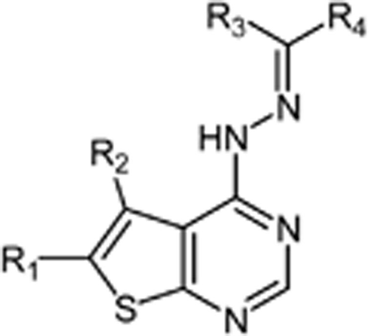
| Compound | R1 | R2 | R3 | R4 | Actual |
|
|---|---|---|---|---|---|---|
| pIC50 (CDK4) | log[IC50 (CDK2)/IC50 (CDK4)] | |||||
| 1 | Et | H | H | 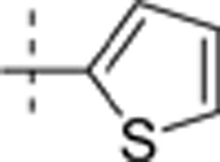 |
5.584 | 0.166 |
| 2 | Me | H | H | 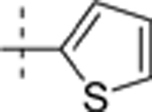 |
5.159 | −0.048 |
| 3 | i-Pr | H | H | 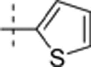 |
6.781 | 0.845 |
| 4 | t-Bu | H | H | 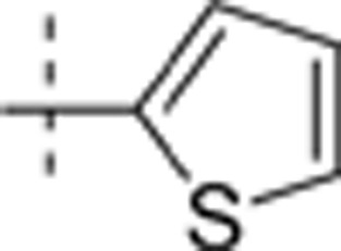 |
6.421 | 0.669 |
| 5 | Me | Et | H | 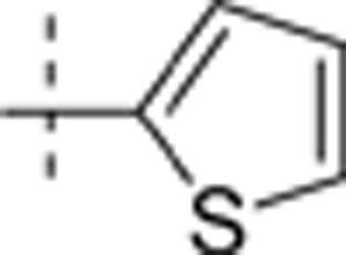 |
4.276 | −0.125 |
| 6 | i-Pr | H | Me | 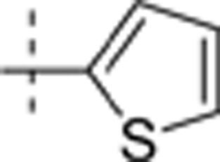 |
5.053 | 0.502 |
| 7 | Et | H | H | t-Bu | 4.775 | −0.064 |
| 8 | Et | H | H | 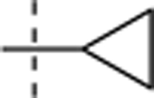 |
4.886 | 0.108 |
| 9 | i-Pr | H | H | 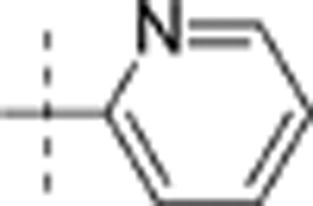 |
5.528 | 0.547 |
| 10 | i-Pr | H | H | 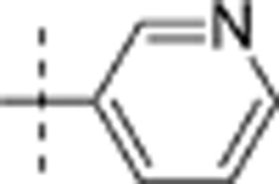 |
5.732 | 0.105 |
| 11 | i-Pr | H | H | 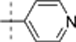 |
6.093 | 0.138 |
| 12 | i-Pr | H | H | Phenyl | 5.799 | 0.272 |
| 13 | i-Pr | H | H | 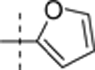 |
5.871 | 0.149 |
| 14 | t-Bu | H | H | 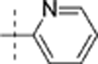 |
5.539 | 0.493 |
| 15 | t-Bu | H | H | 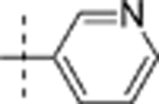 |
5.794 | 0.0492 |
| 16 | t-Bu | H | H | 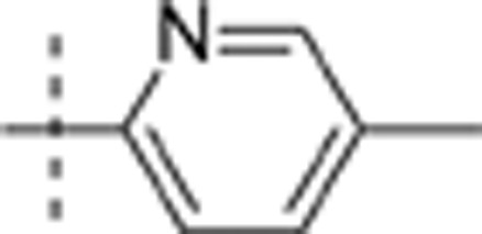 |
5.567 | 1.135 |
| 17 | t-Bu | H | H | 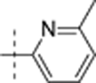 |
5.796 | 1.123 |
| 18 | t-Bu | H | H | 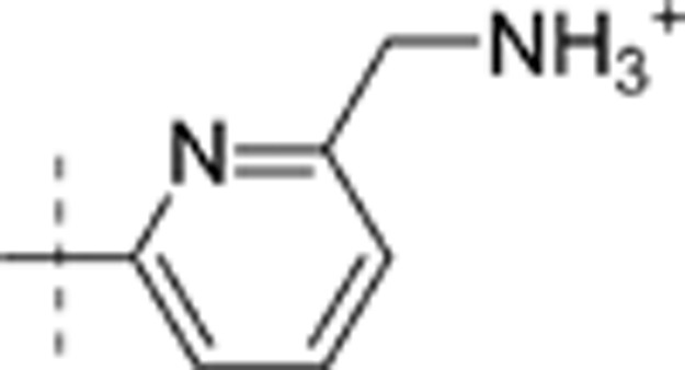 |
5.762 | 0.785 |
| 19 | t-Bu | H | H | 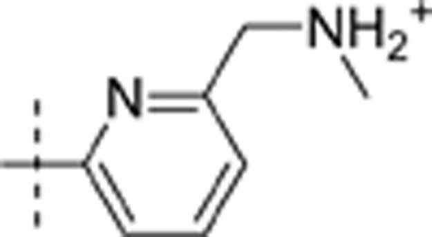 |
6.152 | 1.453 |
| 20 | t-Bu | H | H | 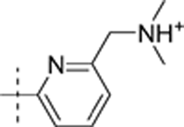 |
6.818 | 1.398 |
| 21 | t-Bu | H | H | 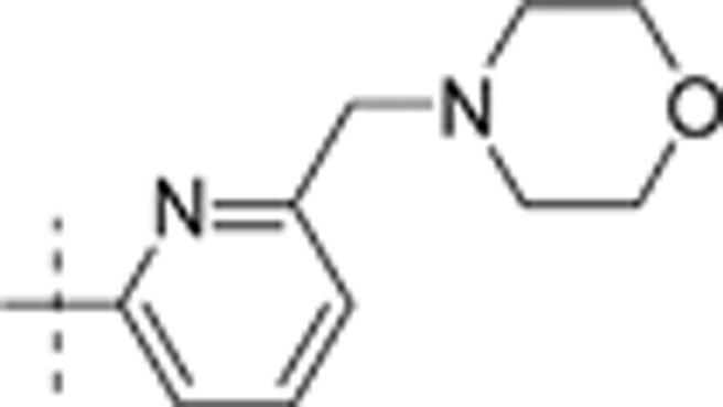 |
6.382 | 1.51 |
| 22 | t-Bu | H | H | 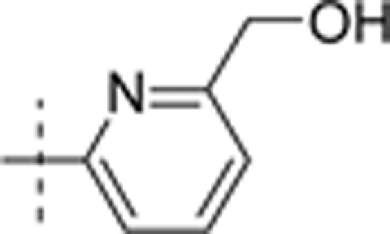 |
5.989 | 0.778 |
| 23 | t-Bu | H | H | 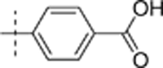 |
5.558 | −0.4 |
| 24 | t-Bu | H | H | 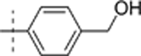 |
5.929 | −0.187 |
| 25 | t-Bu | H | H | 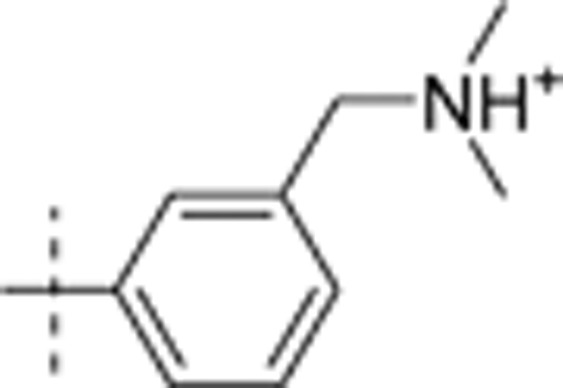 |
7.15 | 1.626 |
| 26 | t-Bu | H | H | 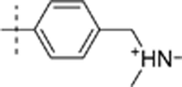 |
6.678 | 0.892 |
| 27 | t-Bu | H | H | 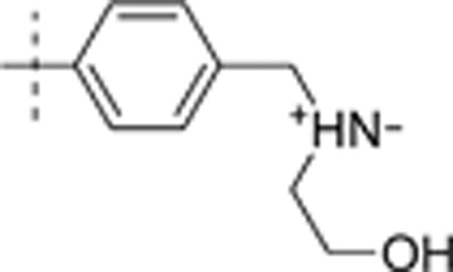 |
7.152 | 1.015 |
| 28 | t-Bu | H | H | 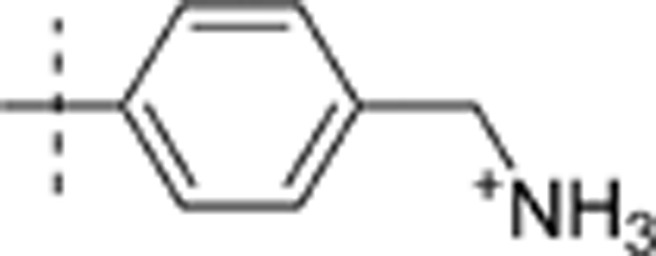 |
7.209 | 1.882 |
| 29 | t-Bu | H | H | 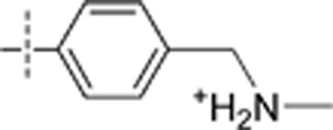 |
6.969 | 1.253 |
| 30 | t-Bu | H | H | 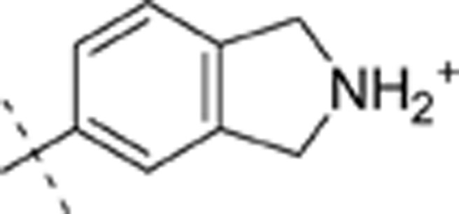 |
6.627 | 0.797 |
| 31 | t-Bu | H | H | 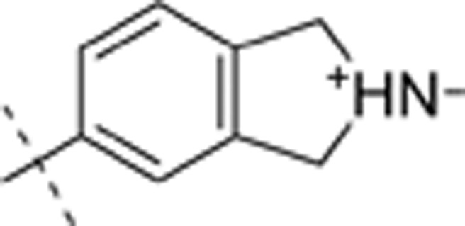 |
6.58 | 1.018 |
| 32 | t-Bu | H | H | 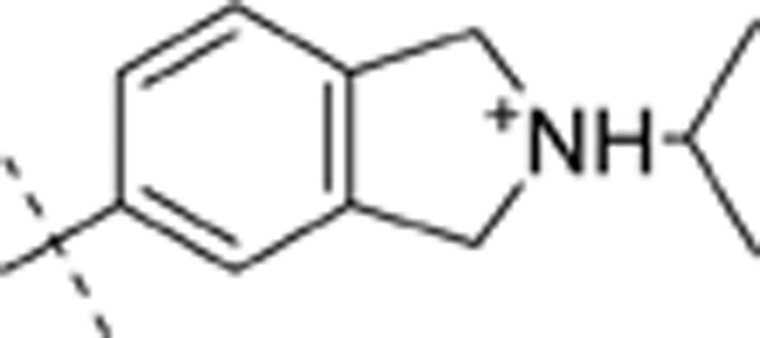 |
6.691 | 1.574 |
| 33 | t-Bu | H | H | 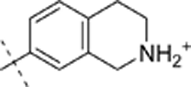 |
7.032 | 0.724 |
| 34 | t-Bu | H | H | 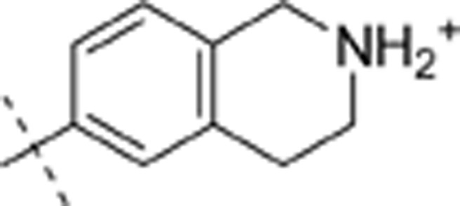 |
6.984 | 1.226 |
| 35 | t-Bu | H | H | 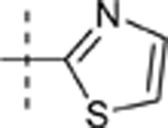 |
6.888 | 0.688 |
| 36 | t-Bu | H | H | 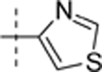 |
5.552 | 0.398 |
| 37 | t-Bu | H | H | 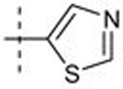 |
6.785 | 0.041 |
| 38 | t-Bu | H | H | 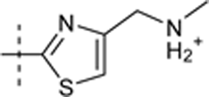 |
7.026 | 1.46 |
| 39 | t-Bu | H | H | 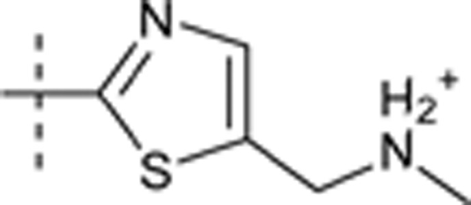 |
6.934 | 0.919 |
| 40 | t-Bu | H | H | 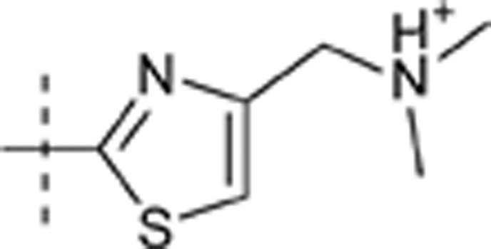 |
6.939 | 1.513 |
| 41 | t-Bu | H | H | 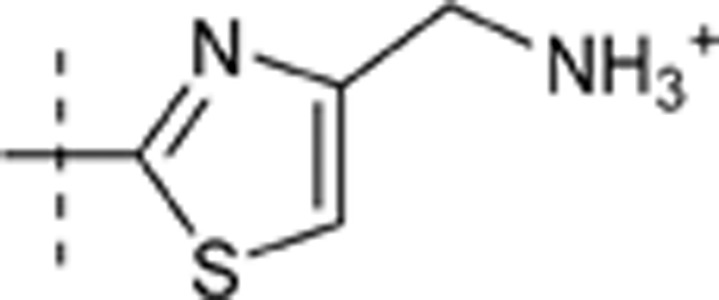 |
6.586 | 0.623 |
| 42 | t-Bu | H | H | 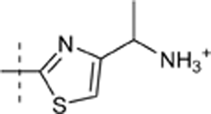 |
7.279 | 1.64 |
| 43 | t-Bu | H | H | 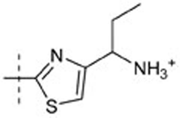 |
6.812 | 1.382 |
| 44 | t-Bu | H | H | 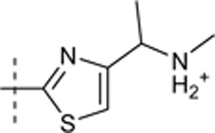 |
7.006 | 1.473 |
| 45 | t-Bu | H | H | 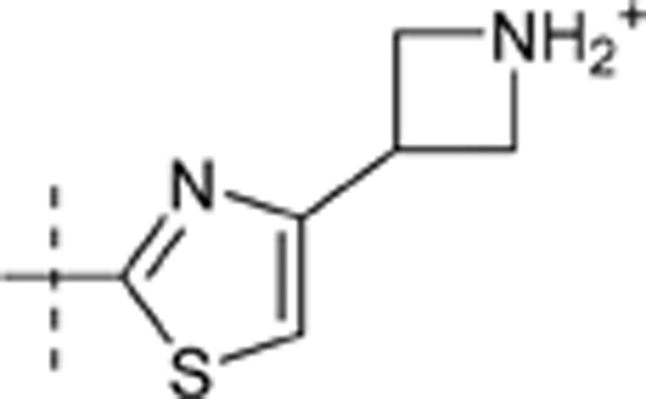 |
6.708 | 1.137 |
| 46 | t-Bu | H | H | 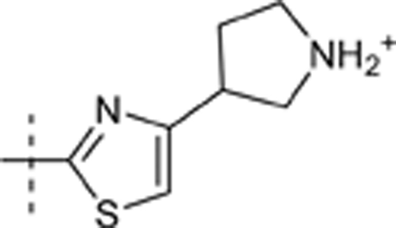 |
6.743 | 1.41 |
| 47 | t-Bu | H | H | 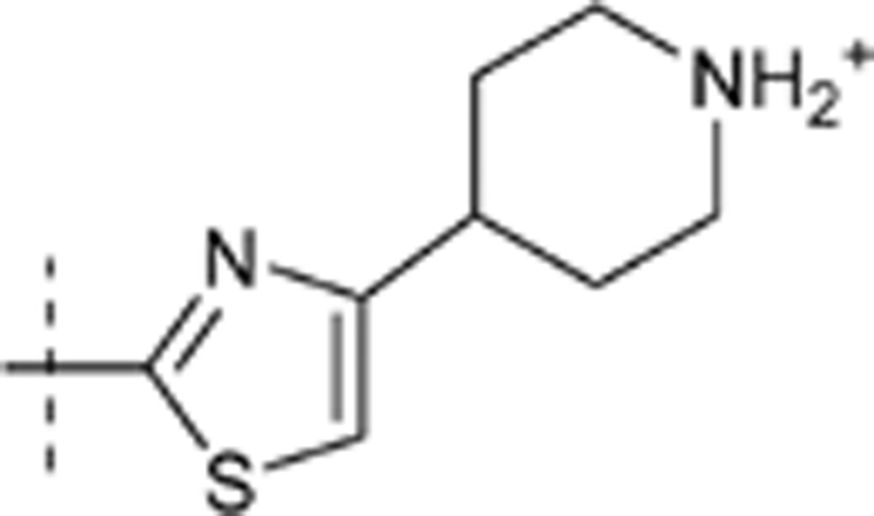 |
7.457 | 2.084 |
| 48 | t-Bu | H | H | 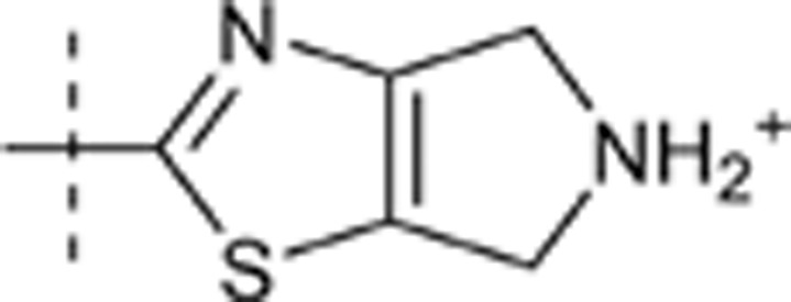 |
7.157 | 0.903 |
| 49 | i-Pr | H | H | 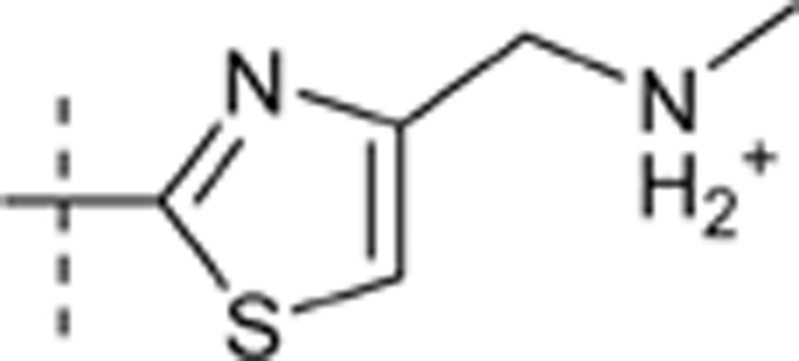 |
6.777 | 1.413 |
| 50 | 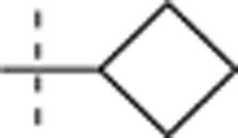 |
H | H | 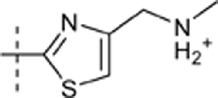 |
6.902 | 1.493 |
| 51 | 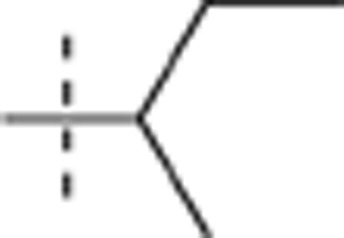 |
H | H | 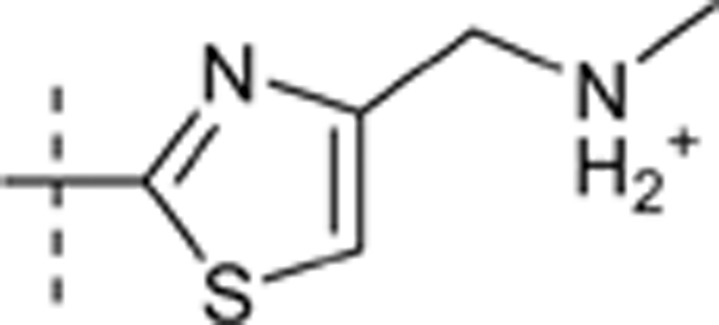 |
7.095 | 1.182 |
| 52 | 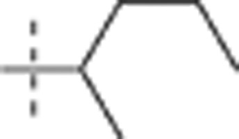 |
H | H | 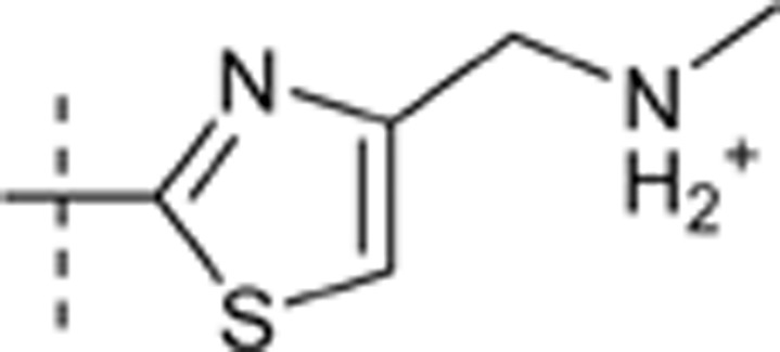 |
7.097 | 1.67 |
| 53 | 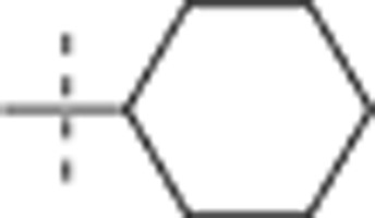 |
H | H | 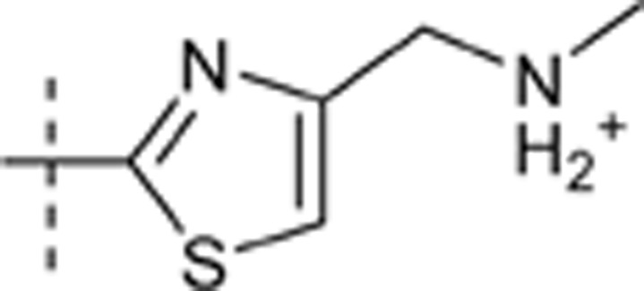 |
7.287 | 1.607 |
| 54 | 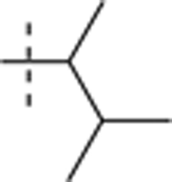 |
H | H | 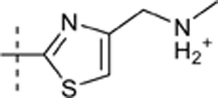 |
7.232 | 1.602 |
| 55 | 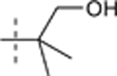 |
H | H | 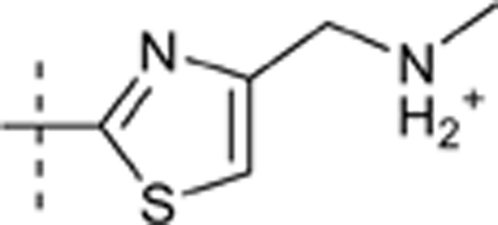 |
6.737 | 1.417 |
| 56 | 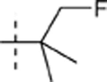 |
H | H | 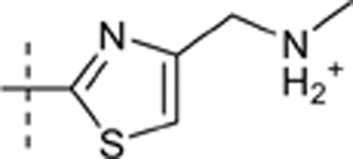 |
6.421 | 1.111 |
| 57 | 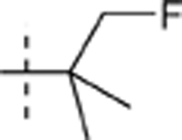 |
H | H | e4r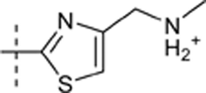
|
6.904 | 1.167 |
Molecular docking
The crystal structure of CDK4 co-crystalized with the ligand is not available. In order to construct the inhibitor located at the active site of CDK4, the X-ray structure of CDK2 complexed with a pyrazolo(4,3-H) quinazoline-3-carboxamide inhibitor (PDB ID:2WXV) was aligned with the CDK4 crystal structure (PDB ID:2W9F) using Align Structures in the Homology module of SYBYL 6.918. The CDK2 inhibitor was then merged into the CDK4 active site, following which it is modified to compound 47, one of the CDK4 inhibitors listed in Table 1. Molecular docking was performed with GOLD (Genetically Optimized Ligand Docking), version 5.019. The active binding site in GOLD docking was defined by selecting residues within 6 Å of the ligand. Examination of the binding site indicated that the side chains of Ile12 and Lys35 of CDK4 assumed sterically unfavorable conformations that would hinder docking of the inhibitors. To address this issue, the side chains of Ile12 and Lys35 were set to flexible mode, whereas the other active site residues were kept rigid. The predicted binding mode provided by Horiuchi et al16 indicated that NH of hydrazone and the nitrogen atom in the pyrimidine ring of these compounds had formed two backbone hydrogen bonds with Val96 (CDK4), which are commonly found in kinase-inhibitor interaction. So two hydrogen-bond constraints between the pyrimidine N and NH of the Val96 backbone, and NH of hydrazone and the backbone O of Val96 were used in GOLD docking. Genetic Algorithm (GA) was applied to identify potentially active binding conformations for the ligand. GoldScore function was used as the fitness function.
Molecular preparation and alignment
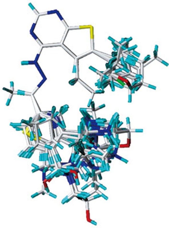
The 3D structures of the 56 compounds were constructed based on the best docked conformation of compound 47 using the SYBYL 6.9 software. Gasteiger-Hückel charges were calculated. Energy minimization using the distance-dependent dielectric function (standard Tripos force field) and Powell method was carried out. A convergence criterion of 0.005 kcal/mol·Å for the conjugate gradient was set. The maximum iterations number was 1000. The molecular alignment is crucial for deriving statistical QSAR and QSSR models. Due to the relative rigidity of the test compounds, ligand-based alignment rule was employed in the present work to derive CoMFA models. All these molecules were aligned on the maximum common substructure using Fit-atom protocol. The superposition of all 57 aligned molecules is shown in Figure 1.
Figure 1.
Molecular alignment of 57 thieno[2,3-d]pyrimidin-4-yl hydrazone analogues.
CoMFA analysis
In the generation of CoMFA models, the aligned molecules were placed in a 3D cubic lattice box (2-Å grid spacing). CoMFA steric and electrostatic fields were calculated by using probe atom (Csp3+1). The computed field energies with the standard cutoffs of 30 kcal/mol were used as independent variables. The pIC50(CDK4) values and log[IC50 (CDK2)/IC50(CDK4)] values from the training set were used as dependent variables to derive 3D-QSAR and 3D-QSSR models, respectively. The leave-one-out (LOO) procedure with a column filtering of 2.0 was employed in the cross-validation to calculate q2 (cross-validated coefficient). The optimum number of components (ONC) optimized by the q2 was used in non-cross-validation. The external validation of the model predictability was performed in the test set. The predictive correlation coefficient r2pred was calculated as described in reference20.
Results and discussion
Molecular docking
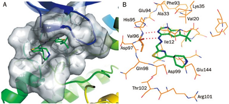
The top-ranked docked conformation of compound 47 in the CDK4 active site is presented in Figure 2. This conformation had the highest Goldscore value. CDK4 active site residues are shown in Van der Waals surface form (Figure 2A) to demonstrate that no steric conflict existed between the ligand and the side chains of Ile12 and Lys35. The hydrogen bond interaction mode is represented in Figure 2B. The ligand was anchored in the ATP-binding pocket by two hydrogen bonds with Val96 in the CDK4 hinge region. One hydrogen bond was formed between the pyrimidine N and the backbone NH of Val96 whereas the other was formed between NH of hydrazone and the backbone oxygen of Val96. This docked conformation was used as a template in CoMFA analysis.
Figure 2.
Binding mode of the compound 47 in the CDK4 active site. The ATP binding pocket of CDK4 is shown in the form of Van der Waals surface, the compound 47 is represented in stick form (A). Hydrogen bond interaction mode of compound 47 with CDK4 (B). The ligand is anchored in the pocket by the two hydrogen bonds formed with the Val96. The two hydrogen bonds are represented by two red dashed lines.
PLS statistical results
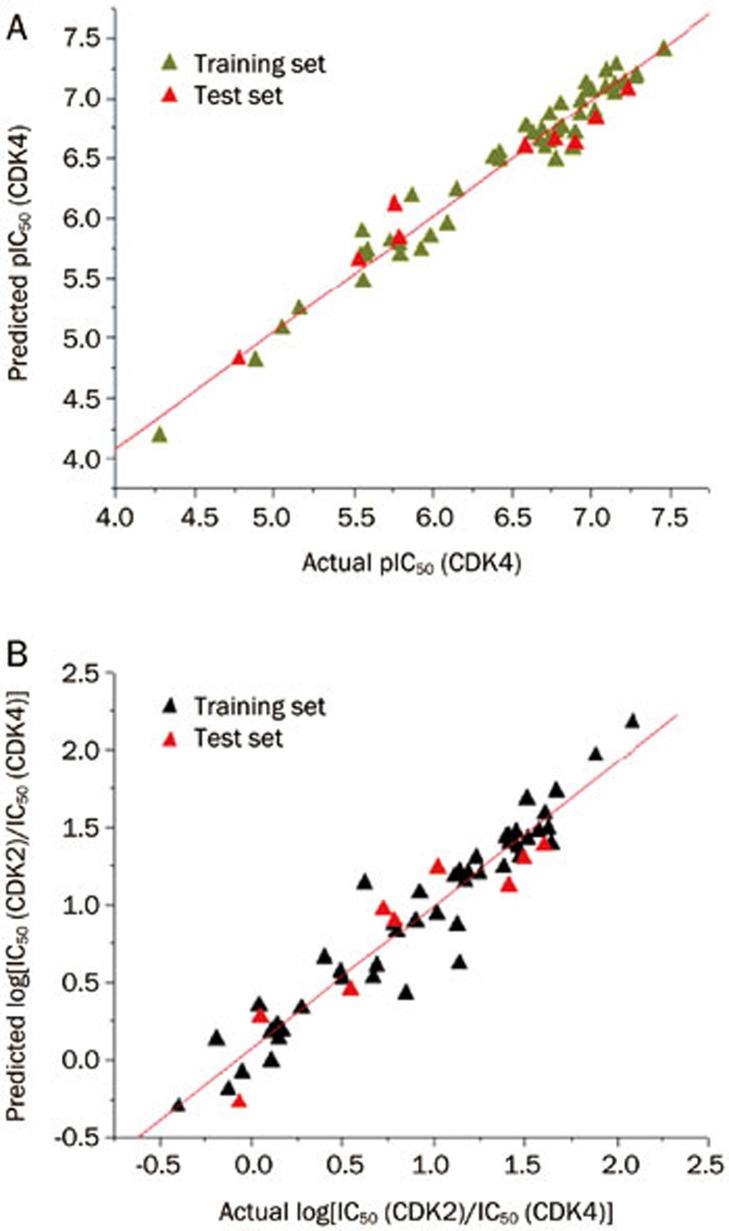
PLS analysis results are reported in Table 2. The derived 3D-QSAR and 3D-QSSR models had conventional r2 values of 0.965 and 0.923, respectively, and q2 of 0.724 and 0.742, respectively. The contributions of the steric and electrostatic fields to the QSAR model were 0.548 and 0.452, respectively. The corresponding values for the QSSR model were 0.444 and 0.556, respectively. External validation with the test set gave r2pred values of 0.945 and 0.863, for QSAR and QSSR respectively. The predicted pIC50 (CDK4) and the log[IC50 (CDK2)/IC50(CDK4)] values from these two models are listed in Table 3. The actual versus predicted values for the two models are shown in Figure 3.
Table 2. The summary analysis of 3D-QSAR and 3D-QSSR models.
| Statistical results | pIC50 (CDK4) | log[IC50 (CDK2)/IC50 (CDK4)] |
|---|---|---|
| q2a | 0.724 | 0.742 |
| ONCb | 6 | 5 |
| r2c | 0.965 | 0.923 |
| F valued | 186.497 | 100.497 |
| SEEe | 0.148 | 0.182 |
| r2predf Field contribution | 0.945 | 0.863 |
| Steric/Electrostatic | 0.548/0.452 | 0.444/0.556 |
aCross-validated coefficient;
bOptimal number of components;
cConventional correlation coefficient;
dFisher test value;
eStandard error of estimate;
fPredictive correlation coefficient.
Table 3. Predicted pIC50 (CDK4) and log[IC50 (CDK2)/IC50 (CDK4)] values and residuals from 3D-QSAR and 3D-QSSR models.
| Compound | pIC50 (CDK4) |
log[IC50 (CDK2)/IC50 (CDK4)] |
||
|---|---|---|---|---|
| Predicted | Residuals | Predicted | Residuals | |
| 1 | 5.732 | −0.148 | 0.191 | −0.025 |
| 2 | 5.241 | −0.082 | −0.079 | 0.031 |
| 3 | 6.482 | 0.299 | 0.425 | 0.42 |
| 4 | 6.477 | −0.056 | 0.528 | 0.141 |
| 5 | 4.191 | 0.085 | −0.189 | 0.064 |
| 6 | 5.076 | −0.023 | 0.52 | −0.018 |
| 7t | 4.827 | −0.052 | −0.276 | 0.212 |
| 8 | 4.812 | 0.074 | −0.005 | 0.113 |
| 9t | 5.647 | −0.119 | 0.449 | 0.098 |
| 10 | 5.813 | −0.081 | 0.18 | −0.075 |
| 11 | 5.946 | 0.147 | 0.224 | −0.086 |
| 12 | 5.696 | 0.103 | 0.33 | −0.058 |
| 13 | 6.182 | −0.311 | 0.141 | 0.008 |
| 14 | 5.686 | −0.147 | 0.563 | −0.07 |
| 15t | 5.834 | −0.04 | 0.273 | −0.2238 |
| 16 | 5.691 | −0.124 | 0.615 | 0.52 |
| 17 | 5.787 | 0.009 | 0.871 | 0.252 |
| 18t | 6.111 | −0.349 | 0.902 | −0.117 |
| 19 | 6.228 | −0.076 | 1.467 | −0.014 |
| 20 | 6.751 | 0.067 | 1.434 | −0.036 |
| 21 | 6.495 | −0.113 | 1.678 | −0.168 |
| 22 | 5.845 | 0.144 | 0.875 | −0.097 |
| 23 | 5.479 | 0.079 | −0.297 | −0.103 |
| 24 | 5.738 | 0.191 | 0.133 | −0.32 |
| 25 | 7.044 | 0.106 | 1.489 | 0.137 |
| 26 | 6.644 | 0.034 | 0.891 | 0.001 |
| 27 | 7.113 | 0.039 | 0.946 | 0.069 |
| 28 | 7.135 | 0.074 | 1.963 | −0.081 |
| 29 | 7.124 | −0.155 | 1.203 | 0.05 |
| 30 | 6.698 | −0.071 | 0.82 | −0.023 |
| 31t | 6.589 | −0.009 | 1.236 | −0.218 |
| 32 | 6.732 | −0.041 | 1.474 | 0.1 |
| 33t | 6.824 | 0.208 | 0.972 | −0.248 |
| 34 | 7.064 | −0.08 | 1.301 | −0.075 |
| 35 | 6.575 | 0.313 | 0.605 | 0.083 |
| 36 | 5.889 | −0.337 | 0.654 | −0.256 |
| 37 | 6.71 | 0.075 | 0.346 | −0.305 |
| 38 | 6.893 | 0.133 | 1.37 | 0.09 |
| 39 | 6.857 | 0.077 | 1.08 | −0.161 |
| 40 | 6.979 | −0.04 | 1.427 | 0.086 |
| 41 | 6.762 | −0.176 | 1.142 | −0.519 |
| 42 | 7.172 | 0.107 | 1.392 | 0.248 |
| 43 | 6.952 | −0.14 | 1.244 | 0.138 |
| 44 | 7.066 | −0.06 | 1.313 | 0.16 |
| 45 | 6.583 | 0.125 | 1.213 | −0.076 |
| 46 | 6.86 | −0.117 | 1.442 | −0.032 |
| 47 | 7.399 | 0.058 | 2.177 | −0.093 |
| 48 | 7.277 | −0.12 | 0.897 | 0.006 |
| 49t | 6.647 | 0.13 | 1.1241 | 0.2889 |
| 50t | 6.616 | 0.286 | 1.298 | 0.195 |
| 51 | 7.086 | 0.009 | 1.204 | −0.022 |
| 52 | 7.227 | −0.13 | 1.725 | −0.055 |
| 53 | 7.194 | 0.093 | 1.584 | 0.023 |
| 54t | 7.078 | 0.154 | 1.382 | 0.22 |
| 55 | 6.634 | 0.103 | 1.396 | 0.021 |
| 56 | 6.54 | −0.119 | 1.187 | −0.076 |
| 57 | 6.703 | 0.201 | 1.157 | 0.01 |
tDenote the test set compounds.
Figure 3.
Correlation between the actual values and predicted values of the 3D-QSAR model (A) and the 3D-QSSR model (B).
3D contour map analyses
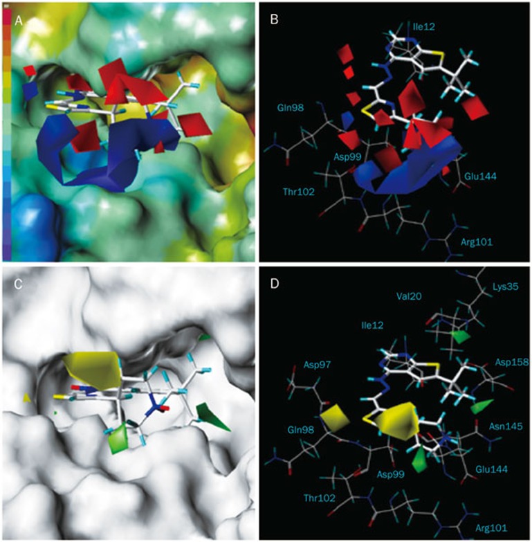
The 3D contour plots graphically interpreting the CoMFA models were generated using the standard STDEV*COEFF field type. The MOLCAD surfaces were calculated for CDK4 with the Fast Connolly method to display the solvent-accessible surface and the electrostatic potential surface. The projection of CoMFA contour maps on to the MOLCAD generated surface maps and the CDK4 active binding site residues, which are presented in Figures 4 and 5, respectively, to aid in the elucidation of the structure-activity and structure-selectivity relationships, respectively. Compound 47 was used as the representative compound for visualization purposes.
Figure 4.
3D-QSAR electrostatic contours plots projected onto the MOLCAD electrostatic potential surface of the CDK4 active binding site for compound 47 (A). Comparison between the electrostatic contours and the active site residues (B). Steric contour plots projected onto the MOLCAD solvent accessible surface map (C). Comparison between the steric contours and the active site residues (D).
Figure 5.
The match of 3D-QSSR electrostatic contours with the CDK4 active site residues (A). The match of steric contours with the active site residues (B).
3D-QSAR contour map analyses
In Figure 4, blue and red contours represent regions where electropositive groups are favored and disfavored for inhibitory activity, respectively. Blue and red colors on the electrostatic potential MOLCAD surface map represent the most negative and most positive electrostatic potentials, respectively. One bulky blue contour surrounded the positively charged piperidine moiety of compound 47 and coincided with a negative region of the active site (Figure 4A), supporting the notion that cationic groups at the R4 position near the side chain of Asp99, Thr102, and Glu144 (Figure 4B) were favorable. In fact, many compounds containing a protonated N in the pyridinyl, phenyl and thiazole rings at this position (Table 1) exhibited higher activities than compounds without electropositive groups. Three extensive red contours near the piperidine ring close to the Ile12 indicated that electropositive groups were not desired in these regions.
Green and yellow contours are indicative of regions where large groups favored and disfavored inhibition, respectively. Likewise, there was a parallel between the steric fields and the CDK4 active site (Figure 4C, 4D). Bulky yellow contour located on the hydrogen atoms of the piperidine moiety of compound 47 were close to the Ile12 (Figure 4D), which coincided with the extensive red contours in the electrostatic contour maps (Figure 4B). The implication was that bulky substituents near the backbone of Ile12 were undesirable. In the case of compound 47, the piperidine moiety had an adequate shape to occupy this site. However, compounds 21, 26, 30, 32, 43, 44 with alkyl groups that extended into the vicinity of this sterically and electrostatically disfavored region, were less active. One yellow contour on the left located in the solvent inaccessible region of ATP binding pocket (Figure 4C) indicated that bulky groups at R3 position near the backbone of Asp97 and Gln98 were unfavorable (Figure 4D). In fact, compound 6 with a methyl group at R3 position was much less active than most compounds with a hydrogen at the same position. The match of the green contour maps with the cavity of the CDK4 active binding site is displayed in Figure 4C and 4D. One contour was located at the solvent accessible region at the entrance of the ATP binding pocket, another was surrounded by the side chains of Val20 and Lys35, and the last was surrounded by backbone of Asn 145 and Asp158. In fact, compounds with cyclohexyl ring (compound 53) and 2,3-dimethylbutyl side chain (compound 54) at R1 position which were orientated toward these two green contours inside the binding pocket were more active than compounds 49, 50, 51, 52 which had smaller groups at R1 position.
3D-QSSR contour map analyses
Electrostatically favorable regions (blue contours) and disfavorable regions (red contours) for CDK4 selectivity are shown in Figure 5A. One large blue contour located at the positively charged piperidine nitrogen of compound 47 coincided with the acidic region surrounded by the side chains of Asp99 and Glu144 in CDK4. In contrast, such interactions were absent in CDK2 as Glu144 (CDK4) was replaced by Gln131 at the CDK2 binding site. In fact, most compounds containing a cationic group at R4 had greater CDK4 selectivity than compounds without a protonated N at the same position. This is attributed to the favorable electrostatic interaction between the positive groups of CDK4 selective inhibitors and Glu144 (CDK4) and the accompanying increase in coulombic energy11.
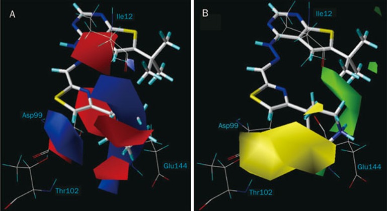
Two bulky red contours in the vicinity of the this large blue contour (Figure 5A) may explain the weak CDK4 selectivity of compounds 7 and 8, which had their t-butyl and cyclopropyl groups oriented toward these electrostatically disfavored regions at R4 position. Compound 5 with an ethyl group at R2 position, near these two red contours was less selective than most of the compounds with H at the same position which indicated that the electropositive groups were not favored at the R2 position.
One blue contour located on the left side of the hydroxyl group of Thr102 (CDK4) suggested that positive groups were desired in this region. In the case of CDK2, the δ-amino group of Lys89 projected in this region11. In fact, compounds with a negatively charged carboxylate (compound 23) and hydroxymethyl group (compound 24) at R4 were more selective for CDK2 than CDK4. This indicated that negatively charged groups were poorly tolerated at this position and would not serve to enhance CDK4 selectivity. In fact, compounds with positively charged substituents at the same position of the phenyl ring, exhibited greater CDK4 selectivity, as seen from compound 28 which had an aminomethyl side chain at R4. Very likely, the unfavorable electrostatic repulsion between the two NH3+ groups of compound 28 and Lys89 (CDK2), and the favorable H bond formed between the NH3+ group of compound 28 and the hydroxyl group of Thr102 (CDK4) enhanced CDK4 selectivity.
Sterically favorable regions (green contours) and disfavorable regions (yellow contours) for CDK4 selectivity are shown in Figure 5B. One green contour surrounding the piperidine moiety of compound 47 suggested that large substituents were favored in the vicinity of the side chains of Asp99 and backbone of Glu144. It would explain the greater CDK4 selectivity of compounds (38, 40, 44, 46, 49–56) which had alkyl amino groups extending into this green region. In contrast, compounds (35, 36, 37) that do not have alkyl amino substitutions at the thiazole ring were poorly selective for CDK4. One bulky yellow contour positioned on the left side near the Thr102 indicated that the large substituents were unfavorable in this region. This would account for the less selective inhibitors with the carboxyl (compound 23) and hydroxymethyl (compound 24) groups orientated towards this contour.
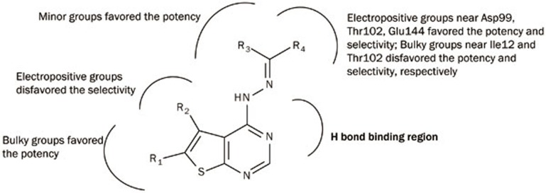
In conclusion, we have herein reported statistically reliable 3D-QSAR and 3D-QSSR models derived from thieno[2,3-d]pyrimidin-4-yl hydrazone analogues by using CoMFA analysis. These models had high predictive power (QSAR model: q2=0.724; QSSR model: q2=0.742), and were validated by an external test set. CoMFA contour maps that were in good agreement with the CDK4 active site identified the vital interactions between key residues and major substituent groups on the inhibitors. Structure relationship revealed by these models and docking studies are summarized in Figure 6. Bulky groups at R1 position would improve the inhibitory activity but large groups at R3 position would have the opposite effect. Appropriate bulky positively-charged groups at R4 position would increase not only the activity but also the specificity for CDK4. The insight obtained from these models would greatly assist and guide drug design strategies aimed at uncovering potent and selective CDK4 inhibitors.
Figure 6.
Structural relationships as revealed by 3D-QSAR and 3D-QSSR models and docking studies.
Author contribution
Dr Hai-xiao JIN and Prof Xiao-jun YAN designed the research and revised the manuscript; Bao-qin CAI conducted the research and wrote the manuscript; Peng ZHU and Gui-xiang HU helped write the paper.
Acknowledgments
This work was supported by Natural Science Foundation of Ningbo (2010A610025); Zhejiang Marine Biotechnology Innovation Team (ZMBIT) (2012R10029, 2010R50029-3); Subject Project of Ningbo University (xkc11003); Scientific Research Fund of Ningbo University (XYL11014); KC WONG Magna Fund in Ningbo University; Ningbo Marine Algae Biotechnology Team (2011B81007).
References
- Malumbres M, Barbacid M. Mammalian cyclin-dependent kinases. Trends Biochem Sci. 2005;30:630–41. doi: 10.1016/j.tibs.2005.09.005. [DOI] [PubMed] [Google Scholar]
- Malumbres M, Harlow E, Hunt T, Hunter T, Lahti JM, Manning G, et al. Cyclin-dependent kinases: a family portrait. Nat Cell Biol. 2009;11:1275–6. doi: 10.1038/ncb1109-1275. [DOI] [PMC free article] [PubMed] [Google Scholar]
- Morgan DO. Cyclin-dependent kinases: engines, clocks, and microprocessors. Annu Rev Cell Dev Biol. 1997;13:261–91. doi: 10.1146/annurev.cellbio.13.1.261. [DOI] [PubMed] [Google Scholar]
- An H, Beckmann M, Reifenberger G, Bender H, Niederacher D. Gene amplification and overexpression of CDK4 in sporadic breast carcinomas is associated with high tumor cell proliferation. Am J Pathol. 1999;154:113–8. doi: 10.1016/S0002-9440(10)65257-1. [DOI] [PMC free article] [PubMed] [Google Scholar]
- Schmidt EE, Ichimura K, Reifenberger G, Collins VP. CDKN2 (p16/MTS1) gene deletion or CDK4 amplification occurs in the majority of glioblastomas. Cancer Res. 1994;54:6321–4. [PubMed] [Google Scholar]
- Khatib ZA, Matsushime H, Valentine M, Shapiro DN, Sherr CJ, Look AT. Coamplification of the CDK4 gene with MDM2 and GLI in human sarcomas. Cancer Res. 1993;53:5535–41. [PubMed] [Google Scholar]
- Malumbres M, Barbacid M. Is cyclin D1-CDK4 kinase a bona fide cancer target. Cancer Cell. 2006;9:2–4. doi: 10.1016/j.ccr.2005.12.026. [DOI] [PubMed] [Google Scholar]
- Kamb A. Cell-cycle regulators and cancer. Trends Genet. 1995;11:136–40. doi: 10.1016/s0168-9525(00)89027-7. [DOI] [PubMed] [Google Scholar]
- Liggett W, Sidransky D. Role of the p16 tumor suppressor gene in cancer. J Clin Oncol. 1998;16:1197–206. doi: 10.1200/JCO.1998.16.3.1197. [DOI] [PubMed] [Google Scholar]
- Honma T, Yoshizumi T, Hashimoto N, Hayashi K, Kawanishi N, Fukasawa K, et al. A novel approach for the development of selective Cdk4 inhibitors: library design based on locations of Cdk4 specific amino acid residues. J Med Chem. 2001;20:4628–40. doi: 10.1021/jm010326y. [DOI] [PubMed] [Google Scholar]
- McInnes C, Wang S, Anderson S, O'Boyle J, Jackson W, Kontopidis G, et al. Structural determinants of CDK4 inhibition and design of selective ATP competitive inhibitors. Chem Biol. 2004;11:525–34. doi: 10.1016/j.chembiol.2004.03.022. [DOI] [PubMed] [Google Scholar]
- Fry DW, Bedford DC, Harvey PH, Fritsch A, Keller PR, Wu Z, et al. Cell cycle and biochemical effects of PD 0183812. A potent inhibitor of the cyclin D-dependent kinases CDK4 and CDK6. J Biol Chem. 2001;276:16617–23. doi: 10.1074/jbc.M008867200. [DOI] [PubMed] [Google Scholar]
- Barvian M, Boschelli D, Cossrow J, Dobrusin E, Fattaey A, Fritsch A, et al. Pyrido[2,3-d]pyrimidin-7-one inhibitors of cyclin-dependent kinases. J Med Chem. 2000;43:4606–16. doi: 10.1021/jm000271k. [DOI] [PubMed] [Google Scholar]
- Cramer RD, Patterson DE, Bunce JD. Comparative molecular field analysis (CoMFA). 1. Effect of shape on binding of steroids to carrier proteins. J Am Chem Soc. 1988;110:5959–67. doi: 10.1021/ja00226a005. [DOI] [PubMed] [Google Scholar]
- Horiuchi T, Chiba J, Uoto K, Soga T. Discovery of novel thieno[2,3-d]pyrimidin-4-yl hydrazone-based inhibitors of cyclin D1-CDK4: synthesis, biological evaluation, and structure-activity relationships. Bioorg Med Chem Lett. 2009;19:305–8. doi: 10.1016/j.bmcl.2008.11.090. [DOI] [PubMed] [Google Scholar]
- Horiuchi T, Nagata M, Kitagawa M, Akahane K, Uoto K. Discovery of novel thieno[2,3-d]pyrimidin-4-yl hydrazone-based inhibitors of cyclin D1-CDK4: synthesis, biological evaluation and structure-activity relationships. Part 2. Bioorg Med Chem. 2009;17:7850–60. doi: 10.1016/j.bmc.2009.10.039. [DOI] [PubMed] [Google Scholar]
- Horiuchi T, Takeda Y, Haginoya N, Miyazaki M, Nagata M, Kitagawa M, et al. Discovery of novel thieno[2,3-d]pyrimidin-4-yl hydrazone-based cyclin-dependent kinase 4 inhibitors: synthesis, biological evaluation and structure-activity relationships. Chem Pharm Bull (Tokyo) 2011;59:991–1002. doi: 10.1248/cpb.59.991. [DOI] [PubMed] [Google Scholar]
- SYBYL. Version 6.9. St Louis, MO: Tripos Associates; 1999.
- Verdonk ML, Cole JC, Hartshorn MJ, Murray CW, Taylor RD. Improved protein-ligand docking using GOLD. Proteins. 2003;52:609–23. doi: 10.1002/prot.10465. [DOI] [PubMed] [Google Scholar]
- Roy PP, Roy K. On some aspects of variable selection for partial least squares regression models. QSAR Comb Sci. 2008;27:302–13. [Google Scholar]


