Abstract
Assuring cell adhesion to an underlying biomaterial surface is vital in implant device design and tissue engineering, particularly under circumstances where cells are subjected to potential detachment from overriding fluid flow. Cell-substrate adhesion is a highly regulated process involving the interplay of mechanical properties, surface topographic features, electrostatic charge, and biochemical mechanisms. At the nanoscale level the physical properties of the underlying substrate are of particular importance in cell adhesion. Conventionally, natural, pro-adhesive, and often thrombogenic, protein biomaterials are frequently utilized to facilitate adhesion. In the present study nanofabrication techniques are utilized to enhance the biological functionality of a synthetic polymer surface, polymethymethacrylate, with respect to cell adhesion. Specifically we examine the effect on cell adhesion of combining: 1. optimized surface texturing, 2. electrostatic charge and 3. cell adhesive ligands, uniquely assembled on the substrata surface, as an ensemble of nanoparticles trapped in nanowells. Our results reveal that the ensemble strategy leads to enhanced, more than simply additive, endothelial cell adhesion under both static and flow conditions. This strategy may be of particular utility for enhancing flow-resistant endothelialization of blood-contacting surfaces of cardiovascular devices subjected to flow-mediated shear.
Keywords: cell adhesion, ensemble surface, detachment resistance, nanopatterning, nanotextured surface
1. Introduction
Studies of engineered cell-material interactions at the subcellular, nanoscale level have provided important information regarding cell attachment and proliferation behavior. Micro- and nano-scale technologies combined with bioactive ligands have been demonstrated to facilitate cell adhesion, guide migration, and affect proliferation.[1–4] Furthermore, nanoscale architecture can regulate the structure and function of cells[5,6] as well as cellular attachment and proliferation on substrates with spatial cues and physical constraints.[7–9] Such knowledge has been gained from numerous cell patterning strategies including those utilizing bioadhesive molecules or modified polymers via contact printing and photolithography; or through treatment of bioinert surfaces using plasma lithography to improve and enhance cell adhesion.[2,3,10–15] Despite significant advances in modifying surfaces for cellular attachment, the achievement of confluent and aligned growth of endothelial cells under physiologically significant wall shear stress has proven difficult.[16–18] In the present study we sought to develop a method that would enhance cellular adhesion under flow conditions on synthetic polymer surfaces, without reliance on pro-adhesive protein biomaterials, which are often thrombogenic, e.g. collagen. To achieve this, we examined the efficacy of an additive strategy combining substrata topographic alteration, electrostatic charge and biochemical ligands, all uniquely incorporated as an ensemble of charged, ligand-bearing nanoparticles entrapped in arrays of nanowells. As such, the ensemble provides a topographically more favorable surface with complexity and enhanced cell accessible surface area, there is an element of charge exposure, which appears favorable to adhesion, and finally there are ligands (RGD) which incorporates integrin-mediated adhesion. Overall, the ensemble capitalizes on multiple mechanisms to enhance adhesion. We applied methods of electron beam lithography (EBL) and size-dependent self-assembly (SDSA) to fabricate arrays of nanowells allowing entrapment and retention of charged nanoparticles, covalently conjugated with a cell adhesive ligand, GRGDSPK (RGD peptide). Creation of an ensemble of nanoparticles trapped in nanowells is a difficult task and have not been demonstrated for cell-biomaterial interaction studies, to the best of our knowledge. We have previously characterized and reported on size-dependent self-assembly (SDSA),[19] demonstrating the ability of this approach to provide high resolution nanoscale features with good saturation and retention of nanoparticles.
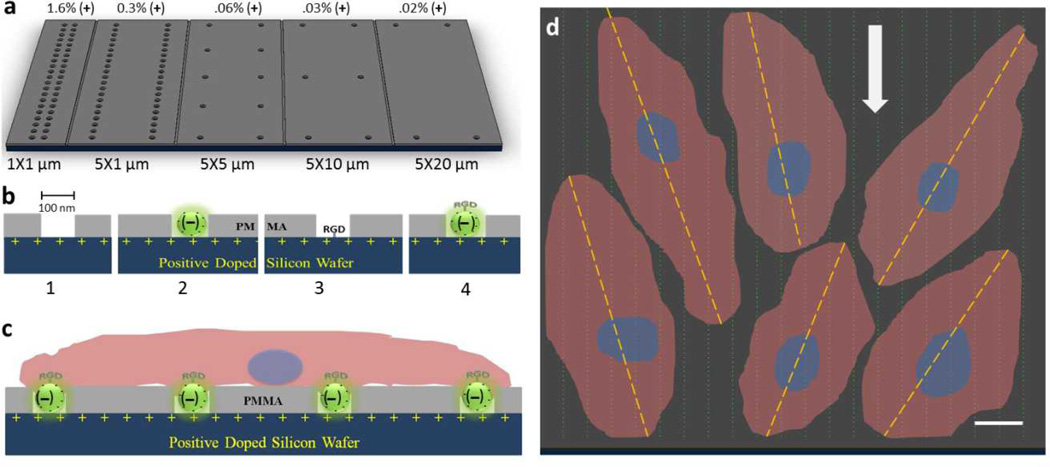
In the present study the overall goal was to transform a relatively bio-inert surface, i.e. polymethyl methacrylate (PMMA), into a pro-adhesive surface suitable for the growth and maintenance of human umbilical vascular endothelial cells (HUVECs) under flow conditions. We hypothesized that the combination of surface texturing, positive electrostatic charge and bioadhesive ligands, uniquely applied to underlying cell substrata, through the development of an array of nanowells with entrapped nanoparticles, would synergistically provide greater cell adhesion and retention, particularly under flow conditions. To test this hypothesis, we first examined the effect of surface texturing alone on endothelial cell adhesion (Figure 1A). We then examined the effect of adding charged nanoparticles and RGD bioadhesive peptides, utilizing entrapped nanoparticles in nanowell arrays, on cell attachment and proliferation (Figure 1B,C). Finally, we compared the ability of this ensemble surface to retain endothelial cells, when subjected to flow, to that of unmodified surfaces and investigated the adherent cell orientation relative to the direction of flow (Figure 1D).
Figure 1.
Nanowell distribution on p-doped silicon substrata and cell adhesion model. A) Surface view of nanowell array in different x-y spacing. The percent of positive charge exposed from well patterns is indicated above the figure. B) Incorporating components leading to the final ensemble surface. 1. plain well pattern (wells) as surface textures, 2. trapped carboxylated nanoparticles ((−)beads in wells), 3. well pattern with RGD peptide (pI = 8.75; RGD in wells), and 4. RGD-conjugated nanoparticles in wells (RGD-(−)beads in wells). C) Side view schematic of endothelial cell attachment on ensemble nanotextured surface, RGD-(−)beads in wells. D) Schematic of cells attachment and alignment. Dashed line indicates long axis of endothelial cells tethered to measure the angle of alignment relative the direction of flow (bold arrow). The scale bar is 10 µm.
2. Results
2.1. Nanowells Enhance HUVEC Adhesion on PMMA Surface
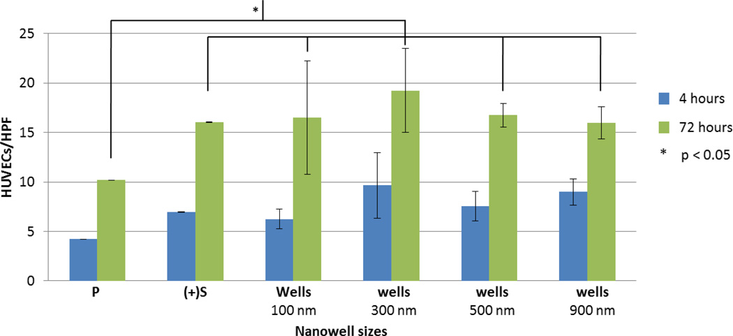
As a first step we examined the effect of the addition of nanowells, as a surface texturing feature, to a PMMA on HUVEC adhesion. A range of nanowell size and spatial (x-y spacing) configuration (without added nanoparticles) was studied. As the density of a nanopattern may influence cell adhesion,[3,4,8] we first tested wells of 100 nm that were separated by 1×1, 5×1, 5×5, 5×10, and 5×20 µm2 in the x-y directions. The maximum well spacing in the x-direction was confined to 5 µm due to the limitation of EBL. We selected a nanoscale well size, i.e. 100 nm, as previous studies by Lehnart et al.[20] and Girard et al.[21] suggested that geometric confinement of 58–100 nm are optimal dimensions for integrin-mediated cell adhesion. Adding nanowell features in all cases led to enhanced adhesion compared to non-textured PMMA (P) alone (p = 5.8×10⁻⁸) (Figure 2). There was also a trend toward increased adhesion on P surfaces with nanowell features compared to the boron-doped (p-doped) silicon surface alone ((+)Si). Of the specific nanowell patterns tested, 5 µm × 1 µm spacing appeared most favorable for HUVECs adhesion, when compared to (+)Si, after 72 hours of cell culture (p = 0.02). We utilized this spacing pattern for all subsequent experiments below.
Figure 2.
The effect of different configurations of well patterns on HUVEC adhesion without nanoparticles or adhesive ligand. HUVEC adhesion as a function of nanowell patterns at different x-y spacing. At 4 hours, nanowell patterns of 5×1 µm2 promote significantly more HUVECs to be attached than any other spacing configuration including control surface (P = spin-coated PMMA on silicon wafer, (+)Si = basal p-doped silicon). At 72 hours of incubation, HUVECs appear to be most attracted to nanowell patterns separated at 5×1 µm2. This observation is insignificant when compared with other patterns of different spacing but highly significant when compared to the (+)Si (p = 0.02) and P surfaces (p = 5.8×10⁻⁸). HUVECs/HPF is the number of HUVECs per high power field (HPF) of a 60× microscope.
2.2. Addition of Individual Surface Features on HUVEC Adhesion – Building the Ensemble Surface
As a next step we determined whether adding additional pro-adhesive elements, i.e. surface charge, charged nanoparticles (a.k.a. beads) and a bioadhesive ligand (Figure 3), would act synergistically to further enhance the adhesion of HUVECs.
Figure 3.
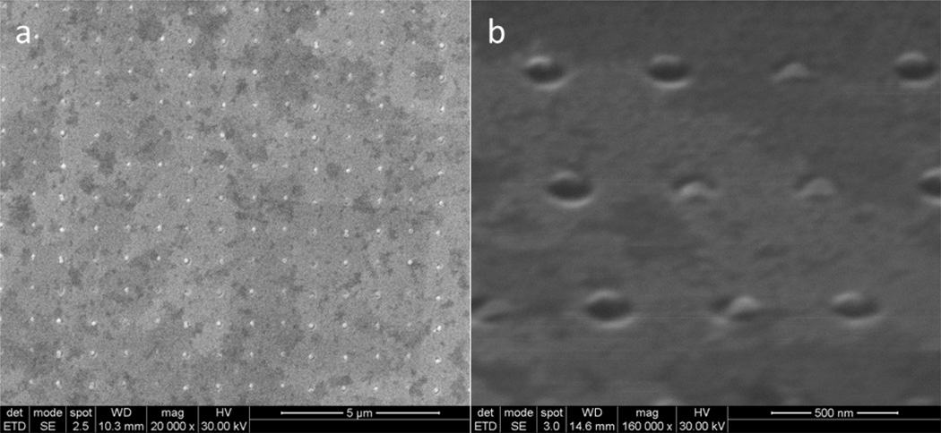
Saturation of nanoparticles on etched wells. A) 100 nm carboxylated (−) charged nanoparticles are trapped inside the nanowells, showing high degree of resolution, controllability, and saturation. These wells are separated by 500 nm in x and y direction. Note that the surface was not uniformly coated with platinum gold. B) Higher magnification of the array under 75° tilt showing nanoparticles being trapped in the well.
2.2.1. Surface Charge
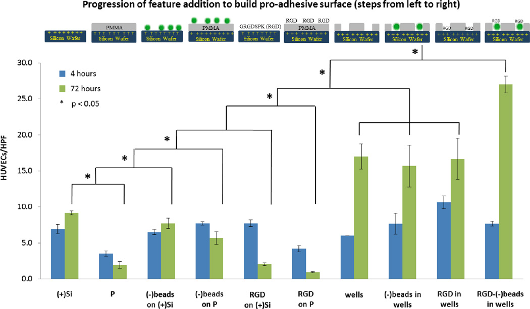
We first examined the effect on HUVEC adhesion of provision of a full, evenly charged surface (positive charge, with resistivity = 16 Ω-cm and charge density = 6.73×10⁻⁵ C/µm2) to that of the neutral PMMA surface. We observed that the (+)Si substratum, being a hydrophilic surface, promoted significantly greater cell attachment than the hydrophobic P surface after 72 hours of culture (Figure 4) (9 ± 1 vs. 2 ± 1, p = 5.6×10⁻¹³).
Figure 4.
Comparative effect of adding features to an underlying p-doped silicon surface using individual adhesive elements to enhance HUVEC adhesion. A 5×1 µm2 nanowell patterned surface of 100 nm relative well size was used to trap nanoparticles and RGD peptides, thereby creating an ensemble nanotextured surface to better enhance HUVECs adhesion. The study here was under static condition. From the very bottom, the hydrophilic p-doped silicon substratum ((+)Si) promotes more cell attachment than the PMMA surface (P). Meanwhile, when the negatively charged nanoparticles were immobilized randomly on the silicon ((−)beads on (+)Si) and PMMA surfaces ((−)beads on P), there is a slight increase in cell adhesion on (−)beads on (+)Si but not for (−)beads on P. When RGD peptides were passively added on silicon (RGD_on_(+)Si) and PMMA surfaces (RGD on P), we did not see any increase in cell adhesion. We hypothesize that the RGD peptides act as a competitive ligand for adhesion or an inhibitor to binding to RGD sequences in serum-derived matrix proteins. Next, we investigated cells on well patterns (wells), well patterns that trapped nanoparticles ((−)beads in wells), and well patterns that trapped RGD peptides (RGD in wells). After 72 hours, dissimilarities among them were not found but double in the number of cells when compared to (+)Si, (−)beads on (+)Si, and (−)beads on P. When (+)Si, P, wells, and RGD-conjugated nanoparticles were combined to make the ultimate pro-adhesive surface (RGD-(−)beads in wells), cell adhesion was synergistically enhanced by three-fold when compared to on (+)Si, (−)beads on (+)Si, and (−)beads on P at 72 hours. HUVECs/HPF is the number of HUVECs per high power field (HPF) of a 60× microscope.
2.2.2. Charged Nanoparticles
We next examined charge provided in a localized fashion via addition of charged nanoparticles. Negatively charged polystyrene nanoparticles ((−)beads), when added randomly on top of a (+)Si surface, i.e. (−)beads on (+)Si (8 ± 1 vs. 9 ± 1, p = 0.96 at 72 h), or on a P surface, i.e. (−)beads on P (6 + 1 vs. 2 ± 1, p = 0.001), did not enhance cell adhesion when compared to (+)Si (Figure 4). This lack of enhanced adhesion may relate to the fact that free nanoparticles are mobile, and negatively charged, both properties which are anti-adhesive for cells attachment and stabilization on a surface.
Nanotexturing of a PMMA layer over p-doped silicon allows the formation of a neutral surface with defined regions of positive charge, spatially contained to the base of the nanowell, i.e. the regions of exposed (+)Si substratum (Figure 1B). This configuration is advantageous in that it allows creation of a composite surface through facilitated self-assembly. Taking advantage of this underlying positively charged silicon surface, we then added negatively charged nanoparticles (carboxylated polystyrene) to create a self-assembled, complex surface. The established 5 µm × 1 µm pattern of 100 nm wells (wells) served as our test textured surface to trap nanoparticles. Enhanced intra-well retention of nanoparticles was achieved using a vibrational droplet manipulator[19] as described in the method (Figure 3, Supporting Information 1). Polystyrene nanoparticles were typically found trapped inside nanowells, with a high degree of saturation and spatial resolution. Nanoparticles were found to protrude about 20 nm above the PMMA surface (Figure 3B), providing additional surface topography and complexity.
The addition of nanoparticles to wells ((−)beads in wells), i.e. the trapped particle-nanowell composite surface, enhanced adhesion of HUVECs compared to that achieved on PMMA alone (16 ± 3 vs. 2 ± 1, p = 0.02 at 72 h) or Si wafer alone (16 ± 3 vs. 9 ± 1, p = 0.08 at 72 h) (Figure 4). However, HUVEC adhesion on the trapped particle-nanowell composite was similar to that achieved on wells. Despite the similarity in adhesion observed between these surfaces the advantage the particle-nanowell composite surface offers is that it provides yet another means for potential synergistic cell adhesion. Individual nanoparticle beads, in addition to having surface charge for surface self-assembly may also be conjugated or otherwise modified to locally present or deliver a drug, peptide or other moiety that is pro-adhesive. By virtue of trapping and retention of nanoparticles locally in nanowells, this allows the spatial tailoring of a surface to provide a means for focused application of pro-adhesive ligands. We studied this possibility with pro-adhesive RGD peptides conjugated to nanoparticles (see below).
2.2.3. RGD peptides
Free RGD peptides added to either PMMA or Si surfaces i.e. RGD on P, or RGD on (+)Si, did not result in an enhancement of HUVEC adhesion. In fact at 72 hours a reduction in adhesion was observed (Figure 4). This reduction may be due to the possible action of free RGD as a competitive ligand for adhesion, or an inhibitor of binding, to native RGD sequences in serum-derived matrix proteins.[23,24] Notably, RGD added to nanowells (RGD in wells) led to enhanced adhesion compared to RGD on P (17 ± 3 vs. 1 ± 1, p = 0.02 at 72 h) or RGD on (+)Si (17 ± 3 vs. 2 ± 1, p = 0.02 at 72 h) but the level of adhesion was found to be comparable to wells, and (−)beads in wells suggesting that under our studied test conditions, nanotexture appears to dominate the contribution of the adhesive ligand (Figure 4).
In contrast when RGD-conjugated nanoparticles, affixed to the surface via charge-mediated entrapment in nanowells, were examined a very significant increase in HUVEC adhesion was observed (Figure 4). Compared to PMMA alone or p-doped silicon alone, a 1400% and 300% increase in adhesion was noted, respectively (27 ± 1 vs. 2 ± 1, p = 0.0003 and 27 ± 1 vs. 9 ± 1, p = 0.001, both at 72 h). This major increase in adhesion was greater than that observed with the addition of any pro-adhesive feature examined in this investigation. When compared to nanotexturing, i.e. wells alone, a major increase in adhesion was observed as well, with a 160% increase noted (p = 0.006).
2.4. Effect of Ensemble Surface on the Resistance of HUVEC to Detachment When Subjected to Flow
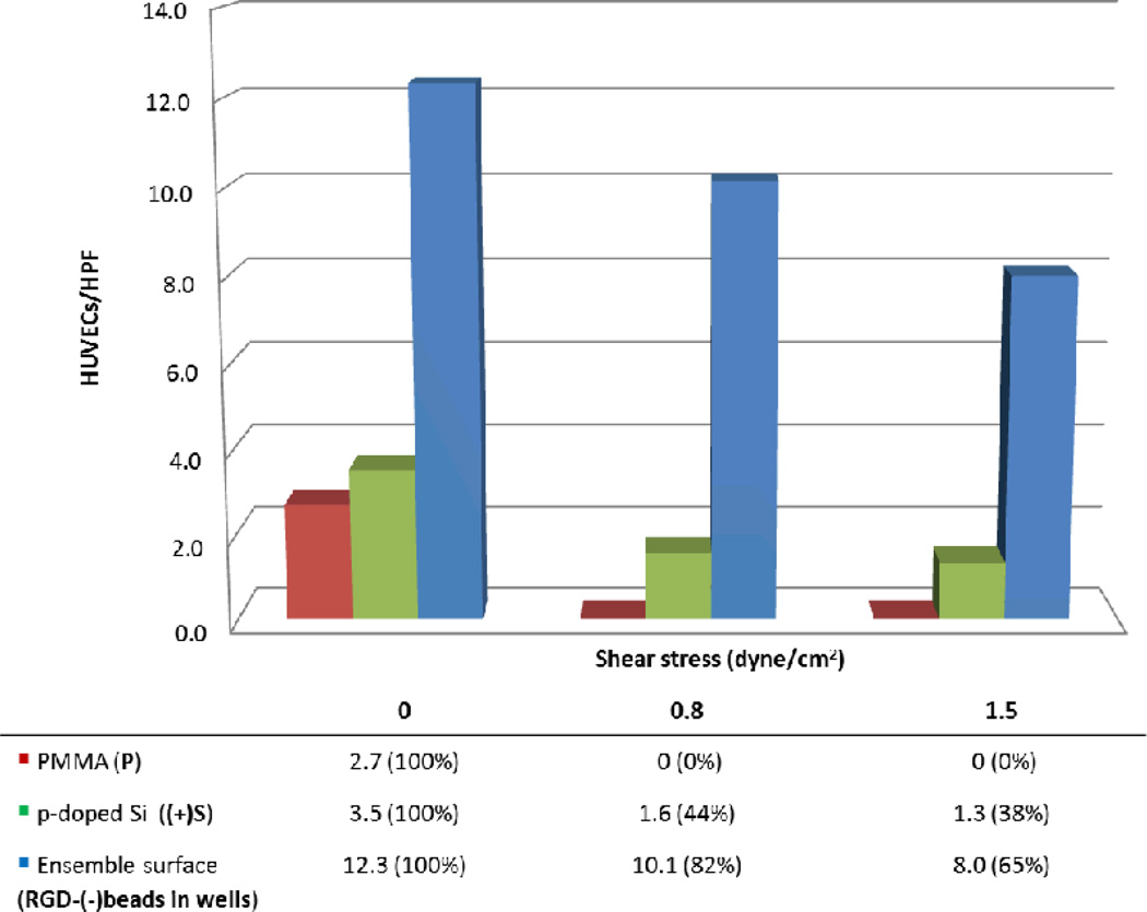
When compared to control PMMA and p-doped Si surfaces, the ensemble surface provided greater resistance to HUVEC detachment when subjected to overflowing fluid flow. In fact, our ensemble RGD-(−)beads in wells surface retained 82% and 65% of HUVECs under 0.8 dyne/cm2 and 1.5 dyne/cm2 respectively (Figure 5); while (+)Si surface retained only about 44% and 38% of cells respectively. Most importantly, we found that our proadhesive surface led to retention of adherent endothelial cells when subjected to wall shear stress, a critical feature for successful endothelialization of cardiovascular implants such as synthetic grafts and stents.
Figure 5.
Resistance to detachment with ensemble nanotextured surface. HUVECs were seeded and subjected to different shear stress. After 24 hours, cells could not be found on the PMMA surface (P), while about 44% of HUVECs were retained by the hydrophilic p-doped Si surface ((+)Si). Under a much greater wall shear stress, about 65% of HUVECs on the ensemble nanotextured surface (RGD-(−)beads in wells) were resistant to flow whereas only 38% of cells on (+)Si, suggesting that this ensemble nanotextured surface can enhance cell adhesion and withstand shear stress.
2.5. The Effect of the Ensemble Surface on the Orientation of HUVEC
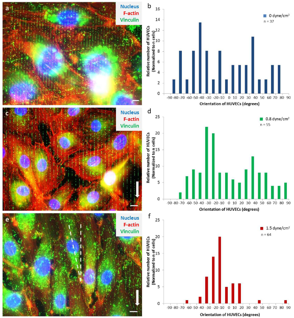
Using our ensemble surface, we examined the effect of wall shear stress on the orientation and alignment of HUVECs adherence. We first examined the orientation of HUVECs under static conditions. The angle of a given cell, with respect to the y-axis (longitudinal axis of the nanowell pattern), was determined. The majority of endothelial cells were found to be oriented randomly (Figure 6A,B). Next, we assessed the orientation of HUVECs under flow (parallel to 5 µm × 1 µm pattern, as shown in Figure 1D and Figure 6C,E). Endothelial cells were seeded on the proadhesive surface for 24 hours and were then subjected to wall shear stress (2 levels: 0.8 and 1.5 dyne/cm2). Under flow conditions, we observed HUVECs aligned their cell centroid in response to the y-axis. With wall shear stress of 0.8 dyne/cm2, most endothelial cells after 36 hours of incubation, were predominantly oriented between −20° to −30° (Figure 6C,D) where 0° is the vector of the y-axis. When cells were subjected to greater wall shear stress (1.5 dyne/cm2), they were notably elongated, with orientation more parallel to the y-axis, mostly at −10° to −30° (Figure 6E,F).
Figure 6.
The effect of different shear stress conditions in relation to the orientation of HUVECs. A) A superimposed image of HUVECs that is not exposed to shear stress has cells in random orientation. B) Distribution of HUVECs aligned randomly without flow after 57 hours of culture. This suggests that the nanowell patterns at 5×1 µm2 x-y spacing are not dictating the orientation of the cells. The purpose of the array is to promote cell adhesion. C) Overlay image of HUVECs showing confluent and aligned growth after 36 hours of wall shear stress of 0.8 dyne/cm2. D) The distribution of HUVECs oriented more distinctively to ±30° to ±40° where 0° is the direction of y-axis. E) A superimposed fluorescent image of HUVECs adhered to the nanoparticles array and aligned more linear to the y-axis after 24 hours of wall shear stress of 1.5 dyne/cm2. F) The majority of HUVECs angled at −10° to −30°, suggesting that cells are responding and aligning more parallel to the y-axis but offset to maximize contact points. In A, C, and E, nucleus was stained with DAPI (blue) while vinculins (focal adhesion points) were stained with anti-vinculin / anti-mIgG-FITC antibodies (green) and actin filaments were stained with Phalloidin-TRITC (red). Surrounding the nucleus is the RGD conjugated nanoparticles that have been engulfed by the cell. N is the number of cells measured from three (0 dyne/cm2), three (0.8 dyne/cm2), and six (0 dyne/cm2) different nanoarray surfaces, respectively. The scale bar represents 10 µm.
3. Discussion
3.1. Nanowell-Trapped Charged Ligand-Bearing Nanoparticle Surfaces Enhances HUVEC Adhesion
The principal finding of our investigation was that creation of an ensemble surface featuring the combination of: 1. surface nano-texturing with nanowells, 2. exposed focal regions of positive charge, 3. self-assembled nanobeads in wells, and 4. focal, non-mobile RGD peptides conjugated to nanoparticles, provided greatly enhanced endothelial cell adhesion compared to that provided by the addition of any of these individual surface modification features alone. In fact we observed that some combination of these features, in attempting to achieve synergy, e.g. RGD on P or (−)beads on (+)Si, lead to a significant decrease in HUVEC adhesion.
The ensemble surface provides many features that collectively favor cell adhesion. First the surface provides nanoscale textures and topography, which are well recognized in aiding cell adhesion.[3,8,12,22] These nanowells generate more surface area and roughness features that have been highly utilized by Dalby et al.[6] and McMurray et al.[25] to control and maintain human mesenchymal stem cell functionality. Hence, this surface nanotexturing with nanowells can be a useful application in healthcare device and implant engineering.
Second, the net charge of an underlying cell substratum has been shown to have mixed effects on cell adhesion.[26–28] In general positive charge will favor cell adhesion as cell membranes are largely negatively charged.[29,30] In our study we demonstrated that (+)Si had enhanced adhesion compared to PMMA alone, confirming that reported by others.[27,31] Interestingly when charge was added to a surface locally, spatially contained via exposure through “nanodomains” at the bottom of nanowells, no significant additive effect of the charge was noted. This may relate to the low positive charge density actually exposed to the surface (1.08×10⁻⁶ C/µm2 for nanowell surface vs. 6.73×10⁻⁵ C/µm2 for the (+)Si wafer surface) or the dominating effect of the nanotexture well feature – the most significant single pro-adhesive feature identified in our study.
Third, self-assembled nanobeads in wells added another vertical dimension in aiding cell adhesion. While the bead is occupying the space of the wells and removing the contribution of the well topographic cavity as a proadhesive feature, the particle is actually protruding from the well (~20 nm), adding back a vertical topographic feature. In fact, Carpenter et al.[32] demonstrated that polymeric surface with vertical dimension of 18 nm can greatly influence surface energy, protein adsorption and enhance cell adhesion. However, not all wells are saturated with beads. Therefore, the surface has a mixture of nanowells and nanobeads, which has been proven to be favorable toward cell adhesion.[33]
RGD peptides have been demonstrated to be proadhesive, favoring cell adhesion to an underlying surface to which they are affixed by virtue of serving as ligands for integrin recognition and binding.[34,35] The specific RGD peptide selected for use in our study has been demonstrated to be proadhesive for HUVEC.[36] A critical issue for the efficacy RGD peptide to facilitate adhesion relates to its anchoring and attachment to a surface. In our study when RGD was freely added to the culture or added as a simple surface coating (dried on) to the surface, over time (72 hours) it actually led to HUVEC detachment, suggesting its acting as an antagonist, likely freely detachable from the surface. In contrast when RGD was covalently linked to nanobeads, and these beads were stably affixed to nanowells, by virtue of both charge-mediated attraction and physical, “peg-in-hole” mechanical stabilization, a significant increase in cell adhesion was noted under both static and flow (shear stress) conditions. Our findings are consistent with the observation of others demonstrating that spatially anchored RGD may enhance cell adhesion via serving as loci for attachment (Dalby et al.[6] and Lu et al.[8]). A potential additional advantage of our method is that we provide non-mobile RGD while simultaneously creating a configurable nanotexture surface most favorable for cell adhesion. In contrast as we demonstrated when RGD is provided freely with surface texturing, i.e. RGD in wells, the additive effect of the RGD was not observed. This may relate to the lack of stability of the RGD, i.e. solubility, or inaccessibility through entrapment in the depths of the well.
Anti-vinculin stained images (Figure 6) suggest that the HUVEC adhesion was, at least partly, integrin-mediated. In fact, in carry-on studies we have found that HUVECs statically cultured on RGD-(−)beads in wells expressed 50% more fibronectin receptors than those on (+)Si at 72 hours, using FACS (fluorescence activated cell sorter) analysis. This result suggests that endothelial cells may sense and transduce signals in response to the charge ligand-bearing nanoparticle surface.
3.2. Ensemble Surfaces Provide Greater Resistance to HUVEC Detachment Under Flow
In addition to demonstrating greater overall adhesion of HUVECs with the ensemble surface under static conditions, a major finding of this study is the ability of the ensemble to provide a favorable surface fostering enhanced cell adhesion despite overlying shear stress as a result of flow. A similar degree of retention of HUVECs was reported by Zorlutuna et al.[4] using collagen films. The advantage afforded by our method is the avoidance of the need for the addition of protein biomaterials which often impart both the risk of thrombogenicity and immunogenicity when utilized in vivo in an implant. Further, the present method allows modification of synthetic materials, which may be engineered while simultaneously enhancing their cellular biocompatibility, e.g. converting a “cell-unfriendly” surface like PMMA into proadhesive surface (Figure 6 indicates 0% retention on PMMA).
The ability for endothelial cells to be successfully seeded and retained despite flow is a major limitation of present surface modification strategies. Although substantial evidence have demonstrated that cell response highly to nanoscale topographies,[8,12,20,32] apparantly through increase surface area, little is known about how they function in response to flow. Further, it has been shown that cell retention is highly dependent upon cell seeding-density[16,17] and shear pre-conditions,[37] which leads to early mechanical transduction responses.[38,39] Another complication in retaining a continous layer of functional endothelial cells is the contribution of biomaterial-induced toxicity. In fact, Kader and Yoder reported that synthetic biomaterials can cause anoikis in endothelial cells due to inappropriate cell-surface interactions.[40] In on-going studies we have found that endothelial cells expressed low level of Annexin V, an indicator of early apoptosis, after 7 days of static cultured on the ensemble surface (results not shown).
3.3. HUVECs Align to the Flow with Slight Offset
Cell orientation and elongation are considered to be adaptive processes of endothelial cells to reduce the load imposed by wall shear stress. Attachment of endothelial cells is essential for their growth and proliferation in order to line the vasculature. Anchorage is also vital for proper transduction of wall shear-mediated signals from overriding blood flow.[39,41–42] Unfortunately, the orientation of the cells under the combined effects of anchorage and wall shear stress is still quantitatively unclear. It is known that nanoscale topographies in the form of islands rather than channels can modulate and increase endothelial cells adhesion and spreading, but not alignment.[32,33,43] When cells are cultured on linear channel arrays, cell adhesion and alignment may be enhanced due to contact guidance along the linear arrays and clustering of focal adhesions.
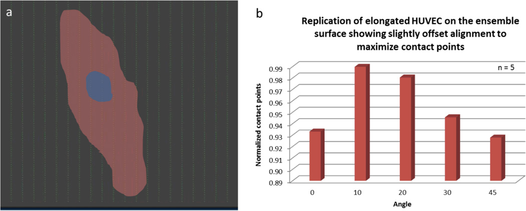
Our results indicate that HUVECs were largely aligned and elongated parallel to the y-axis, with slight offset of 10° to 30°. This retention and alignment may suggest that endothelial cells are responding to the wall shear stress but are also being affected by the nanoparticle array. Since the wall shear stress of 1.5 dyne/cm2 is insufficient to align endothelial cells,[44] this orientation may be considered as a combined effect of both the flow and the nanoparticle array. Their slight offset may serve to maximize the contact points or attachment sites on the pro-adhesive surface. More particularly, when we overlaid the elongated cells to the nanoparticle array, we noticed stretched or elongated cells maximize their contact points by orienting more toward 10° to 20° while round or non-elongated cells show no preference in orientation (Figure 7). Whether this spatial specificity is a feature of a cell’s response to wall shear stress or a general aspect of the orientation of endothelial cells remains unknown.
Figure 7.
The effect of nanoparticle array on the orientation of HUVECs. A) An outline of an elongated cell overlaid the nanoparticle array up to scale. The cell is orienting at the angle to maximize the attachment sites or nanoparticles. B) A bar graph illustrating the most favorable orientation of an elongated cell. N is the number of elongated cells annotated.
4. Conclusion
Creating cell substrate surfaces covered with ensembles of nanowells containing entrapped charged, ligand-bearing nanoparticles, created by size dependent self-assembly and electron beam lithography, we were able to transform minimally cell adherent PMMA surfaces into pro-adhesive surfaces. Endothelial cells grown on these surfaces demonstrated greater adhesion and resistance to detachment, in comparison to simple surfaces, when subjected to wall shear stress from overriding fluid flow. Endothelial cell orientation was also altered by these engineered surfaces with cells being elongated and oriented more toward the direction of the flow but slightly offset to accommodate more attachment sites, thus further enhancing flow resistant cell adhesion. Adaptation of this method to enhance the endothelialization of cardiovascular implant devices such as stents, stent-grafts and mechanical circulatory assist devices, may be a valuable application of this approach leading to enhanced implant safety and effectiveness. EBL was utilized in our studies as an effective high-resolution surface nanotexturing method to demonstrate proof-of-principle of this approach. If formation of nano-ensembles finds practical application, i.e. for a large-surface cardiovascular implant, then modification of the EBL approach and scale-up will be required to adapt this nanotexturing method to clinical trials and commercialization. Alternatively, it is conceivable that a differing method may be utilized for baseline surface nanotexturing, such as replica molding from EBL nanopatterns, for ensemble formation. Use of different materials may become necessary to meet the mechanical and physiological requirements of such cardiovascular implant devices. For example, hydrophilic and more biocompatible polyethylene glycol (PEG) may replace relatively hydrophobic and less biocompatible PMMA. Silicon substrate may be replaced with stainless steel, a common material for stents. Replica molding technique may be required to transfer nanometer patterns to a non-flat surface as exists with stents.
5. Experimental Section
5.1. Development of Nanoparticle Array
The fabrication of the nanoparticle array involves multiple stages. First, a diced (1 cm2) p-doped silicon wafer chip (boron-doped, 450–648-µm thick and 4–75 Ω/cm, Exsil, Inc., Prescott, AZ, USA) was spin-coated with a photoresist, which is composed of a mixture of 2:3 950 PMMA (polymethyl methacrylate) / C4 thinner (Microchem, Newton, MA, USA); resulting in about 80 nm thickness (measured by a KLA-Tencor alpha-step 200 profilometer, Milpitas, CA, USA and Veeco Dimension 3100 atomic force microscope, Bruker AXS, Santa Barbara, CA, USA). The coated chip was then hot-baked to remove any excess residues and to facilitate resist adhesion and subsequently subjected to electron beam lithography, which involves nanometer pattern generation system (NPGS; JC Nabity, Bozeman, MT, USA) and FEI Inspec scanning electron microscope (SEM; Hillsboro, OR, USA) to etch wells of different sizes (mostly 100 nm, but 300, 500, and 900 nm were also used) and separated at different x-y spacings (mostly 5×1 µm2 but 1×1, 5×5, 5×10, and 5×20 µm2 were also used). The etched array was developed with 1:3 methyl isobutyl ketone (MIBK; Microchem Corp., Newton, MA, USA) / isopropyl alcohol (IPA; Honeywell, Morristown NJ, USA) developer for 60 s, followed by 30 s with IPA, then rinsed with deionized water and dried with nitrogen gas. The sizes of wells were measured by the Veeco Dimension 3100 AFM.
Carboxylated, fluorescent polystyrene nanoparticles were covalently conjugated with GRGDSPK peptide (Anaspec, Inc. Fremont, CA, USA) by employing N-(3-dimethylaminopropyl)-N-ethylcarbodiimide hydrochloride (Sigma-Aldrich, St. Louis, MO, USA) as a carboxyl activating agent. The full protocol of covalent antibody conjugation can be found from Bangs Laboratories or Molecular Probes; and from Rosenman et al.[16] 1 µl droplet that contained RGD-conjugated nanoparticles was placed over the developed patterns and subsequently immobilized into the wells using a vibrational droplet manipulation technique.[19] Rapid vibration of droplets provided sufficient energy for nanoparticles to better assemble into nanowells with substantially higher saturation. The metal wire was connected to a microcontroller (Arduino Duemilanove, SparkFun Electronics, Boulder, CO, USA) interfaced with a USB port that can be programmed to control the three-axis manipulations of the droplet. A Nintendo game pad was attached to the microcontroller so that x-, y- and z-movements of a metal wire (thus the droplet) could be made possible from the experimenter’s input. The movie of the event can be seen in Supporting Information 1.[19]
5.2. Biochamber Design
Biochambers were constructed out of acrylic resin. A channel of 1×1×5 cm3 was carved with a drill bit to fit up to 5 chips (Supporting Information 2). The aluminum case holding the biochamber was also made using a vertical milling machine with digital readouts (Model: scv-2f, Republic Lagun Machine Tool Co., Harbor City, CA USA). Fittings and tubes (Value Plastics Inc., Fort Collins, CO, USA) were connected to a media reservoir where the pulsatile (peristaltic) pump (Cole-Palmer, Vernon Hills, IL, USA) pumps the media through the biochamber and back into the media reservoir. The reservoir also has an extra hole for circumvent air like oxygen and carbon dioxide necessary for cells. All tubings, connectors, adapters, and biochamber were soaked in 10% bleach for 10 min, rinsed with ultrapure water followed by 70% ethanol, and dried in laminar flow hood before use. The movie of the biochamber operation can be seen in Supporting Information 3.
5.3. Cell Culture Methods – Static and Flow Conditions
HUVECs were grown in complete M199 media, which contains 15% (v/v) fetal calf serum, 1% (v/v) of 0.2 M glutamine, 1.5% (v/v) of 1 M HEPES, 1% (v/v) of penicillin/streptomycin, 1.8% (v/v) of sodium bicarbonate, 25 mg of endothelial cell growth supplement (ECGS), 26.4 mg of sodium salt, and M199 medium to make a total 500 ml. Cells at 80% confluent or more were detached by trypsin and collected by centrifugation. Resuspended cells were seeded onto sterilized chips for 24 hours before subjecting to flow test. The flow rate was determined by collecting the amount of media pumped per minute. The wall shear stress was calculated using the standard equation τw = 4 μQ / πab (from the basis of Poiseuille’s law and Reneman et al.[44] where μ is the blood viscosity, Q is the flow rate, a is the cross sectional area, and b is the height of the channel. For static condition, cells were cultured for 4, 36 and 72 hours before staining. Cell culture media were changed every 2 days.
5.4. Immunocytochemistry Staining of Endothelial Cells
HUVECs were stained using actin cytoskeleton/focal adhesion staining kit (Millipore, MA, USA). Basically, cells were fixed with 4% para-formaldehyde for 15 min, then washed and permeated the membrane with 0.05% Triton X for 5 min. Cells were then washed and blocked with protein standard (bovine serum albumin; BSA) and subsequently stained with anti-vinculin for 1 hour. Cells were then washed and subsequently stained with fluorescein isothiocyanate conjugated mouse anti-immunoglobulin G (mIgG-FITC) to label vinculin and tetramethyl rhodamine isothicyanate (TRITC) conjugated Phalloidin to selectively label F-actin. After washing off all the excess stains, cells were then mounted in vector shield with DAPI.
5.5. Image Analysis
The Veeco Dimension 3100 AFM was used to check the etched patterns. It was operated in tapping mode with integral gain of about 0.2 and amplitude of about 1.2 V. The inverted epifluorescence microscope (Nikon) was also used to image the stained HUVECs. For cell counting, we used ImageJ (National Institutes of Health, USA) where the pixels of 50 or higher were counted in binary image mode.
5.6. Statistics
All Statistical analysis was performed using Microsoft Excel 2010. TTEST was analyzed using one-tailed distribution and two-sample unequal variance type.
Supplementary Material
Acknowledgements
The authors thank Dr. Brooke Beam and Paul Lee of the Keck’s facility at the University of Arizona for their assistance in AFM, SEM, and confocal imaging. We also thank Dr. Felipe T. Lee-Montiel and Dr. David J. You for biochamber design. This work was supported by BIO5 Institute, as well as fellowship support for Phat L. Tran (NIH Cardiovascular Training Grant HL007955).
Footnotes
Supporting Information
Supporting Information 1: The movie for vibrational droplet manipulation to saturate the nanoparticles into the nanowells.
Supporting Information 2: Biochamber design.
Supporting Information 3: The movie for biochamber operation.
Supporting Information is available online from the Wiley Online Library or from the author.
Contributor Information
Phat L. Tran, Biomedical Engineering Graduate Interdisciplinary Program and Department of Biomedical Engineering, The University of Arizona, Tucson, Arizona 85721, USA
Jessica R. Gamboa, Biomedical Engineering Graduate Interdisciplinary Program and Department of Biomedical Engineering, The University of Arizona, Tucson, Arizona 85721, USA
Katherine E. McCracken, Department of Agricultural and Biosystems Engineering, The University of Arizona, Tucson, Arizona 85721, USA
Mark R. Riley, Department of Agricultural and Biosystems Engineering, The University of Arizona, Tucson, Arizona 85721, USA
Marvin J. Slepian, Biomedical Engineering Graduate Interdisciplinary Program and Department of Biomedical Engineering, The University of Arizona, Tucson, Arizona 85721, USA Sarver Heart Center and Department of Medicine, College of Medicine, The University of Arizona, Tucson, Arizona 85721, USA.
Jeong-Yeol Yoon, Biomedical Engineering Graduate Interdisciplinary Program and Department of Biomedical Engineering, The University of Arizona, Tucson, Arizona 85721, USA; Department of Agricultural and Biosystems Engineering, The University of Arizona, Tucson, Arizona 85721, USA.
References
- 1.Khademhosseini A, Langer R, Borenstein J, Vacanti JP. Proc. Natl. Acad. Sci. USA. 2006;103:2480–2487. doi: 10.1073/pnas.0507681102. [DOI] [PMC free article] [PubMed] [Google Scholar]
- 2.Moon JJ, Hahn MS, Kim I, Nsiah BA, West JL. Tissue Eng. A. 2009;15:579–585. doi: 10.1089/ten.tea.2008.0196. [DOI] [PMC free article] [PubMed] [Google Scholar]
- 3.Feinberg AW, Schumacher JF, Brennan AB. Acta Biomater. 2009;5:2013–2024. doi: 10.1016/j.actbio.2009.01.032. [DOI] [PubMed] [Google Scholar]
- 4.Zorlutuna P, Rong Z, Vadgama P, Hasirci V. Acta Biomater. 2009;5:2451–2459. doi: 10.1016/j.actbio.2009.03.027. [DOI] [PubMed] [Google Scholar]
- 5.Kim DH, Lipke EA, Kim P, Cheong R, Thompson S, Delannoy M, Suh KY, Tung L, Levchenko A. Proc. Natl. Acad. Sci. USA. 2010;107:565–570. doi: 10.1073/pnas.0906504107. [DOI] [PMC free article] [PubMed] [Google Scholar]
- 6.Dalby MJ, Gadegaard N, Tare R, Andar A, Riehle MO, Herzyk P, Wilkinson CDW, Oreffo ROC. Nature Mater. 2007;6:997–1003. doi: 10.1038/nmat2013. [DOI] [PubMed] [Google Scholar]
- 7.Kanchanawong P, Shtengel G, Pasapera AM, Ramko EB, Davidson MW, Hess HF, Waterman CM. Nature. 2010;468:580–584. doi: 10.1038/nature09621. [DOI] [PMC free article] [PubMed] [Google Scholar]
- 8.Lu J, Rao MP, MacDonald NC, Khang D, Webster TJ. Acta Biomater. 2008;4:192–201. doi: 10.1016/j.actbio.2007.07.008. [DOI] [PubMed] [Google Scholar]
- 9.Nel AE, Mädler L, Velegol D, Xia T, Hoek EMV, Somasundaran P, Klaessig F, Castranova V, Thompson M. Nature Mater. 2009;8:543–557. doi: 10.1038/nmat2442. [DOI] [PubMed] [Google Scholar]
- 10.Li J, Ding M, Fu Q, Tan H, Xie X, Zhong Y. J. Mater. Sci. Mater. Med. 2008;19:2595–2603. doi: 10.1007/s10856-007-3354-5. [DOI] [PubMed] [Google Scholar]
- 11.Nie Z, Kymacheva E. Nature Mater. 2008;7:277–290. doi: 10.1038/nmat2109. [DOI] [PubMed] [Google Scholar]
- 12.Kim P, Kim DH, Kim B, Choi SK, Lee SH, Khademhosseini A, Langer R, Suh KY. Nanotechnology. 2005;16:2420–2426. doi: 10.1088/0957-4484/16/10/072. [DOI] [PubMed] [Google Scholar]
- 13.Meyers SR, Khoo X, Huang X, Walsh EB, Grinstaff MW, Kenan DJ. Biomaterials. 2009;30:277–286. doi: 10.1016/j.biomaterials.2008.08.042. [DOI] [PMC free article] [PubMed] [Google Scholar]
- 14.Hoover DK, Chan EWL, Yousaf MN. J. Am. Chem. Soc. 2008;130:3280–3281. doi: 10.1021/ja711016m. [DOI] [PubMed] [Google Scholar]
- 15.Junkin M, Wong PK. Biomaterials. 2011;32:1848–1855. doi: 10.1016/j.biomaterials.2010.11.009. [DOI] [PMC free article] [PubMed] [Google Scholar]
- 16.Rosenman J, Kempczinski R, Pearce W, Silberstain E. J. Vasc. Surg. 1985;2:778–184. [PubMed] [Google Scholar]
- 17.Carr H, Vohra R, Sharma HSJ, Rooney O, Dodd PDF, Walker M. Ann. Vasc. Surg. 1996;10:469–475. doi: 10.1007/BF02000595. [DOI] [PubMed] [Google Scholar]
- 18.Pislaru SV, Harbuzariu A, Agarwal G, Witt T, Gulati R, Sandhu NP, Mueske C, Kalra M, Simari RD, Sandhu GS. Circulation. 2006;114:I314–I318. doi: 10.1161/CIRCULATIONAHA.105.001446. [DOI] [PubMed] [Google Scholar]
- 19.Tran PL, Gamboa JR, You DJ, Yoon J-Y. Anal. Bioanal. Chem. 2010;398:759–768. doi: 10.1007/s00216-010-3990-3. [DOI] [PMC free article] [PubMed] [Google Scholar]
- 20.Lehnert D, Wehrle-Haller B, David C, Weiland U, Ballestrem C, Imhof BA, Bastmeyer M. J. Cell Sci. 2004;117:41–52. doi: 10.1242/jcs.00836. [DOI] [PubMed] [Google Scholar]
- 21.Girard PP, Cavalcanti-Adam EA, Kemkemer R, Spatz JP. Soft Matter. 2007;3:307–326. doi: 10.1039/b614008d. [DOI] [PubMed] [Google Scholar]
- 22.Flemming RG, Murphy CJ, Abrams GA, Goodman SL, Nealey PF. Biomaterials. 1999;20:573–588. doi: 10.1016/s0142-9612(98)00209-9. [DOI] [PubMed] [Google Scholar]
- 23.Nicosia R, Bonano E. Am. J. Path. 1991;38:829–833. [PMC free article] [PubMed] [Google Scholar]
- 24.Perlin L, MacNeil S, Rimmer S. Soft Matter. 2008;4:2331–2349. [Google Scholar]
- 25.McMurray RJ, Gadegaard N, Tsimbouri PM, Burgess KV, McNamara LE, Tare R, Murawski K, Kingham E, Oreffo ROC, Dalby MJ. Nature Materials. 2011;10:637–644. doi: 10.1038/nmat3058. [DOI] [PubMed] [Google Scholar]
- 26.Seyfert S, Voigt A, Kabbeckkupijai D. Biomaterials. 1995;16:201–207. doi: 10.1016/0142-9612(95)92118-p. [DOI] [PubMed] [Google Scholar]
- 27.van Wachem PB, Hogt AH, Beugeling T, Feijen J, Bantjes A, Detmers JP, van Aken WG. Biomaterials. 1987;8:323–328. doi: 10.1016/0142-9612(87)90001-9. [DOI] [PubMed] [Google Scholar]
- 28.Lee JH, Jung HW, Kang IK, Lee HB. Biomaterials. 1994;9:705–711. doi: 10.1016/0142-9612(94)90169-4. 15. [DOI] [PubMed] [Google Scholar]
- 29.Ohgaki M, Kizuki T, Katsura M, Yamashita K. J. Biomed Mater Res. 2001;57:366–373. doi: 10.1002/1097-4636(20011205)57:3<366::aid-jbm1179>3.0.co;2-x. [DOI] [PubMed] [Google Scholar]
- 30.Chen SL, Zhou J, Jiang S. Langmuir. 2003;19:2859–2864. [Google Scholar]
- 31.Chin V, Collins BE, Sailor MJ, Bhatia SN. Adv Mater. 2001;13:1877–1880. [Google Scholar]
- 32.Carpenter J, Khang D, Webster TJ. Nanotechnology. 2008;19:505103. doi: 10.1088/0957-4484/19/50/505103. [DOI] [PubMed] [Google Scholar]
- 33.Dalby MJ, Riehle MO, Johnstone H, Affrossman S, Curtis ASG. Biomaterials. 2002;23:2945–2954. doi: 10.1016/s0142-9612(01)00424-0. [DOI] [PubMed] [Google Scholar]
- 34.Rouslahti E. Annu Rev Cell Dev Biol. 1996;12:697–715. doi: 10.1146/annurev.cellbio.12.1.697. [DOI] [PubMed] [Google Scholar]
- 35.Mooney DJ, Langer R, Hansen LK, Vacanti JP, Ingber DE. Mater. Res. Soc. Proc. 1992;252:199–204. [Google Scholar]
- 36.Holland J, Hersh L, Bryhan M, Onyiriuka E, Ziegler L. Biomaterials. 1996;22:147–156. doi: 10.1016/0142-9612(96)00028-2. [DOI] [PubMed] [Google Scholar]
- 37.Ott MJ, Ballermann BJ. Surgery. 1995;117:334–339. doi: 10.1016/s0039-6060(05)80210-7. [DOI] [PubMed] [Google Scholar]
- 38.Davies PF. Physiol. Rev. 1995;75:519–560. doi: 10.1152/physrev.1995.75.3.519. [DOI] [PMC free article] [PubMed] [Google Scholar]
- 39.Davies PF, Barbee KA, Volin MV, Robotewskyj A, Chen J, Joseph L, Griem ML, Wernick MN, Jacobs E, Polacek DC, et al. Annu. Rev. Physiol. 1997;59:527–549. doi: 10.1146/annurev.physiol.59.1.527. [DOI] [PubMed] [Google Scholar]
- 40.Kader KN, Yoder CM. Mater Sci Eng C. 2008;28:387–391. [Google Scholar]
- 41.Malek AM, Izumo S. J. Cell Sci. 1996;109:713–726. doi: 10.1242/jcs.109.4.713. [DOI] [PubMed] [Google Scholar]
- 42.Nerem RM, Alexander RM, Chappell DC, Medford RM, Varner SE, Taylor WR. Am. J. Med. Sci. 1998;316:169–175. doi: 10.1097/00000441-199809000-00004. [DOI] [PubMed] [Google Scholar]
- 43.Tajima S, Chu JSF, Li S, Komvopoulos K. J. Biomed. Mater. Res. A. 2008;84:828–836. doi: 10.1002/jbm.a.31539. [DOI] [PubMed] [Google Scholar]
- 44.Reneman RS, Arts T, Hoeks APG. J. Vasc. Res. 2006;43:251–269. doi: 10.1159/000091648. [DOI] [PubMed] [Google Scholar]
Associated Data
This section collects any data citations, data availability statements, or supplementary materials included in this article.


