Abstract
Porcelain fused to zirconia (PFZ) restorations are widely used in prosthetic dentistry. However, their susceptibility to fracture remains a practical problem. The failure of PFZ prostheses often involves crack initiation and growth in the porcelain, which may be followed by fracture along the porcelain/zirconia (P/Z) interface. In this work, we characterized the process of fracture in two PFZ systems, as well as a newly developed graded glass-zirconia structure with emphases placed on resistance to interfacial cracking. Thin porcelain layers were fused onto Y-TZP plates with or without the presence of a glass binder. The specimens were loaded in a four-point-bend fixture with the thin porcelain veneer in tension, simulating the lower portion of the connectors and marginal areas of a fixed dental prosthesis (FDP) during occlusal loading. The evolution of damage was observed by a video camera. The fracture was characterized by unstable growth of cracks perpendicular to the P/Z interface (channel cracks) in the porcelain layer, which was followed by stable cracking along the P/Z interface. The interfacial fracture energy GC was determined by a FEA taking into account stress shielding effects due to the presence of adjacent channel cracks. The resulting GC was well less than commonly reported values for similar systems. Fracture in the graded Y-TZP samples occurred by a single channel crack at a much greater stress than for PFZ. No delamination between the residual glass layer and graded zirconia occurred in any of the tests. Combined with its enhanced resistance to edge chipping and good esthetic quality, graded Y-TZP emerges as a viable material concept for dental restorations.
Keywords: interfacial fracture energy, delamination, all-ceramic dental restorations, porcelain-veneered zirconia, graded zirconia
1. Introduction
Posterior dental prostheses are commonly made of porcelain veneer fused to metal (PFM) or zirconia (PFZ) framework. Porcelain has good esthetic qualities, but is susceptible to premature fracture. Although the reported incidence of porcelain fracture is higher in PFZ relative to PFM [1–6], the two systems share similar damage forms. Fracture may occur from edge chipping (“cohesive” failure) [1, 6–9] or interfacial fracture (“delamination”) [10–12]. The higher porcelain chipping and delamination rates observed in PFZ are due to the development of deleterious tensile residual stresses [13–17] and the low interfacial fracture energy GC of PFZ relative to PFM [18, 19]. The residual thermal stress occurs during heat treatment due to the mismatch in thermal expansion coefficient between veneer and core as well as the low thermal diffusivities characterizing most ceramics. It is pointed out that any crown or FPD failure other than edge chipping must involve a crack reaching the interface between veneer and core. Indeed, this has been demonstrated in several in vitro studies on fatigue of PFZ restorations [20–23]. Hence, assessing and improving interfacial strength is an important aspect of material design.
There have been several approaches for preventing the delamination problem of PFZs. One such approach is to use a glass bonding layer to improve the adhesion of porcelain to zirconia. Unfortunately, this can only marginally, if at all, increase the resistance to delamination. This is because when cracks in the porcelain veneer reach the veneer/core interface, they tend to graze along the weak interface or deflect into the porcelain veneer rather than penetrate the stiffer and tougher zirconia core. A much more effective strategy is to alter the crack growth route so that it penetrates into the zirconia framework via proper engineering of the interfacial microstructure [24, 25]. This way, the superior strength and toughness of zirconia could effectively hold off the crack, adverting porcelain delamination altogether. Using a glass-ceramic infiltration technique, a functionally graded glass-zirconia material has been developed [25]. Previously, we have examined the fracture resistance of this material, including subsurface flexural fracture [26–28] and edge chipping resistance [29, 30]. The results showed that this material retains the proven strength benefit of Y-TZP, yet it has a superior esthetic quality [24]. Here, we examine the fracture resistance of its interface.
Considerable work has been devoted to assessing the interfacial adhesive strength of porcelain-veneered zirconia restorations. This is generally done by subjecting the material to some form of external forces and examining the ensuing fracture pattern [31–34]. While useful for routine screening, this approach yields no direct information on the interfacial fracture energy GC. A simple means for evaluating GC for dental restorations is the four-point-bend bilayer configuration. Several studies have used this method to determine the interfacial energy of PFM with various metal copings [19, 35] or different porcelain-veneered zirconia systems [18]. However, the fracture process in such tests can be complex; even simple configurations such as thin-film bilayers under tension are known to fail in an intricate process involving multiple channel cracks in the hard film and delamination between film and substrate (e.g., [36, 37]). In addition, the multiple channel cracks may greatly alter the fracture resistance as well as the calculations of interfacial fracture energy [38, 39].
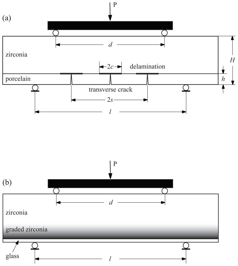
In this study, we elucidate the fracture process and fracture resistance of some PFZ systems as well as a newly-developed graded Y-TZP coated by a glass layer (hereafter, we designate this material as graded Y-TZP) due to tensile loading. Special emphasis is placed on resistance to interfacial fracture. Porcelain/zirconia bilayers and graded Y-TZP samples are loaded in the four-point-bend fixture shown in Fig. 1. Two PFZ systems are considered: porcelain fused directly onto zirconia and porcelain fused to zirconia in the presence of a glass binder. The latter is motivated by works showing that binders may greatly enhance interfacial fracture resistance [35]. The fracture process is observed from the specimen edge using a video camera equipped with a telescopic lens. The tests are supplemented by a 2D FEA for calculating interfacial fracture energy, taking into account the evolving fracture morphology. Section 2 describes the materials and methods used while Section 3 presents the test results. The latter is discussed in Section 4 in relation to dental restorations.
Fig. 1.
The porcelain/Y-TZP bilayer specimen (a) and graded Y-TZP specimen (b) used, shown in the four-point-bend fixture. Illustration (a) contains channel and delamination cracks used in the FEM model.
2. Materials and methods
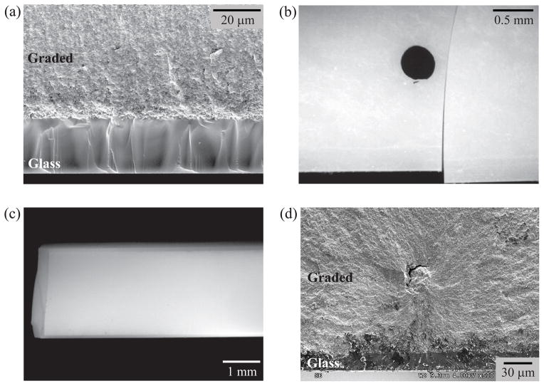
The materials used were porcelain fused to zirconia (PFZ) and graded Y-TZP. For PFZ, two configurations were studied: porcelain fused directly onto zirconia (P group) and porcelain fused to zirconia in the presence of a thin glass binder (Y group). Prior to veneering, the zirconia (Tosoh Y-TZP, CTE = 10.5 x 10⁻⁶ K−1) surface was sandblasted with 50 μm Al2O3 particles for 5 s at a standoff distance of 10 mm and a compressed air pressure of 2 bars. The P group was produced by laying porcelain powder (Heraceram Zirconia, leucite-reinforced porcelain, CTE = 10.5 x 10⁻⁶ K−1, Heraeus Kulzer GmbH, Hanau, Germany) onto zirconia and heating to 870 °C with a dwell time of 1 min. For the Y group, an adhesive paste having a thickness of approximately 0.1 mm (Heraceram ZR-Adhesive paste, Heraeus Kulzer GmbH, CTE = 10.5 x 10⁻⁶ K−1) was first applied to the zirconia veneering surface and fired at 1050 °C for 20 min to help wet the zirconia surface. Upon cooling to room temperature, the same porcelain used for the P group was applied and fired. Examination of the interface region in the Y specimens with a high-resolution optical microscope revealed no visible sign of interlaminar glass adhesive, indicating good interdiffusion between glass and porcelain. Hence, both P and Y groups could be characterized by a single veneer layer. The graded Y-TZP was prepared as described earlier [25, 40]. Briefly, an in-house prepared glass with composition similar to dental porcelain in the form of powder slurry was first applied on pre-sintered Y-TZP (1350 °C for 1 hour). Glass infiltration and densification occurred in a single process at 1450 °C for 2 hours, resulting in a structure consisting of a 15 to 40 μm thick residual glass layer followed by a 120 μm thick graded layer and finally a bulk Y-TZP. Fig. 2a shows a micrograph of a graded Y-TZP sample broken by bending. One observes a uniform residual glass layer without large voids or flaws. The glass layer is attached to the Y-TZP core through a graded glass-zirconia layer where the content of intergranular glass is gradually diminishing.
Fig. 2.
Micrographs for graded Y-TZP loaded in the four-point-bend fixture: (a) SEM image of a fractured bar showing a thin (25 μm) residual glass layer on a graded Y-TZP and no delamination crack, (b) A video frame taken right after fracture showing a single channel crack, (c) Post-mortem optical image of the sample in (b) taken normal to the surface of the glass layer showing no multiple channel cracks, and (d) Fracture surface in graded zirconia, revealing that fracture initiates from the graded Y-TZP layer below the interface with the glass layer. The dark spot in (b) indicates the location of Vickers indentation.
All specimens were fabricated in the desired form: length L = 30 mm, total thickness H = 2.7 mm and specimen width b = 2.5 mm, see Fig. 1. At least 7 specimens were prepared for each group. The porcelain thickness h for both PFZ groups is 0.4 mm. The fracture tests were conducted using the four-point-bend test [41]. Fig. 1 shows the PFZ (a) and graded Y-TZP (b) specimens in their loading fixture. The distances between lower and upper supporting pins, l and d, were 20 and 10 mm, respectively. Prior to testing, the tensile surfaces of the PFZ samples were polished down to a 1 μm diamond suspension finish and then indented at their center points by a Vickers indenter at a load of 5 N to introduce an artificial flaw for crack initiation (crack length of ~ 45 μm). In the case of graded Y-TZP, some specimens (n = 10) were tested as fabricated, while in others (n = 7), the tensile surface was indented with a Vickers tool at 10 N load (crack length of ~ 70 μm). The specimens were loaded in a standard universal testing machine at a rate of 0.1 mm/min. One specimen side face, polished to mirror surface quality, was observed by a video camera (Canon EOS-7D) equipped with a high-power zoom lens (Optem, Inc.).
Referring to Fig. 1, the load P produces bending moment M = P(l − d)/4 in the beam portion bounded by the upper pins. The tensile stress at the lower surface of the PFZ bilayer, σp, where fracture initiates, is easily found from beam theory as [38]
| (1a) |
where E and ν denote Young’s modulus and Poisson’s ratio, and subscript 1 and 2 indicate porcelain and Y-TZP (Fig. 1a). For the graded material, the tensile stress at the lower surface of the residual glass layer, σg, and at the adjacent Y-TZP surface, σy, are found from Eq. 1a. Noting that the thicknesses of the graded zirconia layer and glass layer are very small compared to the total specimen thickness, and that the modulus of the glass layer is small compared to that of zirconia. Hence, the prevalent condition (6h/H)/(E2/E1) ≪ 1 yields:
| (1b) |
| (1c) |
The following elastic properties were used in these calculations: (E1, E2, Eg) = (70, 210, 70) GPa, (ν1, ν2, νg) = (0.20, 0.32, 0.22), where “g” stands for glass. The energy release rate (ERR) for interfacial cracking in the PFZ samples was determined by a 2D FEA. The calculations were performed with the aid of a commercial FEM code (Abaqus, Inc.) as described earlier [38].
3. Results
3.1 Porcelain/Y-TZP
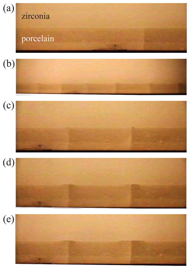
Fig. 3 shows select frames from a video sequence for a porcelain/zirconia bilayer (P group). A channel crack popped in from the lower surface at stress σp = 93.1 MPa, arresting at the interface (a). Interestingly, this crack did not initiate from the Vickers indent (located in the specimen’s plane of symmetry passing through the dark spot). At slightly greater loads, channel cracks, spaced about 3 times layer thickness apart, popped in (b). Cracking along the P/Z interface initiated nearly spontaneously from every tip of the channel cracks starting at stress σp = 128.4 MPa (c). With increasing load, the interface cracks grew stably in a rather symmetric fashion [(d) and (e)].
Fig. 3.
Select frames from a video sequence for porcelain/Y-TZP (P group): (a) Onset of first channel crack (σp = 93.1 MPa), (b) A lower magnification at a slightly larger load showing nearly evenly spaced channel cracks (σp = 102 MPa), (c) Onset of delamination from the tips of the channel cracks (σp = 124.8 MPa), (d) and (e) Images taken during the (stable) delamination growth (σp = 163.2 MPa and 184.8 MPa, respectively). σp denotes the tensile stress at the lower surface of the porcelain layer as evaluated from Eq. 1(a). The thickness of the porcelain layer 0.4 mm.
Fig. 4 is a magnified view of a typical crack path in the Y group. The channel crack had split into two horizontal cracks that grew along a rather wavy interface [18]. No glass adhesive at the interface was evident, indicating good interdiffusion between glass and porcelain. The tensile stress needed to initiate a channel crack in the porcelain layer was calculated from Eq. 1a using corresponding loads recorded during the experiments. The combined data yielded mean and SD values of 90.3 and 15.2 MPa, respectively.
Fig. 4.
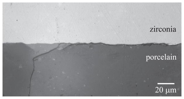
Optical microscope image of porcelain/glass/Y-TZP (Y group) specimen after unloading. The channel crack in the porcelain branches out into two delamination cracks. No glass adhesive layer is visible at the interface.
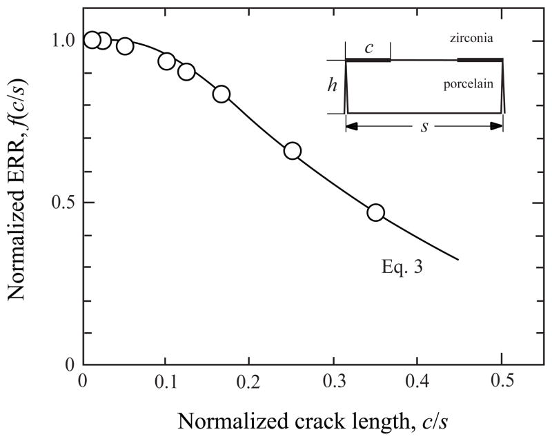
The fracture morphology was modelled as shown in Fig. 1a. The specimen consisted of an array of channel cracks, spaced in intervals of distance s, which extended across the full veneer thickness and width. Interface cracks of length c extended from the tip of each channel crack in both directions. Because of the relative smallness of the veneer layer, only a cell element as shown in the inset in Fig. 5 was modelled. Additionally, taking advantage of symmetry, the loading was represented by a uniform bending strain applied along the midsection. The energy release rate G = G(c/s) for a given crack length c is found from
Fig. 5.
Normalized energy release rate f vs. normalized delamination length c/s for the four-point-bend porcelain/Y-TZP specimen (Fig. 1a). Symbols are from the FEM analysis. Solid line is an empirical fit to the FEM data (Eq. 3).
| (2a) |
| (2b) |
where Gss is the interfacial ERR for the limit case c/s ≪ 1 or a single channel crack [41], while f(c/s) is a certain function of c/s which we add here in order to account for the presence of adjacent channel cracks. This function depends on Dundur’s parameters α and β [37, 39].
Fig. 5 (symbols) shows the variation of f(c/s) or normalized ERR with normalized delamination length for the present porcelain/YTZ-P system (α = −0.47, β = 0.35) as obtained from our FEA. (The calculations are similar to those described in [38] and hence not repeated here.) The ERR rapidly diminishes with normalized crack length, which highlights the need to account for stress shielding from multiple channel cracks in the fracture analysis. The behavior near c/s = 0.5 (complete delamination) varied greatly. To help in routine calculations, the FEM data are empirically fitted by a function f (solid line in Fig. 5):
| (3) |
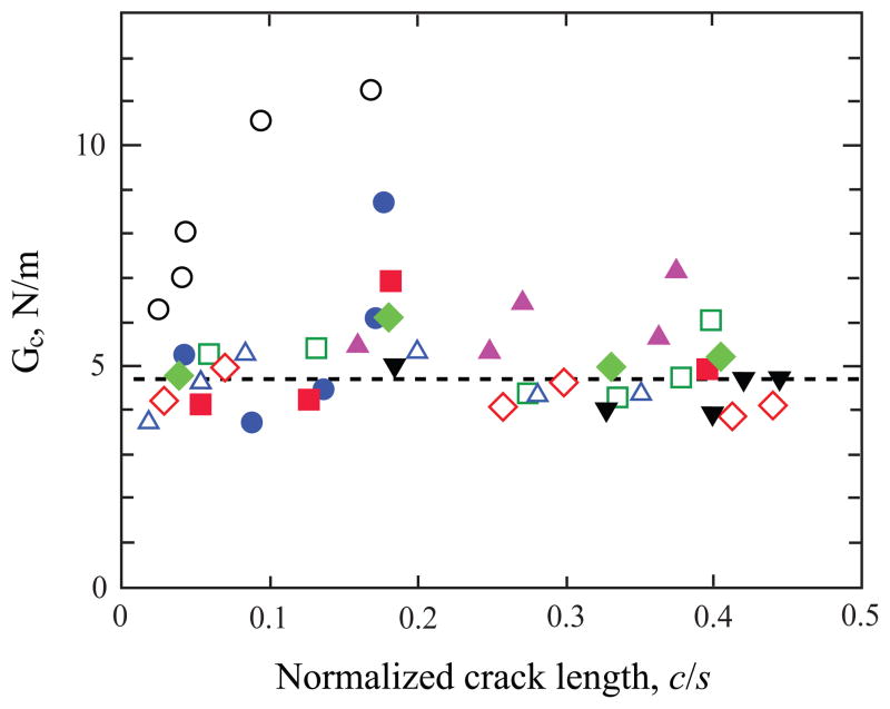
Using this in Eq. 2 together with concurrent test data for P, c and s and the (fixed) geometric and materials variables, the variation of critical energy release rate GC with normalized crack length c/s can be found. The results are shown in Fig. 6, where different symbols represent different test specimens. The values of GC for the Y (filled circles) and P (unfilled circles) groups seems indistinguishable, in line with the good diffusion of the glass adhesive into porcelain as evident from Fig. 4. Notwithstanding the large scatter, GC seems independent of crack length, which would confirm it as a material property. It should be noted that this quantity is a mixed-mode type with nearly equal parts of mode I and mode II ERR components [42]. The average and standard deviation values of GC are 4.8 N/m and 1.4 N/m, respectively. This is well below the pure mode I value for porcelain of 11.0 N/m (e.g., [26]), indicating a very small mode II fracture energy.
Fig. 6.
Variation of interfacial energy release rate with normalized delamination length c/s for all porcelain-veneered zirconia samples tested. The fracture energy is obtained from Eqs. 2 and 3; the mean value is represented by a dashed line. Open and filled symbols correspond to porcelain fused onto zirconia directly (P group) or in the presence of a thin glass binder (Y group), respectively. Different symbols are used to represent different samples.
3.2 Graded Y-TZP
As exemplified in Fig. 2b, the graded Y-TZP fractured by a single channel crack. This is confirmed in Fig. 2c, which shows no other cracks on the surface of the residual glass. It is also apparent from Fig. 2a that no delamination occurred along the glass/graded Y-TZP interface. For this reason the ERR was not calculated for this material. As is apparent from Fig. 2d, the crack has initiated in the graded Y-TZP, somewhat below the interface with the glass layer, consistent with the lack of multiple cracks in the glass layer. From Eq. 1c, the corresponding mean (SD) tensile stress is found as 820 (120) MPa. The stress values for the samples which were pre-indented by a 10 N Vickers indentation were slightly smaller, i.e. 685 (102) MPa, consistent with the presence of an initial crack extending deeper into the graded Y-TZP. Using Eq. 1b, the mean (SD) tensile stress at the outer surface of the residual glass layer is found to be 261 (38) MPa. This level is believed to be insufficient to induce a crack in the glass layer; as shown in Chai et al. [43], the failure stress for a mirror-like glass surface is several times larger.
4. Discussion
The fracture process in a thin porcelain layer fused onto zirconia with or without an intermittent glass binder and in a graded Y-TZP was determined using the four-point-bend specimen. For the PFZ systems channel cracks initiated and grew in the porcelain layer nearly simultaneously. For this reason the stress at which this occurred must reflect failure stress, σF, a quantity controlled by material microstructure rather than external flaws. Further support for this is given by the fact that our data are fairly close to the 77 to 85 MPa figure reported by White et al. [44] in testing porcelain bars. The channel cracks grew unstably before arresting at the P/Z interface. Delamination along the veneering interface grew stably from the tips of these cracks, roughly in a symmetric fashion. Our FEA showed that shielding afforded by adjacent channel cracks considerably enhanced the fracture resistance while at the same time altered the calculations of energy release rate. It is interesting to note that such mechanism for enhancing fracture resistance is also provided by enamel tufts in natural teeth [45], where the inner enamel layers are populated with filled fissures that appear to provide stress shielding, and in the fracture of canine teeth of wild animals, where multiple cracks in the enamel coat act to delay crack growth into the dentin substrate [46]. In the case of graded Y-TZP, no delamination occurred. Instead, the fracture was limited to a single surface normal crack that was initiated at a much greater stress than for PFZ. Adding this to its proven strength and fracture resistance characteristics [47], graded Y-TZP with the porcelain-like residual glass coating emerges as a viable concept for dental restoration.
It is interesting to examine interfacial fracture data obtained in similar works. Göstemeyer et al. [18] determined GC for four different porcelains veneered to a common Y-TZP. Both rapid and slow cooling rates were employed during specimen fabrication. The values for VM9, Triceram, Zirox and Lava for the rapid/slow cooling rates are 17.1/13.0, 13.3/9.8, 12.8/11.6, and 8.2/7.5 N/m, in that order. Le Thanh [48] studied porcelain veneered to zirconia and found GC-value of 12.4 N/m. The range of GC values in these two sources, which employed similar material combination as used here, well exceeds the present GC-value of 4.8 N/m. This departure may be partially attributed to the effect of stress shielding discussed above, which has not been considered in those studies. According to this work the onset of multiple channel cracks is governed by the veneer thickness to load span ratio, which was about 0.4 (e.g., Fig. 3b). It is possible that multiple channel cracks may have occurred in Refs. 20 and 44 (although this was not reported) given that the veneer thickness to load span ratio was less than 0.15. It should be noted that the stress decay controlling multiple cracking also depend on the veneer/core modulus mismatch; stiffer cores would reduce the distance between channel cracks [38, 39].
Our analysis involves several approximations that need be elaborated. (a) Eq. 1a is derived based on beam theory. With a span to beam thickness ratio about 4, our FEA shows that the error in calculating surface stress is less than 2% percent. The term E1/E2 in Eq. 1b represents a modulus correction over the monolith zirconia case E1/E2 = 1. Eq. 1b is a consequence of the minor effect on specimen curvature caused by the relative thinness of the glass and graded zirconia layers. For this reason the error in calculating σg from Eq. 1b and σy from Eq. 1b are also small, estimated to be less than 2%. (b) Our delamination analysis is based on a 2D model. This is justified since after the crack reaches the interface, it extends along the entire beam width before delamination can take place. Our FEM model is limited to a single cell element (see insert in Fig. 5). This is quite justified given the numerous vertical cracks present in the samples (e.g., about 10 cracks in the loading span of 10 mm, see Fig. 3b). (c) The scatter in Fig. 6 is believed to reflect material variations rather than measurement inaccuracies; the quantities c and s are determined from images such as shown in Fig. 3, with the error less than a few percent. The load P is obtained from a standard load cell, with typical error less than 1%. Since the stress at the lower specimen surface σp is proportional to load P, with error in σp on the order of 2%, the error in GC from Eq. 2 is estimated to be less than 5%.
It is interesting to comment on how the present study may relate to dental restorations. Interfacial cracks in this case may initiate after channel cracks forming at the occlusal surface reach the veneer/core interface. Although our study was concerned with PFZ systems, delamination may also occur in other systems, e.g., PFM. Syabsuwan and Swain [19] tested porcelain veneered to gold, palladium, nickel-chromium alloy or titanium copings. Prior to loading a channel crack was introduced over the entire porcelain layer. The fracture energy was calculated based on the load needed to cause a stable growth of the delamination, as deduced from changes in the system compliance. The reported GC-value ranged from 72.7 N/m for gold to 16.6 N/m for titanium coping. Tholey et al. [35] conducted a similar study for porcelain/titanium, in which the titanium interface was subjected to different surface treatments. The reported GC-values for titanium-Rocatec and titanium-sandblasted (10.8 and 12.6 N/m, respectively) are similar to the 16.6 N/m figure for porcelain/titanium reported in [19]. Such higher GC-values may increase the density of channel cracks. Once formed, the interface cracks may graze along the interface or deflect toward the free surface to form a chip; the specifics which are governed by the mode mix of the ERR and the interface toughness law. The former is controlled by such factors as local crown geometry and loading manner, as well as by residual stresses caused by mismatch in thermal expansion coefficients between veneer and core [13–17]. As for the toughness law, the fracture energy GC associated with a four-point-bend test is a mixed-mode type with nearly equal parts of mode I and mode II ERR. For general applications, the full mode mix toughness spectrum would be needed. Nevertheless, it may be assumed that material systems having small GC-values such as PFZ would favor interfacial fracture, while those with large GC-value such as PFM may fail by edge chipping. Multiple channel cracks may be expected only in those regions where the veneer layer can be considered thin, as in the connectors of FDP subject to intraoral loading.
5. Conclusions
When determining interfacial fracture energy using flexure of thin-film bilayers with the film being under tension, care must be taken to account for the formation of multiple channel cracks. Neglecting the stress shielding effect afforded by such cracks can lead to gross overestimates of interfacial fracture energy. Such a test configuration is most pertinent to the connector fracture or margin fracture of porcelain-veneered zirconia restorations, where the porcelain veneer is relatively thin. The present work shows that an effective way to circumvent the deleterious delamination problem in PFZ systems is to utilize a compositionally graded interlayer between the glass overlay and zirconia core.
Acknowledgments
This work was sponsored by funding from the United states National Institute of Health (P.I. Y. Zhang, Grant 2R01 DE017925), the United states National Science Foundation (P.I. Y. Zhang, Grant CMMI-0758530), and the Israeli Science Foundation (P.I. H. Chai, ISF Grant no. 810/09).
Footnotes
Disclosure
All authors declare no conflict of interest.
Publisher's Disclaimer: This is a PDF file of an unedited manuscript that has been accepted for publication. As a service to our customers we are providing this early version of the manuscript. The manuscript will undergo copyediting, typesetting, and review of the resulting proof before it is published in its final citable form. Please note that during the production process errors may be discovered which could affect the content, and all legal disclaimers that apply to the journal pertain.
References
- 1.Sailer I, Gottnerb J, Kanelb S, Hammerle CH. Randomized Controlled Clinical Trial of Zirconia-Ceramic and Metal-Ceramic Posterior Fixed Dental Prostheses: A 3-year Follow-up. The international journal of prosthodontics. 2009;22:553–60. [PubMed] [Google Scholar]
- 2.Sax C, Hammerle CH, Sailer I. 10-year clinical outcomes of fixed dental prostheses with zirconia frameworks. International journal of computerized dentistry. 2011;14:183–202. [PubMed] [Google Scholar]
- 3.Walton TR. A 10-year longitudinal study of fixed prosthodontics: clinical characteristics and outcome of single-unit metal-ceramic crowns. The international journal of prosthodontics. 1999;12:519–26. [PubMed] [Google Scholar]
- 4.Walton TR. An up to 15-year longitudinal study of 515 metal-ceramic FPDs: Part 1. Outcome The international journal of prosthodontics. 2002;15:439–45. [PubMed] [Google Scholar]
- 5.Walton TR. An up to 15-year longitudinal study of 515 metal-ceramic FPDs: Part 2. Modes of failure and influence of various clinical characteristics. The international journal of prosthodontics. 2003;16:177–82. [PubMed] [Google Scholar]
- 6.Tan K, Pjetursson BE, Lang NP, Chan ES. A systematic review of the survival and complication rates of fixed partial dentures (FPDs) after an observation period of at least 5 years. Clinical oral implants research. 2004;15:654–66. doi: 10.1111/j.1600-0501.2004.01119.x. [DOI] [PubMed] [Google Scholar]
- 7.Larsson C, Vult Von Steyern P. Implant-supported full-arch zirconia-based mandibular fixed dental prostheses. Eight-year results from a clinical pilot study. Acta odontologica Scandinavica. 2012;71(5):1118–22. doi: 10.3109/00016357.2012.749518. [DOI] [PubMed] [Google Scholar]
- 8.Raigrodski AJ, Yu A, Chiche GJ, Hochstedler JL, Mancl LA, Mohamed SE. Clinical efficacy of veneered zirconium dioxide-based posterior partial fixed dental prostheses: five-year results. The journal of prosthetic dentistry. 2012;108:214–22. doi: 10.1016/S0022-3913(12)60165-6. [DOI] [PubMed] [Google Scholar]
- 9.Roediger M, Gersdorff N, Huels A, Rinke S. Prospective evaluation of zirconia posterior fixed partial dentures: four-year clinical results. The international journal of prosthodontics. 2010;23:141–8. [PubMed] [Google Scholar]
- 10.Aboushelib MN, Feilzer AJ, Kleverlaan CJ. Bridging the gap between clinical failure and laboratory fracture strength tests using a fractographic approach. Dental materials. 2009;25:383–91. doi: 10.1016/j.dental.2008.09.001. [DOI] [PubMed] [Google Scholar]
- 11.Liu D, Matinlinna JP, Pow EHN. Insights into Porcelain to Zirconia Bonding. Journal of adhesion science and technology. 2012;26:1249–65. [Google Scholar]
- 12.Liu Y, Liu G, Wang Y, Shen JZ, Feng H. Failure modes and fracture origins of porcelain veneers on bilayer dental crowns. The international journal of prosthodontics. 2014;27:147–50. doi: 10.11607/ijp.3608. [DOI] [PubMed] [Google Scholar]
- 13.Baldassarri M, Stappert CF, Wolff MS, Thompson VP, Zhang Y. Residual stresses in porcelain-veneered zirconia prostheses. Dental materials. 2012;28:873–9. doi: 10.1016/j.dental.2012.04.019. [DOI] [PMC free article] [PubMed] [Google Scholar]
- 14.Hermann I, Bhowmick S, Zhang Y, Lawn BR. Competing fracture modes in brittle materials subject to concentrated cyclic loading in liquid environments: Trilayer structures. Journal of materials research. 2006;21:512–21. [Google Scholar]
- 15.Mainjot AK, Schajer GS, Vanheusden AJ, Sadoun MJ. Influence of zirconia framework thickness on residual stress profile in veneering ceramic: Measurement by hole-drilling. Dental materials. 2012;28:378–84. doi: 10.1016/j.dental.2011.11.009. [DOI] [PubMed] [Google Scholar]
- 16.Meira JB, Reis BR, Tanaka CB, Ballester RY, Cesar PF, Versluis A, et al. Residual stresses in Y-TZP crowns due to changes in the thermal contraction coefficient of veneers. Dental materials. 2013;29:594–601. doi: 10.1016/j.dental.2013.03.012. [DOI] [PubMed] [Google Scholar]
- 17.Swain MV. Unstable cracking (chipping) of veneering porcelain on all-ceramic dental crowns and fixed partial dentures. Acta biomaterialia. 2009;5:1668–77. doi: 10.1016/j.actbio.2008.12.016. [DOI] [PubMed] [Google Scholar]
- 18.Göstemeyer G, Jendras M, Dittmer MP, Bach FW, Stiesch M, Kohorst P. Influence of cooling rate on zirconia/veneer interfacial adhesion. Acta biomaterialia. 2010;6:4532–8. doi: 10.1016/j.actbio.2010.06.026. [DOI] [PubMed] [Google Scholar]
- 19.Suansuwan N, Swain MV. New approach for evaluating metal-porcelain interfacial bonding. The international journal of prosthodontics. 1999;12:547–52. [PubMed] [Google Scholar]
- 20.Baldassarri M, Zhang Y, Thompson VP, Rekow ED, Stappert CF. Reliability and failure modes of implant-supported zirconium-oxide fixed dental prostheses related to veneering techniques. Journal of dentistry. 2011;39:489–98. doi: 10.1016/j.jdent.2011.04.006. [DOI] [PMC free article] [PubMed] [Google Scholar]
- 21.Bonfante EA, da Silva NR, Coelho PG, Bayardo-Gonzalez DE, Thompson VP, Bonfante G. Effect of framework design on crown failure. European journal of oral sciences. 2009;117:194–9. doi: 10.1111/j.1600-0722.2008.00608.x. [DOI] [PubMed] [Google Scholar]
- 22.Coelho PG, Silva NR, Bonfante EA, Guess PC, Rekow ED, Thompson VP. Fatigue testing of two porcelain-zirconia all-ceramic crown systems. Dental materials. 2009;25:1122–7. doi: 10.1016/j.dental.2009.03.009. [DOI] [PubMed] [Google Scholar]
- 23.Wang R, Lu C, Arola D, Zhang D. Plastic damage induced fracture behaviors of dental ceramic layer structures subjected to monotonic load. Journal of prosthodontics. 2013;22:456–64. doi: 10.1111/jopr.12035. [DOI] [PubMed] [Google Scholar]
- 24.Zhang Y. Overview: Damage resistance of graded ceramic restorative materials. Journal of the European ceramic society. 2012;32:2623–32. doi: 10.1016/j.jeurceramsoc.2012.02.020. [DOI] [PMC free article] [PubMed] [Google Scholar]
- 25.Zhang Y, Kim JW. Graded structures for damage resistant and aesthetic all-ceramic restorations. Dental materials. 2009;25:781–90. doi: 10.1016/j.dental.2009.01.002. [DOI] [PMC free article] [PubMed] [Google Scholar]
- 26.Zhang Y, Chai H, Lawn BR. Graded structures for all-ceramic restorations. Journal of dental research. 2010;89:417–21. doi: 10.1177/0022034510363245. [DOI] [PMC free article] [PubMed] [Google Scholar]
- 27.Zhang Y, Ma L. Optimization of ceramic strength using elastic gradients. Acta materialia. 2009;57:2721–9. doi: 10.1016/j.actamat.2009.02.037. [DOI] [PMC free article] [PubMed] [Google Scholar]
- 28.Zhang Y, Sun MJ, Zhang DZ. Designing functionally graded materials with superior load-bearing properties. Acta biomaterialia. 2012;8:1101–8. doi: 10.1016/j.actbio.2011.11.033. [DOI] [PMC free article] [PubMed] [Google Scholar]
- 29.Zhang Y, Chai H, Lee JJ, Lawn BR. Chipping resistance of graded zirconia ceramics for dental crowns. Journal of dental research. 2012;91:311–5. doi: 10.1177/0022034511434356. [DOI] [PMC free article] [PubMed] [Google Scholar]
- 30.Zhang Y, Lee JJ, Srikanth R, Lawn BR. Edge chipping and flexural resistance of monolithic ceramics. Dental materials. 2013;29:1201–8. doi: 10.1016/j.dental.2013.09.004. [DOI] [PMC free article] [PubMed] [Google Scholar]
- 31.Aboushelib MN, Kleverlaan CJ, Feilzer AJ. Microtensile bond strength of different components of core veneered all-ceramic restorations. Part II: Zirconia veneering ceramics. Dental materials. 2006;22:857–63. doi: 10.1016/j.dental.2005.11.014. [DOI] [PubMed] [Google Scholar]
- 32.Dündar M, Özcan M, Gökçe B, Çömlekoglu E, Leite F, Valandro LF. Comparison of two bond strength testing methodologies for bilayered all-ceramics. Dental materials. 2007;23:630–6. doi: 10.1016/j.dental.2006.05.004. [DOI] [PubMed] [Google Scholar]
- 33.Fischer J, Stawarzcyk B, Trottmann A, Hammerle CH. Impact of thermal misfit on shear strength of veneering ceramic/zirconia composites. Dental materials. 2009;25:419–23. doi: 10.1016/j.dental.2008.09.003. [DOI] [PubMed] [Google Scholar]
- 34.Guess PC, Kulis A, Witkowski S, Wolkewitz M, Zhang Y, Strub JR. Shear bond strengths between different zirconia cores and veneering ceramics and their susceptibility to thermocycling. Dental materials. 2008;24:1556–67. doi: 10.1016/j.dental.2008.03.028. [DOI] [PubMed] [Google Scholar]
- 35.Tholey MJ, Waddell JN, Swain MV. Influence of the bonder on the adhesion of porcelain to machined titanium as determined by the strain energy release rate. Dental materials. 2007;23:822–8. doi: 10.1016/j.dental.2006.06.022. [DOI] [PubMed] [Google Scholar]
- 36.Jia S, Banerjee S, Lee D, Bevk J, Kysar JW, Herman IP. Fracture in electrophoretically deposited CdSe nanocrystal films. Journal of applied physics. 2009;105:103513-1-9. [Google Scholar]
- 37.Thouless MD, Olsson E, Gupta A. Cracking of Brittle Films on Elastic Substrates. Acta metallurgica et materialia. 1992;40:1287–92. [Google Scholar]
- 38.Chai H, Fox J. On delamination growth from channel cracks in thin-film coatings. International journal of solids and structures. 2012;49:3142–7. [Google Scholar]
- 39.He MY, Evans AG, Hutchinson JW. Convergent debonding of films and fibers. Acta materialia. 1997;45:3481–9. [Google Scholar]
- 40.Zhang Y, Kim JW. Graded zirconia glass for resistance to veneer fracture. Journal of dental research. 2010;89:1057–62. doi: 10.1177/0022034510375289. [DOI] [PMC free article] [PubMed] [Google Scholar]
- 41.Charalambides PG, Cao HC, Lund J, Evans AG. Development of a test method for measuring the mixed mode fracture resistance of bimaterial interfaces. Mechanics of materials. 1990;8:269–83. [Google Scholar]
- 42.Mei HX, Pang YY, Huang R. Influence of interfacial delamination on channel cracking of elastic thin films. International journal of fracture. 2007;148:331–42. [Google Scholar]
- 43.Chai H, Lawn B, Wuttiphan S. Fracture modes in brittle coatings with large interlayer modulus mismatch. Journal of materials research. 1999;14:3805–17. [Google Scholar]
- 44.White SN, Miklus VG, McLaren EA, Lang LA, Caputo AA. Flexural strength of a layered zirconia and porcelain dental all-ceramic system. The journal of prosthetic dentistry. 2005;94:125–31. doi: 10.1016/j.prosdent.2005.05.007. [DOI] [PubMed] [Google Scholar]
- 45.Chai H, Lee JJW, Constantino PJ, Lucas PW, Lawn BR. Remarkable resilience of teeth. Proceedings of the national academy of sciences of the United States of America. 2009;106:7289–93. doi: 10.1073/pnas.0902466106. [DOI] [PMC free article] [PubMed] [Google Scholar]
- 46.Freeman PW, Lemen C. An experimental approach to modeling the strength of canine teeth. Journal of zoology. 2007;271:162–9. [Google Scholar]
- 47.Ren L, Janal MN, Zhang Y. Sliding contact fatigue of graded zirconia with external esthetic glass. Journal of dental research. 2011;90:1116–21. doi: 10.1177/0022034511412075. [DOI] [PMC free article] [PubMed] [Google Scholar]
- 48.Le Thanh R. Thesis: Doctor of Clinical Dentistry, Discipline of Prosthodontics. Sydney, Australia: The University of Sydney; Faculty of Dentistry; 2009. Adhesion of veneering porcelain to zirconium dioxide ceramic as determined by the strain energy release rate. [Google Scholar]


