Abstract
We investigated the workflow of computer-assisted mandibular reconstruction that was performed with a patient-specific mandibular reconstruction plate fabricated with computer-aided design and computer-aided manufacturing (CAD/CAM) techniques and a fibula flap. We assessed the feasibility of this technique from virtual planning to the completion of surgery.
Computed tomography (CT) scans of a cadaveric skull and fibula were obtained for the virtual simulation of mandibular resection and reconstruction using ProPlan CMF software (Materialise®/DePuy Synthes®). The virtual model of the reconstructed mandible provided the basis for the computer-aided design of a patient-specific reconstruction plate that was milled from titanium using a five-axis milling machine and CAM techniques. CAD/CAM techniques were used for producing resection guides for mandibular resection and cutting guides for harvesting a fibula flap. Mandibular reconstruction was simulated in a cadaveric wet laboratory.
No problems were encountered during the procedure. The plate was fixed accurately to the residual bone without difficulty. The fibula segments were attached to the plate rapidly and reliably. The fusion of preoperative and postoperative CT datasets demonstrated high reconstruction precision.
Computer-assisted mandibular reconstruction with CAD/CAM-fabricated patient-specific reconstruction plates appears to be a promising approach for mandibular reconstruction. Clinical trials are required to determine whether these promising results can be translated into successful practice and what further developments are needed.
Keywords: mandibular reconstruction, patient-specific mandibular reconstruction plates, patient-specific implants
Many pathologies of the oral cavity require the resection of mandibular segments. The subsequent reconstruction of the mandible is a complex and time-consuming procedure. The reconstruction of the contour of the mandible, the occlusal relationship between the mandible and the maxilla, and the correct repositioning of the condyle in the glenoid fossa are particularly important for achieving satisfactory masticatory function.
Basically, two different methods are used for primary mandibular reconstruction after surgery: (1) alloplastic reconstruction with mandibular reconstruction plates alone and secondary bony reconstruction after a recurrence-free interval; and (2) reconstruction by use of primary bone flaps in combination with reconstruction plates or miniplates.
Microvascular bone flaps such as fibula or iliac crest flaps are routinely used together with fixation plates for primary and secondary mandibular reconstruction. Computer-assisted virtual planning of mandibular reconstructions with bone flaps and the use of resection and cutting guides that are manufactured via computer-aided design and computer-aided manufacturing (CAD/CAM) techniques have gained popularity in recent years and are now increasingly used in routine clinical practice.1 2 3 4
Generally, multi-segment flaps are required and are attached to each other and to residual mandibular bone with fixation plates. Before being adapted, however, these plates must still be bent by hand either intraoperatively or preoperatively using a patient-specific model. Depending on the complexity of the case and the skills and experience of the surgeon, this procedure can consume a considerable amount of time. In addition, the standard plates offered by manufacturers do not always provide the required sizes and numbers of holes. This applies in particular to extensive reconstructions involving the entire mandible from the right to the left ascending mandibular ramus. As a result, the plates must often be bent in a specific and sometimes unusual manner until an acceptable solution is obtained.
Bending is known to reduce the mechanical strength and stability of metal and thus also of titanium fixation plates. Strength and stability decrease with the degree and frequency of bending. Experience has shown that the stability of titanium plates plays only a minor role in successful primary bony reconstructions of the mandible, which, as noted before, can also be achieved with miniplates alone.5 6 By contrast, plate stability and in particular resistance to fracture are important factors in the case of primary mandibular reconstructions with reconstruction plates alone or in the case of flap loss. Although implants with a thickness ranging between 2.4 mm and 3 mm are used, plate fractures are not uncommon and occur in regions that are particularly subject to biomechanical loading, i.e., the mandibular angle or the transition zone between residual bone and fixation plate. Reconstruction plates that are more resistant to fracture and are not thicker than available plates could offer an advantage. Plates are probably more resistant to fracture if they do not have to be bent when they are adapted to the patient's mandible and do not require predefined bending points, which are a standard feature of conventional reconstruction plates. Such bending points are points of weakness that reduce plate stability but are necessary for bending current standard plates (Fig. 1). We believe that these requirements for future plates can be met by further improving CAD/CAM techniques through the computer-assisted planning and milling of patient-specific titanium plates.
Figure 1.
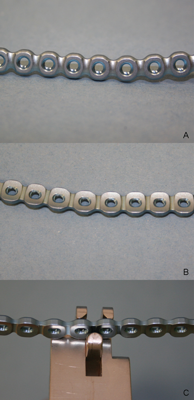
Conventional mandibular reconstruction plates. The notches between the holes are predefined bending points that allow plates to be bent as required. (A) View of the external surface of a 2.5 mm Synthes Matrix Mandible Recon plate. (B) View of the internal surface of a plate. (C) Bending pliers are used to bend the plate at a notch between two screw holes.
The objective of this study was therefore to simulate the entire workflow of computer-assisted mandibular reconstruction that was performed with a patient-specific mandibular reconstruction plate fabricated with CAD/CAM techniques and a fibula flap in a cadaveric wet laboratory. The focus of this study was on the reconstruction plate, which was milled from titanium using a five-axis milling machine. We assessed the feasibility of this method from virtual surgical planning to the completion of surgery in the wet laboratory.
Materials and Methods
Multi-slice computed-tomography (MSCT) scans of a skull and fibula that had been harvested from the same formalin-fixed cadaver donor were obtained (scanning parameters: slice increment 0.5 mm; pixel size 0.366 mm). The scanning parameters recommended by DePuy Synthes® for ProPlan CMF services, however, are: slice thickness max. 1.0 mm, feed per rotation max. 1.0 mm, and reconstructed slice increment max. 1.0 mm.7
Computer-assisted planning started with the virtual simulation of mandibular resection and mandibular reconstruction with a six-segment fibula flap. Planning was performed using ProPlan CMF planning software (Materialise®/DePuy Synthes®). The planning session was held via a Web meeting (GoToMeeting®, Citrix Online, Santa Barbara, CA) between engineers from Materialise® and DePuy Synthes® and the surgeons. During the entire planning session, the engineers operated the computer system and the surgeons gave verbal instructions on the basis of medical requirements. We used a milled patient-specific CAD/CAM-fabricated reconstruction plate together with a six-segment fibula flap for the simulation procedure in an attempt to create a case that was more complex and more challenging than standard cases.
First, the resection planes of the mandible were established (Fig. 2). The size of the mandibular segment that must be resected is usually determined by the extent of the pathology being treated. Clinical findings and especially diagnostic computed-tomography (CT) scans play a key role in this context.
Figure 2.
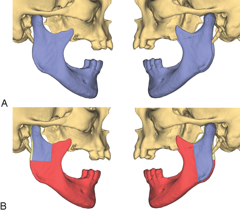
Resection lines in the region of the mandible. (A) Mandible without resection (blue). (B) Planned resection (red) with preservation of the blue segments.
Virtual mandibular resection was followed by the virtual reconstruction of the resultant mandibular defect with a fibula flap consisting of six segments. This semi-automatic procedure involved dividing the mandibular bone defect into six units with a view to positioning the fibula segments in such a way that they would fill the defect in an appropriate manner. After the distal and proximal ends of the fibular osteotomy site were determined, the fibula flap was virtually placed into the defect using a software algorithm (Fig. 3). Since a fibula is a straight bone, wedges must be cut from the bone to allow the desired shape of the mandible to be created. Osteotomy lines and angles were automatically determined by the software (Fig. 4). Following an automatic rough positioning of the pieces of bone, the fibula segments were manually placed in their exact position by the planning engineer at the end of the virtual mandibular reconstruction procedure.
Figure 3.
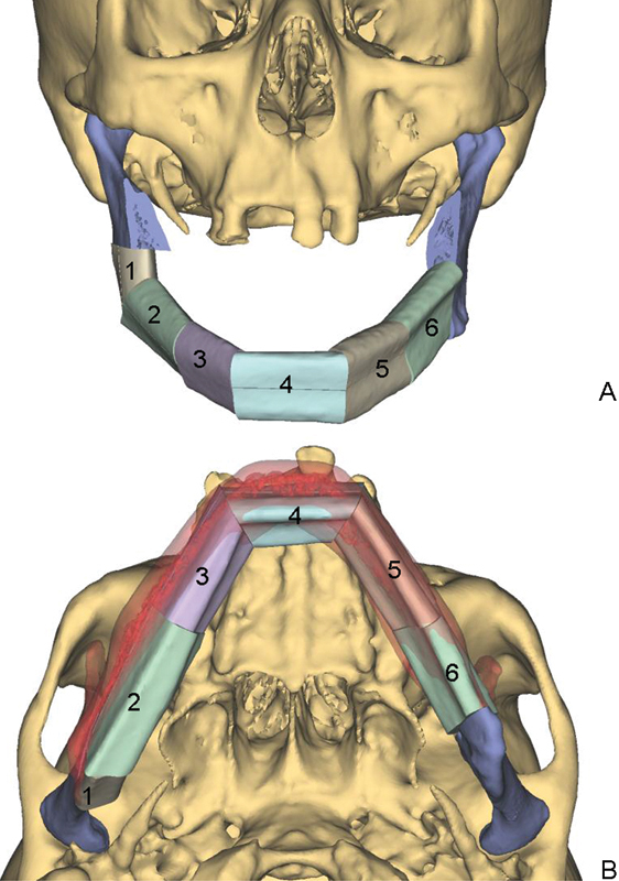
(A) Virtual mandibular reconstruction with a six-segment fibula flap (segments 1 to 6). (B) The original mandible (red) is superimposed over the reconstructed mandible.
Figure 4.

Virtual fibula osteotomy lines. Segments 1 to 6 were used for mandibular reconstructions. Segments a to e are triangular bone segments that had to be removed to obtain the desired shape of the neomandible consisting of segments 1 to 6 (see also Fig. 3).
A virtual model of the reconstructed mandible which had been generated on the basis of computer-aided planning was then used for the computer-aided planning of a reconstruction plate using DePuy Synthes proprietary CAD software. The position of the plate along the outer surface of the virtual mandibular reconstruction model was defined by the (DePuy Snythes) engineer in accordance with the surgeons' wishes. Then a 2.5 mm plate was virtually shaped on the basis of the model using a special software algorithm. Different numbers, sizes and angles (maximum: 15 degrees) of screw holes could be selected (Fig. 5). The plate described here had 24 holes. The holes in the regions of the right and the left ramus were angled (15 degrees) in the craniocaudal direction (Fig. 5). In addition, the required or desired length of each screw was determined by computer simulation. In the case presented here, bicortical screws were placed in the residual mandibular bone and monocortical screws in the fibula segments.
Figure 5.
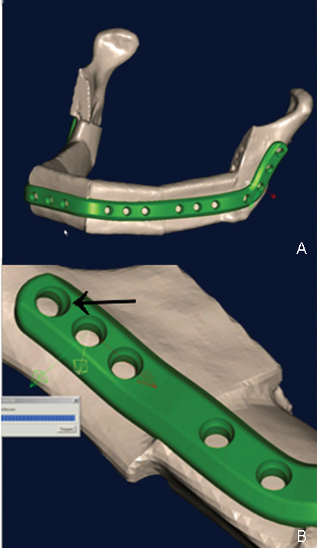
Computer-aided planning of a patient-specific mandibular reconstruction plate. (A) The plate was virtually contoured to the virtually planned model. (B) The number of screws as well as the position and angle of each screw (arrow) were determined as well.
In a next step, resection guides for mandibular resection and cutting guides for harvesting fibula segments were designed using CAD and then laser-sintered from biocompatible polyamide.8 This was done by the software engineers alone after the planning session. The purpose of these guides is to accurately transfer virtual planning of mandibular and fibular osteotomies to surgery (Fig. 6). The screw hole configuration of the virtual plate, i.e., the number of screws as well as the position and angle of each screw, were transferred to the resection and cutting guides. Drill sleeves were integrated into the guides. We were thus able to fix the guides on the mandible and fibula and to predrill the holes for fixing the plate to the residual mandible and for fixing the fibula segments to the patient-specific plate without having to use the plate (Figs. 6, 7 and 9B). The objective of this approach was to ensure that the plate was placed exactly in the planned position especially in the region of the remaining mandibular segments. Particular care was taken to maintain the position of the residual mandibular segments (rami and condyles) and to accurately transfer virtual planning to surgery. After the Web meeting, a final mandibular reconstruction plan was prepared by the engineers from Materialise® and DePuy Synthes® and approved by the surgeons. Whereas the guides were laser-sintered from biocompatible polyamide (Fig. 7), the plate was milled from a piece of titanium alloy using a DePuy Synthes proprietary milling machine and CAM techniques (Fig. 8).
Figure 6.
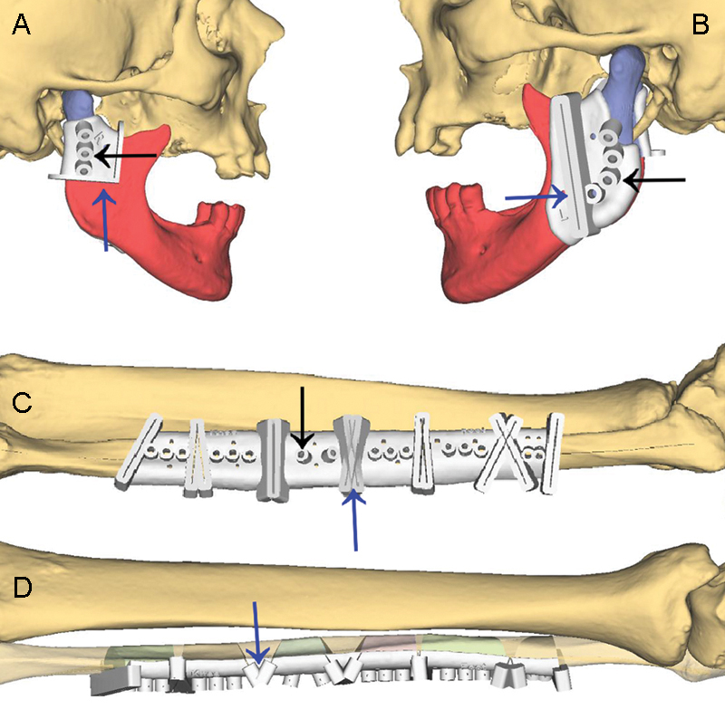
Computer-aided design (CAD) of resection guides for mandibular resection (A and B) and cutting guides for harvesting fibula segments (C and D). Black arrows indicate drill sleeves that were integrated into the guides and identified the screw holes that were used for fixing the plate to the residual mandible and for fixing the fibula segments to the plate. Blue arrows indicate slots and flanges that help surgeons guide an osteotomy saw.
Figure 7.
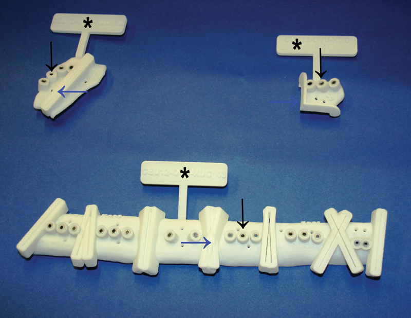
Resection guides (top) and cutting guides (bottom) manufactured with computer-aided manufacturing (CAM) techniques. Black arrows indicate drill sleeves, blue arrows indicate slots and flanges (see also Fig. 6). The guides are still marked with tags (*).
Figure 9.
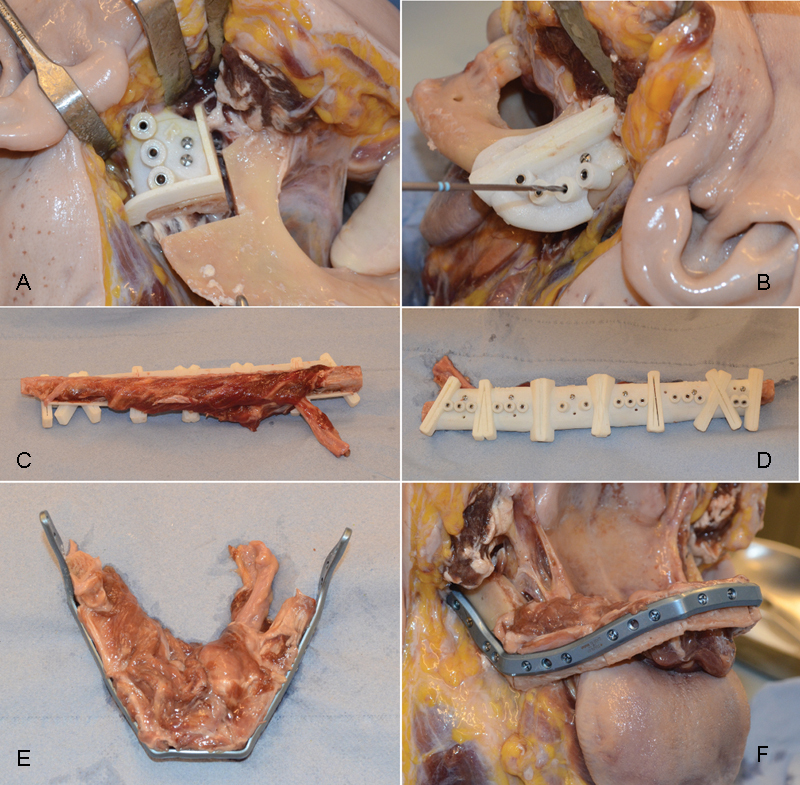
Course of the wet laboratory experiment. (A and B) Resection guides were placed on the right condyle and the left ramus. (A) After osteotomy. (B) Screw holes were predrilled as planned on the basis of the guides. (C and D) A cutting guide was placed on the fibula and fixed with miniscrews. (E) Six fibula segments were obtained on the basis of the cutting guide and were attached to the plate. (F) Completion of the mandibular reconstruction with a fibula flap and a patient-specific reconstruction plate.
Figure 8.
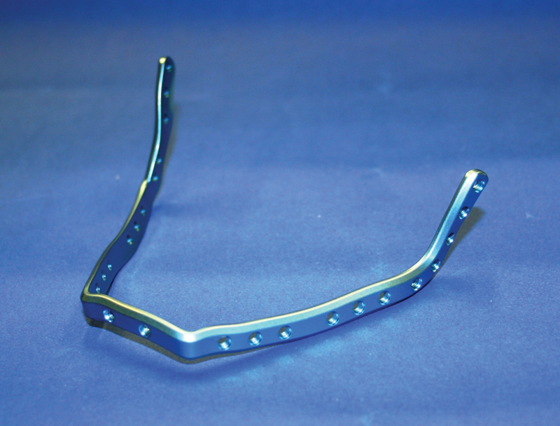
Patient-specific mandibular reconstruction plate milled from titanium.
Finally, the virtually planned mandibular reconstruction was performed using cadaver specimens and assessed in terms of feasibility, practicability, precision and weaknesses. The study adhered to the Declaration of Helsinki and was conducted at the Synthes Innovation Workshop housed at Paracelsus Medical University (PMU - Strubergasse 21, 5020 Salzburg, Austria). Based on a collaboration between PMU and DePuy Synthes®, a human cadaver was obtained from the Institute of Anatomy at PMU. The cadaver donor had consented to the donation of his body for medical research and education. After the study, the cadaver was returned to the Institute of Anatomy.
Results
Fig. 9 provides an overview of the various steps of the cadaver study presented here. The resection guides were placed on the mandible and the cutting guides were placed on the fibula in a clinically appropriate way. In the clinical setting, no problems were encountered in positioning the resection guides on the mandible as planned (Fig. 9A and B). By contrast, the positioning of the cutting guides on the fibula was more difficult. This can be explained by the attachment of soft tissue (periosteum, connective and muscle tissue) to the fibula and the shape of the fibula, which is a straight bone and has no prominent edges or points similar to the mandibular angle. The cutting guides were therefore difficult to position accurately in the distal to proximal direction. Nevertheless, the cutting guides were placed on the fibula in a clinically appropriate way (Fig. 9C and D).
The resection guides allowed us to transfer the virtual resection to a real surgical setting without problems and, as far as we were able to assess clinically, with a high level of accuracy. Following the integration of drill sleeves into the resection guides, we were able to predrill the screw holes for placing and fixing the reconstruction plate as planned without having to use the plate (Fig. 9B). We had no problems in positioning and attaching the plate using the predrilled holes (Fig. 9F). After having harvested fibula segments by means of the cutting guides, we were able to attach the segments to the patient-specific plate easily and rapidly (Fig. 9E). Only minimal corrections, i.e., minor smoothing and trimming of bone, were necessary to maximize precision and to facilitate attaching the fibula segments to the plate.
The fusion of preoperative and postoperative CT datasets showed that the positions of the two residual rami and condyles after the fixation of the CAD/CAM-fabricated reconstruction plate were almost identical to those before resection (Fig. 10). We were thus able to transfer the virtually planned position of the patient-specific CAD/CAM-fabricated reconstruction plate precisely to the site of surgery. Accordingly, there was no dislocation of the residual bone segments (both rami and condyles).
Figure 10.
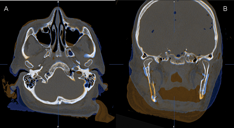
The fusion of preoperative (amber) and postoperative (blue) CT datasets demonstrated that the positions of the two residual rami and condyles after the fixation of the CAD/CAM-fabricated reconstruction plate were almost identical to those before resection. (A) Axial view. (B) Coronal view.
The postoperative CT also shows an almost perfect alignment of the six fibula segments along the CAD/CAM-fabricated reconstruction plate and close contact between the bone segments (Fig. 11). The lengths of the screws had been determined virtually. In the clinical setting, bicortical screws were placed in the residual mandible and monocortical screws in the fibula segments exactly as planned.
Figure 11.
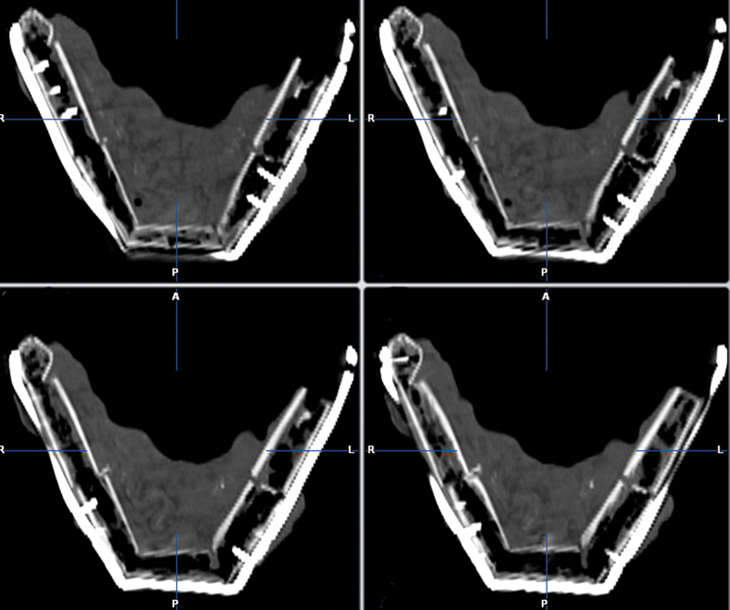
Postoperative CT scan of the reconstructed mandible showing good alignment of the six fibula segments along the CAD/CAM-fabricated reconstruction plate as well as close contact between the bone segments (axial view).
Discussion
The CAD/CAM techniques described here for planning and manufacturing patient-specific mandibular reconstruction plates are a promising approach to improving mandibular reconstruction. We believe that especially the flexibility in contouring the plate and selecting the number, sizes and angles of screw holes in accordance with individual requirements is a major advantage of this method in comparison to the conventional technique of bending plates manually. Since a plate that is manufactured according to a patient's specific needs does not have to be bent and therefore does not require any predefined bending points, it is highly probable that the plate is more stable and more resistant to fracture than currently available fixation plates. Biomechanical tests and especially clinical trials are now required to provide further evidence for this hypothesis.
For the simulation procedure described here, we used a plate that was 2.5 mm thick. In our opinion, however, plates with different thicknesses would be desirable. We believe that plates with different thicknesses would be suitable for different types of mandibular reconstruction. If, for example, plate reconstruction is combined with primary bony reconstruction, maximum plate stability is usually not required. A plate thickness of 2.0 mm, which is meanwhile also available would be sufficient. If, by contrast, only alloplastic materials are used for mandibular reconstruction with or without secondary bony reconstruction, the plate should be as stable as possible to avoid plate fractures. In this case, a plate thickness of 2.5 mm or even 2.8 mm would be appropriate and desirable.
The reconstruction plate has threaded screw holes. These holes accept locking screws that are today used for mandibular reconstruction plates on a standard basis and offer distinct advantages. In our opinion, an added benefit can be gained by using the Synthes® MatrixMANDIBLE™ system. MatrixMANDIBLE™ screws with different diameters (2.0 mm, 2.4 mm and 2.9 mm) and identical screw heads can be used for individually planned plate holes. In addition, non-locking screws can also be used without problems. For example, bicortical screws with a diameter of 2.4 mm or 2.9 mm can be used for the secure fixation of a plate to the residual mandible and screws with a diameter of 2.0 mm can be used for securing a bone flap to the plate. In our opinion, this flexibility offers particular advantages for bony reconstructions.
Different screw hole angles (maximum: 15 degrees) can be selected and can make it easier for surgeons to insert screws in a caudal direction especially in the region of the ascending ramus and the mandibular neck. It is also easier for surgeons to drill such angled screw holes via the commonly used submandibular approach using either resection guides or conventional drill sleeves that are integrated into plates since this technique does not require that soft tissue be retracted to the extent necessary when screw holes are drilled perpendicular to the plate. Nevertheless, we are of the opinion that larger angles, for example an angle as large as 30 degrees, would be desirable. Further tests, however, are required to investigate the technical feasibility of creating screw holes with larger angles especially in combination with locking screws. Angled screw holes in the region of the ascending ramus and the mandibular neck and the resultant oblique orientation of the screw within the bone are associated with an area of contact between cortical bone and the thread of the screw that is larger than that created by straight screw holes. This may lead to an increase in the primary stability of the screws within the bone and may thus improve the stability of the entire system consisting of residual bone, screws and the plate.9 10 At the same time, the risk of screw or plate loosening can possibly be reduced. This is of particular importance when insufficient bone is available after mandibular resection and a maximum of two screws can be inserted in the region of the mandibular neck.
A further possible advantage of CAD/CAM-fabricated patient-specific plates over conventional plates is that a sufficient number of screws can obviously be used for the fixation of the plate even in the presence of insufficient bone because the contour of the plate and the positions of the screw holes can be planned on an individual basis. Currently, however, there are technical limitations since the minimum distance between two screw holes is 5.5 mm. By contrast, the minimum distance between two screw holes is 8 mm for standard plates such as the DePuy Synthes® MatrixMANDIBLE™ Recon plate. At least two screws or, if possible, more than two screws should be used for the stable anchorage of a plate to the residual mandible after resection. By contrast, two monocortical screws are completely sufficient for fixing bone flaps. In this case, the use of two screws is not absolutely necessary but is recommended to avoid flap rotation.
The standard procedure for plate fixation or repositioning can usually not be used in the case of reconstruction plates that were precontoured in accordance with preoperative planning. This applies to many situations and in particular to bony reconstructions with fibula flaps. A typical example would be a malignant tumor that expands through the outer cortical bone of the mandible and must be resected with adequate margins. Likewise, a standard procedure can be impossible in the management of extensive benign lesions such as cysts or ameloblastomas. The standard procedure usually involves the temporary fixation of a plate to the native mandible prior to resection and thus prior to the loss of mandibular continuity. For this purpose, at least two holes must be predrilled in the distal and proximal mandibular segments and screws are usually inserted. The plate is removed before resection and again fixed to the residual mandible after resection using the predefined screw holes. This procedure helps surgeons ensure as accurately as possible that the plate is fixed to the residual bone in the same position as before resection.11
When this procedure is used, the plate, which can be bent intraoperatively or prebent preoperatively using a patient-specific model, can be shaped only to the contour of the mandibular surface. In the majority of cases, the plate is aligned to the lateral inferior border of the body of the mandible and to the lateral posterior border of the ascending ramus. Plates, however, can also be contoured to the lower surface or even the internal surface of the mandible. The method presented here involves positioning the plate by means of the screw holes that had been virtually planned and integrated into the resection guides (Fig. 9B). The principles underlying this method are the same as those behind the aforementioned standard procedure, which also uses screw holes to define the definitive position of the plate on the residual mandible. The difference is that we made primarily use not of the plate but of guides to define and transfer screw holes positions.
The fusion of preoperative and postoperative CT datasets (Fig. 10) demonstrates that an accurate positioning of the plate on the basis of planning is possible and that the dimensions of the mandible and the positions of the residual mandibular segments can thus be maintained. In our opinion, this plays an important role in maintaining or restoring temporomandibular joint (TMJ) function and occlusion in patients who still have occluding teeth after mandibular resection and reconstruction.
Precision depends on the exact positioning of the resection guides on the mandibular bone. Important factors influencing repositioning are the design of the guide, especially the size of the guide, and the location where the guide must be placed on the mandible. Our own clinical experience with the positioning of guides during procedures that did not involve the use of CAD/CAM-fabricated patient-specific plates has shown that the accurate positioning of guides is relatively easy in the region of the mandibular angle and considerably more difficult in the region of the ascending ramus and the mandibular neck. Whereas the guides can usually be designed in such a manner that they encompass the posterior mandibular neck and can be attached anteriorly in the region of the mandibular notch, they are still difficult to position at this site via the commonly used submandibular approach as a result of limited visibility during surgery. Contrary to expectations, it is difficult for surgeons to position guides in the region of the mandibular body and especially in the region of the lateral mandible. Although visibility is usually not limited in this area, the accurate position of the guides cannot always be reliably defined. The reason for these difficulties is the uncharacteristic and smooth surface of the mandible in this region. As a result, there are sometimes several guide positions that appear to be clinically correct. Larger guides and/or the integration of information about the site of exit of the mental nerve can be helpful.
The method presented here may also benefit from planning the entire mandibular reconstruction backward. This approach is well known from the field of dental implantology and involves planning reconstruction backward from virtual prosthetic planning to dental rehabilitation. The planning of bony reconstruction is determined by the position of the dental implant, which depends on prosthetic aspects, and the design of the plate is determined by bony reconstruction. Backward planning is generally possible in both primary and secondary bony reconstructions. A primary alloplastic reconstruction with a CAD/CAM-fabricated plate, however, should be planned together with a virtual bony reconstruction. This applies in particular to procedures that are performed by surgeons with a low level of experience. Such a procedure has been described by Essig et al.12
One disadvantage of this new approach is the time required for planning (approximately one hour) and for producing and delivering the CAD/CAM-fabricated plate (at least ten working days). Whereas the Web meetings and thus planning will likely require less time once planning has become a routine procedure for surgeons and engineers, the time for manufacturing and logistic services can hardly be reduced. We must therefore realistically assume that the minimum time from the decision about the surgical approach to be used and the surgical procedure will be approximately twelve to fourteen days. Any delays in the workflow can result in the postponement of urgent surgical procedures such as tumor resection. By contrast, planning time is unlikely to affect secondary reconstructions and the management of benign diseases.
The costs of the reconstruction method presented here must be discussed as well. Unfortunately, we cannot give exact costs. To our knowledge, the costs of a computer-assisted mandibular reconstruction with resection and cutting guides and a manually prebent plate amount to approximately EUR 2500 to EUR 3000 in Europe. Since patient-specific CAD/CAM-fabricated plates are not yet available on the market, we do not know how much the extra cost will be. Extra material costs, however, must be considered in the light of potential benefits such as predictability of outcome, a possible decrease in complications, and high reconstruction quality.
Conclusions
Computer-assisted mandibular reconstruction with patient-specific CAD/CAM-fabricated mandibular reconstruction plates appears to be a promising approach to reconstructing mandibular defects. A high quality of reconstructions especially in terms of form and function can be expected. Clinical trials are required to determine whether these promising results can be translated into successful practice and what further developments are needed in the future.
Acknowledgments
The entire study was financed and supported by DePuy Synthes®.
References
- 1.Markiewicz M R Bell R B The use of 3D imaging tools in facial plastic surgery Facial Plast Surg Clin North Am 2011194655–682., ix [DOI] [PubMed] [Google Scholar]
- 2.Haddock N T, Monaco C, Weimer K A, Hirsch D L, Levine J P, Saadeh P B. Increasing bony contact and overlap with computer-designed offset cuts in free fibula mandible reconstruction. J Craniofac Surg. 2012;23(6):1592–1595. doi: 10.1097/SCS.0b013e318257576c. [DOI] [PubMed] [Google Scholar]
- 3.Levine J P, Patel A, Saadeh P B, Hirsch D L. Computer-aided design and manufacturing in craniomaxillofacial surgery: the new state of the art. J Craniofac Surg. 2012;23(1):288–293. doi: 10.1097/SCS.0b013e318241ba92. [DOI] [PubMed] [Google Scholar]
- 4.Roser S M, Ramachandra S, Blair H. et al. The accuracy of virtual surgical planning in free fibula mandibular reconstruction: comparison of planned and final results. J Oral Maxillofac Surg. 2010;68(11):2824–2832. doi: 10.1016/j.joms.2010.06.177. [DOI] [PubMed] [Google Scholar]
- 5.Hidalgo D A. Titanium miniplate fixation in free flap mandible reconstruction. 1989;23:498–507. doi: 10.1097/00000637-198912000-00005. [DOI] [PubMed] [Google Scholar]
- 6.Yadav P S, Gazwan Q A, Shankhdhar V K, Nambi G I. A simple and cost effective template for central segment reconstruction of mandible with free fibula flap. J Maxillofac Oral Surg. 2010;9(3):256–260. doi: 10.1007/s12663-010-0077-9. [DOI] [PMC free article] [PubMed] [Google Scholar]
- 7.CT Scanning Protocol for Synthes ProPlan CMF Products and Services http://sites.synthes.com/MediaBin/International%20DATA/036.001.354.pdf. Accessed January 13
- 8.Synthes ProPlan CMF. Polyamide ProPlan CMF Guides and Models http://cranio-maxillofacial.materialise.com/sites/default/files/public/media/f-mprod-119_synthes_instructions_for_use_polyamide_guides_models_translations_eu.pdf. Accessed January 13
- 9.Shah A H, Behrents R G, Kim K B, Kyung H M, Buschang P H. Effects of screw and host factors on insertion torque and pullout strength. Angle Orthod. 2012;82(4):603–610. doi: 10.2319/070111-427.1. [DOI] [PMC free article] [PubMed] [Google Scholar]
- 10.Thiele O C, Eckhardt C, Linke B, Schneider E, Lill C A. Factors affecting the stability of screws in human cortical osteoporotic bone: a cadaver study. J Bone Joint Surg Br. 2007;89(5):701–705. doi: 10.1302/0301-620X.89B5.18504. [DOI] [PubMed] [Google Scholar]
- 11.Wilde F, Plail M, Riese C, Schramm A, Winter K. Mandible reconstruction with patient-specific pre-bent reconstruction plates: comparison of a transfer key method to the standard method—results of an in vitro study. Int J CARS. 2012;7(1):57–63. doi: 10.1007/s11548-011-0599-8. [DOI] [PubMed] [Google Scholar]
- 12.Essig H, Rana M, Kokemueller H. et al. Pre-operative planning for mandibular reconstruction - a full digital planning workflow resulting in a patient specific reconstruction. Head Neck Oncol. 2011;3:45. doi: 10.1186/1758-3284-3-45. [DOI] [PMC free article] [PubMed] [Google Scholar]


