Abstract
The current technique for cochlear implantation (CI) surgery requires a mastoidectomy to gain access to the cochlea for electrode array insertion. It has been shown that microstereotactic frames can enable an image-guided, minimally invasive approach to CI surgery called percutaneous cochlear implantation (PCI) that uses a single drill hole for electrode array insertion, avoiding a more invasive mastoidectomy. Current clinical methods for electrode array insertion are not compatible with PCI surgery because they require a mastoidectomy to access the cochlea; thus, we have developed a manually operated electrode array insertion tool that can be deployed through a PCI drill hole. The tool can be adjusted using a preoperative CT scan for accurate execution of the advance off-stylet (AOS) insertion technique and requires less skill to operate than is currently required to implant electrode arrays. We performed three cadaver insertion experiments using the AOS technique and determined that all insertions were successful using CT and microdissection.
Keywords: Advance off-stylet (AOS), cochlear implant, image-guided surgery, minimally invasive surgery, percutaneous cochlear implantation (PCI)
I. Introduction
Cochlear implantation (CI) surgery is the current standard of care to treat profound sensorineural hearing loss. An electrode array is inserted into the scala tympani lumen of the cochlea to directly stimulate spiral ganglion neurons, bypassing the middle ear and hair cells. A wire connects the electrode array to a subcutaneous receiver/stimulator unit which receives radio frequency signals from an external microphone and speech processor, as shown in Fig. 1.
Fig. 1.

Cochlear implant system. Sound is detected with an external microphone and transmitted electromagnetically through the skin to a subcutaneous receiver/stimulator, which delivers electrical impulses to an array of electrodes implanted within the cochlea. Image credit: National Institute of Health/Department of Health and Human Services.
To expose the cochlea for electrode array insertion, CI surgery begins with a mastoidectomy. This invasive procedure requires excavating bone posteriorly to the auditory canal using a hand-held surgical drill. Several delicate anatomical structures must be avoided when drilling this approximately 35-mm-deep cavity, including the facial nerve, chorda tympani nerve, and ear canal. Damage to the facial nerve may cause permanent facial paralysis, damage to the chorda tympani may alter the sense of taste, and encroachment of the ear canal may result in infection. Specially trained surgeons must rely on a 3-D mental map and hand-eye coordination to avoid harming these structures. There is acute risk of nerve damage at the facial recess, where the facial nerve and chorda tympani are separated by as little as 2.4 mm [1]. The drill and electrode array must pass through this narrow passage to enter the middle ear and reach the cochlea.
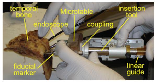
A new minimally invasive, image-guided surgical technique called “percutaneous cochlear implantation” (PCI) has been developed by Labadie et al. to gain access to the cochlea without a mastoidectomy, reducing the invasiveness of traditional CI surgery and potentially reducing the duration of surgery [2], [3]. Prior to PCI surgery, three fiducial markers are implanted into the patient’s skull and a CT scan of the temporal bone is acquired. Custom software is used to automatically segment the critical anatomy, and plan a safe drill trajectory from the lateral skull to the cochlea [4]-[6], and localize the fiducial markers. A patient-customized microstereotactic frame known as a Microtable, shown in Fig. 2, is then manufactured from Ultem (polyetherimide) using a computer numerical control (CNC) milling machine in less than 4 min, sterilized, and then attached to the fiducial markers. A coupling on the Microtable allows attachment of a surgical drill mounted on a linear slide with a mechanical stop set at the depth of the planned cochlear target [7]. The linear slide constrains drill motion to the planned trajectory, allowing the surgeon to reach the cochlea using a straight pushing motion rather than by performing a mastoidectomy. A targeting accuracy of 0.37 mm ± 0.18 mm has been demonstrated with the Microtable [2], and PCI is currently under clinical evaluation [3].
Fig. 2.
The microtable is a microstereotactic frame that serves to constrain a surgical drill to a linear trajectory from the lateral cranium through the facial recess to the cochlea. Each Microtable is custom-manufactured in less than 4 min using data obtained by automatic processing of a preoperative CT scan, and has a mechanical coupling for attachment of additional tools.
As an alternative to Microtable fabrication, we have introduced a bone-attached parallel robot as an automated microstereotactic frame for PCI [8], and investigated the use of industrial serial robots to drill a hole for PCI [9]. Kobler et al. [10] proposed a manually adjusted Gough-Stewart platform for minimally invasive CI surgery which attaches directly to the skull. Majdani et al. [11] tested an industrial robot for drilling to the cochlea, and Bell et al. [12] developed a serial robot for PCI surgery. Each of these approaches addresses the drilling portion of PCI surgery, but does not solve the problem of inserting electrode arrays through a drill hole.
To insert the electrode array into the scala tympani, a small hole called a cochleostomy is created in or near the round window of the cochlea. Prior to the availability of precurled electrode arrays, straight electrode arrays were pushed into the cochlea and would bend into a spiral shape due to contact forces with the walls of the scala tympani. Contact forces with the walls of the scala tympani can cause intracochlear trauma that are believed to reduce residual acoustic hearing [13] and electrode array crossover into the scala vestibuli likely has a detrimental effect on cochlear implant performance [14], [15]. Rebscher et al. suggested adding a stiffening rib to an electrode array to reduce intracochlear trauma [16], but implants with this feature are not yet clinically available. Zhang et al. proposed steerable electrode arrays to reduce trauma and buckling that can be deployed along optimally planned trajectories and mounted to a force-sensing robot [17], but these devices have not been adapted for PCI surgery and are not yet clinically available.
One clinically approved method for reducing intracochlear trauma is called advance off-stylet (AOS) insertion [18], [19]. An AOS electrode array is precurled to hug the medial wall of the cochlea, also known as the modiolus, which contains a dense network of spiral ganglion neurons. The electrode array is straightened prior to insertion using a stiff wire called a stylet that is preinserted into a central channel of the array. The straightened array is inserted up to the basal turn of the scala tympani, which is indicated by a mark on the electrode array. Stylet advancement continues at this point with the array being pushed off of the stationary stylet, regaining its curled shape.
Specialized tools for array insertion are supplied by cochlear implant manufacturers for use with specific implant models [20]. The Nucleus 24 Contour Advance (NCA) electrode array from Cochlear Corporation (Sydney, Australia) is supplied with cupped forceps to grip and advance the implant, while jeweler’s forceps held in the opposite hand are used to grasp the stylet for AOS insertion. Advanced Bionics Corporation (Valencia, CA) provides insertion mechanisms for the HiFocus Helix and HiFocus 1j electrode arrays to allow AOS insertion, with a separate claw tool used to detach the electrode arrays from the insertion tools after the arrays have been implanted in the cochlea. Med-El Corporation (Innsbruck, Austria) manufactures angled forceps to grasp electrode arrays that prevent excess clamping force and are used with a straight insertion technique.
Existing electrode array insertion tools are not suitable for PCI surgery because they are designed for maneuverability within a relatively large mastoidectomy cavity and not within the approximately 1.5-mm diameter drill hole created for PCI surgery. Furthermore, existing insertion tools require reliance on the surgeon’s hand-eye coordination to maintain the proper position and orientation of the array during insertion. Though the effects of hand tremor, positional error, and angular error on CI surgical outcomes are not known, eliminating these effects by stabilizing the electrode array throughout insertion may reduce trauma and enable more accurate electrode placement.
Previous efforts to develop a PCI-compatible insertion tool have included a robotic device called an “Automated Insertion Tool” [21]-[23], using two linear actuators to manipulate both an electrode and stylet for AOS insertion. Automatic insertion devices may eventually be proven advantageous to manually operated insertion approaches, but such devices are likely to face regulatory challenges and slow clinical acceptance due to safety concerns. To expedite availability of PCI surgery, we have recently pursued development of a manually powered electrode array insertion tool [24] for AOS insertion. In this paper, we introduce an improved design of the manual, AOS insertion tool and present results from three ex vivo cadaver insertions performed using the tool.
II. Insertion Tool Design
The narrow drill hole created for PCI surgery limits possible mechanisms for advancing the electrode array into the cochlea while grasping the stylet. Bulky linkages and grippers cannot fit in this hole, and mechanisms that are difficult to operate would contravene our goal of simplifying CI using the PCI approach. To satisfy these constraints, we have designed an electrode array insertion tool that uses a compact concentric tube mechanism that fits within the PCI hole, performs AOS insertion with a single push of the hand, and allows fine adjustment of the stylet insertion depth.
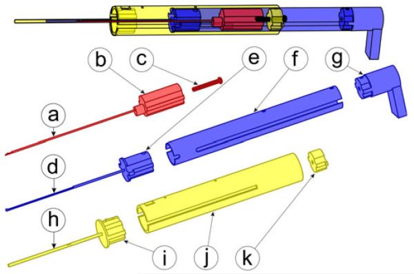
Our insertion tool includes three main components: a guide assembly, an electrode array pusher, and a stylet arrestor. These components are made from autoclavable stainless steel and Ultem parts, shown in Fig. 4, with a total cost of less than US$50.
Fig. 4.
Insertion tool includes three main components, each built from stainless steel and Ultem. The stylet arrestor hooks to the stylet handle to enable AOS insertion and includes (a) a steel stylet latching tube, (b) an Ultem plunger, and (c) a stylet adjustment set screw. The electrode array pusher drives the electrode array into the cochlea and includes (d) a steel driver tube, (e) an Ultem spacer, (f) a steel piston tube, and (g) a thumb rest. The guide assembly includes (h) a steel containment tube, (i) an Ultem spacer, (j) a steel guide tube, and (k) an Ultem set screw catch.
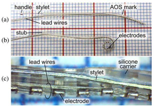
We have customized the insertion tool for use with the precurled NCA electrode (Cochlear Corporation, Melbourne, Australia), but the tool could be modified for use with other cochlear implant models. The NCA electrode, shown in Fig. 3, is approximately 0.5 mm at the apical end and widens to 0.8 mm at the proximal end, and is delivered with a preinserted stylet with a small metal handle at the exposed end. The stylet straightens the precurled array for AOS insertion. The fine electrical wires connecting the array to the receiver/stimulator protrude from one side of the proximal end of the array. The proximal end terminates in a short stub without sensitive wires inside that is grasped by cupped forceps in current clinical usage. Our tool utilizes the flat face of this stub as a pushing surface to advance the electrode array. The side of the array opposite to the wire attachment contains 22 intracochlear electrodes and is designed for perimodiolar placement. Thus, it is necessary to control the angle of the array about the insertion axis to correctly place the electrodes.
Fig. 3.
(a) NCA electrode array preinserted with a stylet, shown on a 1-mm grid. (b) After insertion, the stylet is removed and the electrode array returns to a coiled shape, causing electrodes to rest in close proximity to the modiolus. (c) Magnified view of a section of the electrode array.
The guide assembly, shown in Fig. 4(h)–(k), houses the remaining two moving components and constrains them to travel along the linear insertion trajectory. It is constructed from a 16 mm outer diameter stainless steel housing tube attached via an Ultem spacer to a 1.47 mm outer diameter (#17 hypodermic needle gauge) containment tube. The containment tube fits within the PCI drill hole and provides a closed channel through the middle ear cavity as shown in Fig. 10(a), preventing accidental deployment into this space.
Fig. 10.
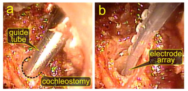
Endoscopic visualization of electrode array insertion in specimen 1. (a) View of the containment tube of the insertion tool positioned at the cochleostomy hole to begin insertion. (b) After removal of the insertion tool, the electrode array is fully placed in the cochlea.
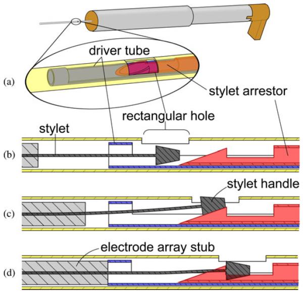
A slot along the length of the containment tube permits the extension of the electrode array containing the bundle of receiver wires to be routed outside of the insertion tool, avoiding high stresses on the wires. The slot also determines the angle of the array about the axis of insertion. The slot angle is a parameter of Microtable design, and is automatically chosen by our Microtable design software based on the geometry of the scala tympani such that the electrode array will curl in the correct plane around the modiolus. The side of the containment tube opposite the slot has a small rectangular hole, as shown in Fig. 5. During tool loading, the tip of the stylet latching tube can only be attached to the stylet handle when the latter is visible within the rectangular hole, ensuring that the electrode array is loaded to the prescribed height within the containment tube. The technique for loading the electrode array is explained in Section III.
Fig. 5.
Stylet latching mechanism securely grasps the small handle of the NCA electrode stylet for AOS insertion. (a) Oblique view of concentric components within the containment tube, rendered transparently. (b) To load the stylet, the electrode array is pushed into the containment tube until the stylet handle is visible in the rectangular hole. (c) Electrode array pusher is advanced until (d) the stylet handle is observed by the user to be latched by the tip of the stylet latching tube.
The electrode array pusher extrudes the electrode array out of the end of containment tube and into the cochlea and is shown in Fig. 4(d)-(g). A 14 mm outer diameter steel piston tube capped with an Ultem thumb rest slides within the outer guide tube, and is connected by an Ultem spacer to a 1.07 mm (#19 hypodermic needle gauge) outer diameter driver tube that pushes against the stub on the proximal end of the electrode array and slides concentrically within the containment tube.
The purpose of the stylet arrestor is to halt stylet advancement with respect to the advancing electrode array to execute the AOS insertion technique. This component, shown in Fig. 4(a)-(c), consists of an Ultem plunger connected to a 0.81 mm (#21 hypodermic needle gauge) outer diameter stainless steel latching tube. The plunger slides within the 14 mm outer diameter section of the electrode array pusher, and the 0.81 mm tube slides within the driver tube of the electrode array pusher. A mechanism at the distal end of the latching tube grasps the small metal handle at the end of the stylet wire, as illustrated in Fig. 5.
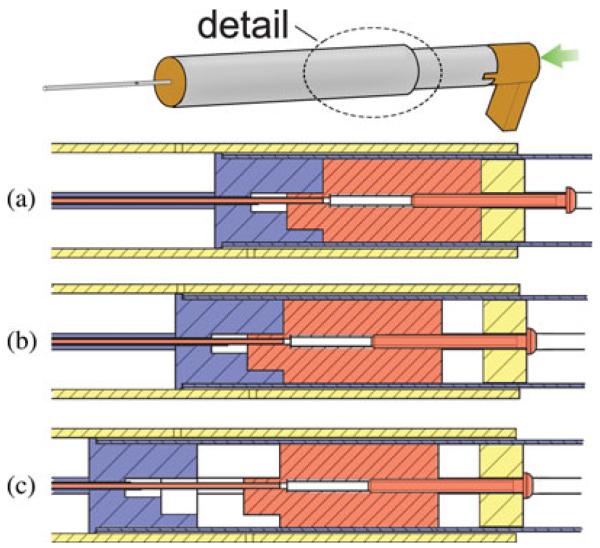
A set screw is threaded into the top of the stylet arrestor plunger and is used to set the length of stylet wire that enters the cochlea. The insertion depth may be selected from implant specifications or customized for an individual patient’s scala tympani anatomy. At the beginning of insertion, with the electrode array pusher partially withdrawn from the guide tube, the plunger component of the stylet arrestor is frictionally mated to the top of the Ultem spacer of the electrode array pusher. When the head of the set screw engages the catch on the top of the guide assembly, the Ultem spacer separates from the immobilized plunger, halting further stylet advancement. Fig. 6 illustrates this motion sequence.
Fig. 6.
AOS insertion is achieved with a single pushing motion. (a) Plunger and the spacer of the electrode array pusher are temporarily connected at the beginning of insertion by a frictional fit. (b) Advancing the electrode array pusher also advances the stylet arrestor plunger. (c) Upon reaching the preset stylet insertion depth, the set screw catch stops further advancement of the plunger, allowing the electrode array to be pushed off the stylet.
III. Tool Loading and Operation
The insertion tool is designed for use in PCI surgery after drilling has been completed and the drill has been removed from the Microtable.
Prior to insertion, an electrode array is loaded by hand into the presterilized tool and then the stylet is latched to the stylet arrestor as illustrated in Fig. 5. To load the electrode array, the electrode array pusher is partially withdrawn from the guide assembly to clear the driver tube from the containment tube. The stub end of the electrode array is manually inserted into the open end of the containment tube until the stylet handle is visible in the rectangular window. The thumb rest is then slowly advanced until the operator observes the latching mechanism at the tip of the stylet arrestor attaching to the stylet handle.
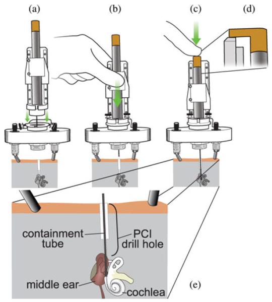
After the electrode array is loaded in the tool, the entire tool is clamped to the moving carriage of a linear slide mechanism. Next, the stationary base of the linear slide mechanism is attached to a coupling on the microtable, as shown in Fig. 7(a). The linear slide constrains the motion of the insertion tool to be concentric with the PCI drill hole, as shown in Fig. 7(b), and has a mechanical stop to halt advancement when the tip of the containment tube is positioned at the cochleostomy hole, which has been previously drilled. We chose the linear slide mechanism because it has been clinically validated for accurate drill guidance during PCI surgery [3], suggesting that it can also provide accurate guidance for the insertion tool, which is deployed along the same path followed by the drill.
Fig. 7.
Operation of the manual insertion tool. (a) After the drill has been removed from the Microtable, a linear slide holding the insertion tool is attached to the Microtable. (b) Linear slide carriage is advanced until reaching a mechanical stop, bringing the containment tube opening to the cochleostomy. (c) Push tube handle is pressed to perform AOS insertion of the electrode array into the cochlea. (d) Side view of thumb rest contacting the top ledge of the linear slide at full insertion depth. (e) Enlarged view of containment tube placement within the temporal bone.
To perform the insertion, the surgeon slowly advances the electrode array pusher until it reaches its end of travel, which occurs when the thumb rest contacts a ledge on the linear slide mechanism, as shown in Fig. 7(d). During this motion, it is essential that the surgeon stop advancement if tactile feedback indicates that intracochlear trauma or tip foldover is likely. The tool is then removed by slowly raising the linear slide to extract the insertion tool from the drill hole and then detaching the slide/insertion tool from the coupling. The thumb rest must be held in place while doing this to completely remove the stylet and not accidentally pull back the entire array. The total time required to load, use, and remove the insertion tool is typically less than 5 min.
IV. Validation Method
We performed three AOS insertions on formalin-fixed, cadaveric temporal bone specimens using the electrode array insertion tool shown in Fig. 8 with NCA practice electrodes. We previously introduced the following test procedure in [25], and the same steps are intended to be performed clinically when implementing PCI surgery (autoclave sterilization was omitted for cadaver experiments, however), and would be followed by receiver placement and skin incision closure.
Preoperative CT scan: A temporal bone CT scan of the specimen is obtained using a 16-slice Philips Mx8000 IDT 16 CT scanner that provides images with a voxel size of 0.25 mm × 0.25 mm × 0.4 mm.
Trajectory planning: Before surgery, critical structures in the temporal bone such as the cochlea, the facial nerve, the chorda tympani, the ossicles, the labyrinth, and the external auditory canal are automatically segmented in the preoperative CT scan using planning software [4], [5]. The software chooses a safe drill trajectory to the scala tympani, avoiding damage to all critical structures [6]. Fig. 9 shows an example of segmented structures with a drill/insertion tool trajectory for a patient. It takes approximately 3 min to complete this step with an Intel Xeon 2.4-GHz dual quad-core 64-bit computer with 10 GB random access memory. Prior to surgery, figures representing the planned drill trajectory and segmented anatomical structures are superimposed on a CT scan that is visually inspected by the surgeon for safety verification.
Preoperative insertion tool adjustment: The distance from the insertion start point to the basal turn of the scala tympani is measured by voxel interpolation using the planning software. The surgeon then either chooses the standard AOS insertion depth (corresponding to the depth of the white mark on an NCA electrode array that indicates the manufacturer’s recommended AOS insertion depth), or manually chooses a different depth if the standard depth appears suboptimal for a particular specimen’s anatomy. The insertion tool stylet adjustment screw is then adjusted to the chosen depth.
Fiducial marker implantation: Three titanium bone anchors are screwed into the temporal bone surrounding the ear. A titanium extender with a spherical top is screwed into a threaded opening on the exposed top of each anchor. The spherical tops serve both as fiducial markers and as mounting surfaces for a Microtable, which has special gripping mechanisms that attach to the spherical markers.
Intraoperative CT scan: An intraoperative temporal bone CT scan is acquired using an xCAT ENT portable CT scanner (Xoran Technologies, Ann Arbor, MI) with an isotropic voxel volume of 0.4 mm3. This scan includes the temporal bone with implanted markers.
Intraoperative planning: The preoperative and the intraoperative CT scans are rigidly registered using the standard mutual-information method [3], [26]. The segmentations and the desired drill trajectory are transformed from the preoperative scan to the intraoperative scan using the transformation resulting from the rigid registration. Next, the centers of the spherical fiducial markers are localized in the intraoperative scan.
Microtable design and fabrication: A Microtable is automatically designed using custom MATLAB (Mathworks, Natick, MA) software, fabricated using a CNC milling machine, hand-assembled, and examined for accuracy [2].
Drilling to the cochlea: A linear slide with an attached surgical drill is connected to the mechanical coupling in the target hole of the Microtable, and then the Microtable with attached linear slide is mounted on the fiducial markers. Drilling is completed by manually advancing the drill along its constrained linear trajectory using the technique described in [7].
Cochleostomy: The cochleostomy is created using 1.98-mm diameter twist drill bit, and then the linear slide and drill are removed from the coupling on the Microtable.
Electrode array insertion: Electrode array insertion and tool removal are performed as described in Section III. If electrode array placement is confirmed using a second intraoperative CT scan and normal audiometric recordings are made (i.e., impedance testing and neural response telemetry), the securing of the cochleostomy can be performed with transtympanic endoscopic guidance by 1) ensuring that the diameter of the cochleostomy is slightly less than the position of the electrode array resting in the cochleostomy or 2) placing a piece of soft tissue (e.g., fascia) over the cochleostomy/electrode array interface to seal the cochleostomy. Finally, the Microtable is removed from the markers, and the markers are removed from the skull. We did not perform audiometric testing or secure the electrode array with soft tissue in our ex vivo experiments.
Fig. 8.
Experimental insertions were performed using Microtables customized for cadaveric temporal bone specimens using the technique developed for PCI surgery. A Microtable was used to drill to the cochlea of each specimen, and then the insertion tool was attached to a linear slide and mounted to each Microtable for electrode array insertion.
Fig. 9.
Preoperative planning software automatically segments vital structures and determines an optimally safe trajectory from the lateral skull to the cochlea. This trajectory is used both for drilling to the cochlea and for the electrode array insertion tool. The software is also used to customize the stylet insertion depth and to determine the proper angle of the electrode array about the insertion axis.
V. Results and Discussion
In each of the three cadaveric temporal bone specimens, electrode arrays were inserted successfully. Prior to electrode array insertion, an endoscope was used to inspect the drill path in each specimen. For each specimen, we confirmed that the drill correctly reached its desired location and successfully performed the cochleostomy. The postdrilling CT scans revealed no injury to the facial nerve or to the chorda tympani.
A tympanomeatal flap was raised in all samples for endoscopic visualization of electrode array insertion. Endoscopic images of insertion in specimen 1 are shown in Fig. 10. In each case, the insertion tool was fully inserted and appropriate starting location (containment tube tip abutting the cochleostomy) was confirmed using a transtympanic endoscope. Fig. 10(a) shows the placement of the tool tip for insertion. The endoscope remained in place while the insertion tool was removed to visually confirm full electrode array insertion [see Fig. 10(b)].
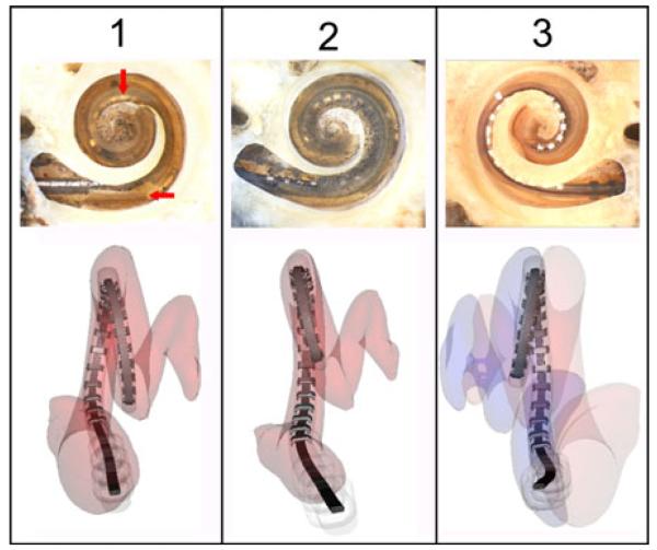
To determine the positions of the implanted electrode arrays, postoperative CT scans were automatically processed using the method introduced by Noble et al. [27], [28], and microdissection analysis [29] was performed on each cochlea, and images from both analyses are shown in Fig. 11. In specimen 1, a small section of the osseous lamina was violated at the electrode array insertion site. However, the array was entirely within the scala tympani with good perimodiolar position. Specimen 2 revealed similar findings with complete scala tympani insertion. However, a similar basal osseous lamina defect is visible. In specimen 3, the electrode was placed entirely within the scala vestibuli without any signs of injury to the osseous lamina. In all specimens, the positions of the electrode arrays identified using the automatic technique matched that of the microdissection analysis.
Fig. 11.
Postoperative results from three cadaveric temporal bone specimens implanted with electrode arrays using the manual insertion tool. (Top row) Microdissection images (created by C.G. Wright, University of Texas Southwestern Medical Center) (Bottom row) Reconstructions of electrode array positions using an automatic segmentation technique. For specimen 1, the electrode array was entirely within the scala tympani. The horizontal arrow indicates part of the osseous lamina injured during implantation and vertical arrow indicates contact with the modiolus. Specimen 2 had a similar defect in the osseous lamina, and the electrode array was also fully implanted in the scala tympani. In specimen 3, the electrodes were implanted lying on the osseous lamina in the scala vestibuli.
The limited trauma observed in specimens 1 and 2 appears similar to that reported in histopathological studies of insertions performed with perimodiolar electrode arrays using current clinical insertion techniques [30]-[32], although more experiments are needed to make conclusive comparisons between results obtained with our insertion tool and current clinical practices.
Dislocation of electrode arrays from the scala tympani to the scala vestibuli as observed in specimen 3 occurs relatively frequently. Clinical data on the rupture of the basilar membrane with crossover from one scala to the other occur in over 33% of cases [14], [15], [33], [34]. Placement in the scala vestibuli is considered undesirable for patients with normal intracochlear anatomy, though typically results in a functional implant [35].
VI. Conclusion and Future Work
We have presented a manually operated tool for image-guided insertion of electrode arrays into the cochlea through a single drill hole during PCI surgery, avoiding the need for the invasive mastoidectomy that is currently required for CI surgery and reducing the skill required to accurately implant electrode arrays. The tool is positioned at the opening of the scala tympani using a Microtable, which we have previously shown to be a safe and accurate method for accessing the cochlea. To validate the tool, we inserted electrode arrays into three cadaveric cochleae using the same workflow that would be used clinically in PCI surgery and confirmed that each insertion would result in a functioning implant.
The mechanical design of our tool allows AOS insertion with a single pushing motion along a constrained trajectory until a fixed stop is reached, and thus requires much less skill to operate than existing insertion instruments. We customized the stylet insertion depth to align with the basal turn of the scala tympani during our cadaveric insertion experiments, providing a degree of control that is not currently available to surgeons. We believe the ability to precisely adjust the stylet insertion depth will result in less insertion trauma, and plan additional experiments with a larger sample to investigate this hypothesis.
We believe that the trauma observed in Fig. 11 is associated with our experimental setup where we drilled directly into the cochlea using a twist drill bit. We hypothesize that the shearing action of the drill bit caused a fracture of the osseous spiral lamina, as noted by the horizontal arrow in that figure. To reduce such trauma, we are investigating other methods of creating a cochleostomy including lifting the eardrum to allow the surgeon to perform a manual cochleostomy following a standard surgical technique and/or the use of a force feedback drill such as that proposed by Brett et al. [36]. We note that areas of the cochlea where electrode array insertion frequently causes trauma, specifically the basilar membrane, were histologically intact in our experiments. We interpret this as proper function of the insertion tool in minimizing trauma.
Presently, our tool is designed to insert each electrode array to a fixed depth recommended by the array manufacturer. Using a preoperative CT scan, it may be possible to optimize the total insertion depth by customized analysis of patient scala tympani geometry, as suggested by Rebscher et al. [37]. For example, a shorter insertion depth may be chosen to avoid trauma after identifying an obstruction in the scala tympani, or a sufficiently wide channel may warrant deeper insertion. Minor mechanical alterations to incorporate an adjustable stop will allow accurate control of the total insertion depth, which is not possible with current clinical insertion techniques.
In previous work, we demonstrated the accuracy and safety of the PCI approach to access the cochlea. The insertion tool presented in this paper fulfills the final, critical step in the PCI workflow with a simple mechanical design. Though further experimentation is planned to improve the tool, we believe it will be a clinically viable solution for PCI surgery.
Acknowledgments
This work was supported by the National Institute On Deafness and Other Communication Disorders (NIDCD) through Award R01DC008408 and Award R01DC010184 and the National Science Foundation (NSF) through Award IIS-1054331. The content is solely the responsibility of the authors and does not necessarily represent the official views of the NIDCD, the National Institutes of Health, or the NSF.
Biographies

Louis B. Kratchman (S’09) received the B.A. degree in psychology and B.S. degree in mechanical engineering from the University of Michigan, Ann Arbor, in 1998 and 2009, respectively. He is currently working toward the Ph.D. degree in mechanical engineering from Vanderbilt University, Nashville, TN.
In 2009, he joined the Medical and Electromechanical Design Laboratory, Vanderbilt University. His research interests include medical robotics, mechanism design, and image-guided surgery.

Daniel Schurzig received the Dipl.-Ing. (German diploma) degree in mechanical engineering from Gottfried Wilhelm Leibniz Universiẗat Hannover, Hannover, Germany, in 2008.
He was with Vanderbilt University, Nashville, TN, until 2010, where he was involved in research on image-guidance and robot-assisted surgery. He later joined the Institute of Dynamics and Vibration Research, Gottfried Wilhelm Leibniz Universiẗat Hannover as a Research Engineer. His current research interests include the numerical and experimental inforced response behavior of turbine blading.

Theodore R. McRackan received the B.S. degree in biology from the College of Charleston, Charleston, SC, in 2004, and the M.D. degree from the Medical University of South Carolina, Charleston, in 2008.
He is currently in his fourth year of residency in otolaryngology-head and neck surgery at Vanderbilt University Medical Center, Nashville, TN, where he has worked in the Computer-Assisted Otologic Surgery Lab under the direction of Dr. Labadie.

Ramya Balachandran (M’09) received the B.E. degree in computer science from the University of Madras, Chennai, India, in 2001, and the M.S. and Ph.D. degrees in computer science from Vanderbilt University, Nashville, TN, in 2003 and 2008, respectively.
She is currently a Research Assistant Professor in the Department of Otolaryngology, Vanderbilt University School of Medicine, Nashville. Her research interests include development and validation of image-guided systems for otologic surgery and neurosurgery, point-based rigid registration, image-guided surgery, and robotic surgery.
Dr. Balachandran is a member of the IEEE Women in Engineering, and the International Society for Optical Engineers.

Jack H. Noble (S’07–M’11) received the B.E., M.S., and Ph.D. degrees in electrical engineering from Vanderbilt University, Nashville, TN, in 2007, 2008, and 2011, respectively.
He is currently a Research Assistant Professor in the Department of Electrical Engineering and Computer Science, Vanderbilt University. His main research interests include medical image processing, image segmentation, registration, statistical modeling, and image-guided surgery techniques.

Robert J. Webster III (S’ 97–M’08) received the B.S. degree in electrical engineering from Clemson University, Clemson, SC, in 2002, and the M.S. and Ph.D. degrees in mechanical engineering from the Johns Hopkins University, Baltimore, MD, in 2004 and 2007, respectively.
In 2008, he joined the Faculty of Vanderbilt University, Nashville, TN, as an Assistant Professor of mechanical engineering, where he currently directs the Medical and Electromechanical Design Laboratory. His current research interests include medical robotics, image-guided surgery, and continuum robotics.
Dr. Webster received the IEEE Volz Award for Ph.D. thesis impact as well as the National Science Foundation CAREER Award in 2011.

Robert F. Labadie received the B.S. degree in mechanical engineering from the University of Notre Dame, Notre Dame, IN, in 1988, and the Ph.D. degree in bioengineering and the M.D. degree from the University of Pittsburgh, Pittsburgh, PA, in 1995 and 1996, respectively.
He is currently an Associate Professor in the Department of Otolaryngology/Head and Neck Surgery, Vanderbilt University Medical Center, Nashville, TN. He has a joint appointment in the Department of Biomedical Engineering, Vanderbilt University. His clinical specialty is otology, with emphasis on surgical rehabilitation of the hearing impaired, including cochlear implantation. He is the author of more than 75 peer-reviewed papers, has presented his research nationally and internationally, and has ongoing National Institutes of Health grant support to study image-guided otologic surgery, including cochlear implantation.
Dr. Labadie is a member of the American Academy of Otolarynogology/Head and Neck Surgery, the American Otological Society, American Neurotology Society, and the Triological Society.
Contributor Information
Louis B. Kratchman, Department of Mechanical Engineering, Vanderbilt University, Nashville, TN 37235 USA.
Daniel Schurzig, Institute of Dynamics and Vibration Research, Gottfried Wilhelm Leibniz Universiẗat Hannover, 30167 Hannover, Germany (schurzig@ids.uni-hannover.de).
Theodore R. McRackan, Department of Otolaryngology, Vanderbilt University Medical Center, Nashville, TN 37232 USA (theodore.r.mcrackan@vanderbilt.edu)
Ramya Balachandran, Department of Otolaryngology, Vanderbilt University Medical Center, Nashville, TN 37232 USA (ramya.balachandran@vanderbilt.edu).
Jack H. Noble, Department of Electrical Engineering and Computer Science, Vanderbilt University, Nashville, TN 37235 USA (jack.h.noble@vanderbilt.edu).
Robert J. Webster, III, Department of Mechanical Engineering, Vanderbilt University, Nashville, TN 37235 USA, and also with the Department of Otolaryngology, Vanderbilt University Medical Center, Nashville, TN 37232 USA (robert.webster@vanderbilt.edu).
Robert F. Labadie, Department of Otolaryngology, Vanderbilt University Medical Center, Nashville, TN 37232 USA, and also with the Department of Biomedical Engineering, Vanderbilt University, Nashville, TN 37235 USA (robert.labadie@vanderbilt.edu)
References
- [1].Su W, Marion M, Hinojosa R, Matz G. Anatomical measurements of the cochlear aqueduct, round window membrane, round window niche, and facial recess. The Laryngoscope. 1982;92(5):483–486. doi: 10.1288/00005537-198205000-00003. [DOI] [PubMed] [Google Scholar]
- [2].Labadie RF, Mitchell JE, Balachandran R, Fitzpatrick JM. Customized, rapid-production microstereotactic table for surgical targeting: Description of concept and in vitro validation. Int. J. Comput. Assist. Radiol. Surg. 2009;4(3):273–280. doi: 10.1007/s11548-009-0292-3. [DOI] [PMC free article] [PubMed] [Google Scholar]
- [3].Labadie RF, Balchandran R, Mitchell JE, Noble JH, Majdani O, Haynes DS, Bennett ML, Dawant BM, Fitzpatrick JM. Clinical validation study of percutaneous cochlear access using patient-customized microstereotactic frames. Otol. Neurotol. 2010;31(1):94–99. doi: 10.1097/MAO.0b013e3181c2f81a. [DOI] [PMC free article] [PubMed] [Google Scholar]
- [4].Noble JH, Warren FM, Labadie RF, Dawant BM. Automatic segmentation of the facial nerve and chorda tympani in CT images using spatially dependent feature values. Med. Phys. 2008;35(12):5375–5384. doi: 10.1118/1.3005479. [DOI] [PMC free article] [PubMed] [Google Scholar]
- [5].Noble JH, Dawant BM, Warren FM, Labadie RF. Automatic identification and 3d rendering of temporal bone anatomy. Otol. Neurotol. 2009;30(4):436–442. doi: 10.1097/MAO.0b013e31819e61ed. [DOI] [PMC free article] [PubMed] [Google Scholar]
- [6].Noble JH, Majdani O, Labadie RF, Dawant BM, Fitzpatrick JM. Automatic determination of optimal linear drilling trajectories for cochlear access accounting for drill-positioning error. Int. J. Med. Robot. Comput. Assist. Surg. 2010;6(3):281–290. doi: 10.1002/rcs.330. [DOI] [PMC free article] [PubMed] [Google Scholar]
- [7].Balachandran R, Mitchell JE, Blachon GS, Noble JH, Dawant BM, Fitzpatrick JM, Labadie RF. Percutaneous cochlear implant drilling via customized frames: An in vitro study. Otolaryngology-Head Neck Surg. 2010;142(3):421–426. doi: 10.1016/j.otohns.2009.11.029. [DOI] [PMC free article] [PubMed] [Google Scholar]
- [8].Kratchman LB, Blachon GS, Withrow T, Balachandran R, Labadie RF, Webster RJ., III Design of a bone-attached parallel robot for percutaneous cochlear implantation. IEEE Trans. Biomed. Eng. 58(10) doi: 10.1109/TBME.2011.2162512. [DOI] [PMC free article] [PubMed] [Google Scholar]
- [9].Baron S, Eilers H, Munske B, Toennies JL, Balachandran R, Labadie RF, Ortmaier T, Webster RJ., III Percutaneous inner-ear access via an image-guided industrial robot system. Proc. Inst. Mech. Eng.—H: J. Eng. Med. 2010;224(5):633–649. doi: 10.1243/09544119JEIM781. [DOI] [PMC free article] [PubMed] [Google Scholar]
- [10].Kobler JP, Kotlarski J, Öltjen J, Baron S, Ortmaier T. Design and analysis of a head-mounted parallel kinematic device for skull surgery. Int. J. Comput. Assist. Radiol. Surg. 2012;7:137–149. doi: 10.1007/s11548-011-0619-8. [DOI] [PubMed] [Google Scholar]
- [11].Majdani O, Rau TS, Baron S, Eilers H, Baier C, Heimann B, Ortmaier T, Bartling S, Lenarz T, Leinung M. A robot-guided minimally invasive approach for cochlear implant surgery: Preliminary results of a temporal bone study. Int. J. Comput. Assist. Radiol. Surg. 2009;4(5):475–486. doi: 10.1007/s11548-009-0360-8. [DOI] [PubMed] [Google Scholar]
- [12].Bell B, Stieger C, Gerber N, Arnold A, Nauer C, Hamacher V, Kompis M, Nolte L, Caversaccio M, Weber S. A self-developed and constructed robot for minimally invasive cochlear implantation. Acta Otolaryngol. 2012;132(4):355–360. doi: 10.3109/00016489.2011.642813. [DOI] [PubMed] [Google Scholar]
- [13].Carlson M, Driscoll C, Gifford R, Service G, Tombers N, Hughes-Borst B, Neff B, Beatty C. Implications of minimizing trauma during conventional cochlear implantation. Otol. Neurotol. 2011;32(6):962–968. doi: 10.1097/MAO.0b013e3182204526. [DOI] [PMC free article] [PubMed] [Google Scholar]
- [14].Aschendorff A, Kromeier J, Klenzner T, Laszig R. Quality control after insertion of the nucleus contour and contour advance electrode in adults. Ear Hear. 28(2) doi: 10.1097/AUD.0b013e318031542e. [DOI] [PubMed] [Google Scholar]
- [15].Finley CC, Holden TA, Holden LK, Whiting BR, Chole RA, Neely GJ, Hullar TE, Skinner MW. Role of electrode placement as a contributor to variability in cochlear implant outcomes. Otol. Neurotol. 2008;29(7):920–928. doi: 10.1097/MAO.0b013e318184f492. [DOI] [PMC free article] [PubMed] [Google Scholar]
- [16].Rebscher S, Heilmann M, Bruszewski W, Talbot N, Snyder R, Merzenich M. Strategies to improve electrode positioning and safety in cochlear implants. IEEE Trans. Biomed. Eng. 1999 Mar;46(3):340–352. doi: 10.1109/10.748987. [DOI] [PubMed] [Google Scholar]
- [17].Zhang J, Wei W, Ding J, Roland JT, Jr., Manolidis S, Simaan N. Inroads toward robot-assisted cochlear implant surgery using steerable electrode arrays. Otol. Neurotol. 2010;31(8):1199–1206. doi: 10.1097/MAO.0b013e3181e7117e. [DOI] [PubMed] [Google Scholar]
- [18].Zeng F, Rebscher S, Harrison W, Sun X, Feng H. Cochlear implants: System design, integration, and evaluation. IEEE Rev. Biomed. Eng. 2008 Jan;1:115–142. doi: 10.1109/RBME.2008.2008250. [DOI] [PMC free article] [PubMed] [Google Scholar]
- [19].James C, Albegger K, Battmer R, Burdo S, Deggouj N, Deguine O, Dillier N, Gersdorff M, Laszig R, Lenarz T, Rodriguez MM, Offeciers E, Macias AR, Ramsden R, Sterkers O, Von Wallenberg E, Weber E, Fraysse B. Preservation of residual hearing with cochlear implantation: How and why. Acta Otolaryngol. 2005;125(5):481–491. doi: 10.1080/00016480510026197. [DOI] [PubMed] [Google Scholar]
- [20].Thomas Roland JJ. Cochlear implant electrode insertion. Operative Tech. Otolaryngol. 2005;16(2):86–92. [Google Scholar]
- [21].Hussong A, Rau T, Ortmaier T, Heimann B, Lenarz T, Majdani O. An automated insertion tool for cochlear implants: Another step towards atraumatic cochlear implant surgery. Int. J. Comput. Assist. Radiol. Surg. 2010;5(2):163–171. doi: 10.1007/s11548-009-0368-0. [DOI] [PubMed] [Google Scholar]
- [22].Rau T, Hussong A, Leinung M, Lenarz T, Majdani O. Automated insertion of preformed cochlear implant electrodes: Evaluation of curling behaviour and insertion forces on an artificial cochlear model. Int. J. Comput. Assist. Radiol. Surg. 2010;5(2):173–181. doi: 10.1007/s11548-009-0299-9. [DOI] [PubMed] [Google Scholar]
- [23].Schurzig D, Labadie RF, Hussong A, Rau TS, Webster RJ., III Design of a tool integrating force sensing with automated insertion in cochlear implantation. IEEE/ASME Trans. Mechatronics. 2012 Apr;17(2):381–389. doi: 10.1109/TMECH.2011.2106795. [DOI] [PMC free article] [PubMed] [Google Scholar]
- [24].Schurzig D, Smith ZW, Rucker DC, Labadie RF, Webster RJ., III A manual insertion mechanism for percutaneous cochlear implantation; Proc. Des. Med. Devices Conf.; Minneapolis, MN. 2010.p. 027533. [Google Scholar]
- [25].Balachandran R, Mitchell JE, Noble JH, Schurzig D, Blachon GS, McRackan TR, Webster RJ, III, Dawant BM, Fitzpatrick JM, Labadie RF. Insertion of electrode array using percutaneous cochlear implantation technique: A cadaveric study; Proc. SPIE; 2011.pp. 79641E-1–79641E-7. [Google Scholar]
- [26].Maes F, Collignon A, Vandermeulen D, Marchal G, Suetens P. Multimodality image registration by maximization of mutual information. IEEE Trans. Med. Imag. 1997 Apr;16(2):187–198. doi: 10.1109/42.563664. [DOI] [PubMed] [Google Scholar]
- [27].Noble JH, Schuman TA, Wright CG, Labadie RF, Dawant BM. Automatic identification of cochlear implant electrode arrays for post-operative assessment; Proc. SPIE; 2011; pp. 796217-1–796217-10. [DOI] [PMC free article] [PubMed] [Google Scholar]
- [28].Noble JH, Labadie RF, Majdani O, Dawant BM. Automatic segmentation of intracochlear anatomy in conventional CT. IEEE Trans. Biomed. Eng. 2011 Sep;58(9):2625–2632. doi: 10.1109/TBME.2011.2160262. [DOI] [PMC free article] [PubMed] [Google Scholar]
- [29].Wright C, Roland P. Temporal bone microdissection for anatomic study of cochlear implant electrodes. Cochlear Implants Int. 2005;6(4):159–168. doi: 10.1179/cim.2005.6.4.159. [DOI] [PubMed] [Google Scholar]
- [30].Eshraghi A, Yang N, Balkany T. Comparative study of cochlear damage with three perimodiolar electrode designs. The Laryngoscope. 2003;113(3):415–419. doi: 10.1097/00005537-200303000-00005. [DOI] [PubMed] [Google Scholar]
- [31].Wardrop P, Whinney D, Rebscher S, Roland J, Jr., Luxford W, Leake P. A temporal bone study of insertion trauma and intracochlear position of cochlear implant electrodes—I: Comparison of nucleus banded and nucleus contour electrodes. Hear. Res. 2005;203(1-2):54–67. doi: 10.1016/j.heares.2004.11.006. [DOI] [PubMed] [Google Scholar]
- [32].Wardrop P, Whinney D, Rebscher S, Luxford W, Leake P. A temporal bone study of insertion trauma and intracochlear position of cochlear implant electrodes—II: Comparison of spiral clarion and hifocus II electrodes. Hear. Res. 2005;203(1-2):68–79. doi: 10.1016/j.heares.2004.11.007. [DOI] [PubMed] [Google Scholar]
- [33].Skinner MW, Holden TA, Whiting BR, Voie AH, Brunsden B, Neely JG, Saxon EA, Hullar TE, Finley CC. In vivo estimates of the position of advanced bionics electrode arrays in the human cochlea. Ann. Otol., Rhinol. Laryngol. Suppl. 2007;116(4):2–24. [PubMed] [Google Scholar]
- [34].Nadol JB, Shiao JY, Burgess BJ, Ketten DR, Eddington DK, Gantz BJ, Kos I, Montandon P, Coker NJ, Roland JT, Shallop JK. Histopathology of cochlear implants in humans. Ann. Otol. Rhinol. Laryngol. 2001 Sep;110(9):883–891. doi: 10.1177/000348940111000914. [DOI] [PubMed] [Google Scholar]
- [35].Adunka O, Kiefer J, Unkelbach M, Radeloff A, Gstoettner W. Evaluating cochlear implant trauma to the scala vestibuli. Clin. Otolaryngol. 2005;30(2):121–127. doi: 10.1111/j.1365-2273.2004.00935.x. [DOI] [PubMed] [Google Scholar]
- [36].Brett P, Taylor R, Proops D, Coulson C, Reid A, Griffiths M. A surgical robot fo cochleostomy; Proc. IEEE 29th Annual Int. Conf., Eng. Med. Biol. Soc.; EMBS. 2007; 2007. pp. 1229–1232. [DOI] [PubMed] [Google Scholar]
- [37].Rebscher S, Hetherington A, Bonham B, Wardrop P, Whinney D, Leake P. Considerations for the design of future cochlear implant electrode arrays: Electrode array stiffness, size and depth of insertion. J. Rehabil. Res. Develop. 2008;45(5):731–747. doi: 10.1682/jrrd.2007.08.0119. [DOI] [PMC free article] [PubMed] [Google Scholar]


