INTRODUCTION
Tendons are hierarchical tissues composed of aligned collagen fiber bundles that connect skeletal muscle to bones in order to enable movement. The Achilles tendon and supraspinatus tendon in the rotator cuff are notable examples of common tendon injury sites with total tendon/ligament injury treatments estimated to cost $30 billion annually.1 Current repair techniques for many classes of tendon injuries are plagued by poor biological integration and high failure rates.2 As an alternative to traditional surgical fixation approaches, engineering biomaterial scaffolds to improve tendon regeneration may emerge as a promising therapeutic strategy.3–5 However, such biomaterial constructs are faced with the distinct challenge of balancing mechanical strength and bioactivity in order to meet the unique requirements of the tendon microenvironment.6,7
Biomaterials under development for tendon repair often seek to replicate the geometric alignment and fibrous makeup of the native tendon ECM.5 Recently, we described a geometrically and mechanically anisotropic collagen-glycosaminoglycan (CG) scaffold for tendon tissue engineering.8,9 While CG scaffolds have been applied to a variety of regenerative medicine challenges, notably skin10 and peripheral nerves,11 this new variant incorporated an aligned 3D structure that facilitated tenocyte alignment as well as maintenance of tenocyte-specific gene expression profiles.8,12 CG scaffolds possess many desirable characteristics for tissue engineering applications, including biocompatibility, native ligands to support cell activity, high specific surface area, a structure that can be actively degraded and remodeled, and an open pore network for aiding cell infiltration as well as nutrient and waste transport.10,11,13,14 However, a major concern for clinical translation of CG biomaterials for tendon repair is the overall strength of the construct. The low-density, open-cell nature of the scaffold that facilitates its bioactivity negatively affects its mechanical strength.15
Two-dimensional membranes, derived from both natural and synthetic polymers, have been used in a wide range of orthopedic tissue engineering and surgical applications to both mechanically stabilize grafts as well as control the flux of cells and biomolecules across the injury site during healing.16–20 Our lab previously described an evaporative process to create high-strength, low-porosity CG membranes to enhance the mechanical properties of CG biomaterials.9 We integrated the high density CG membrane into the porous, anisotropic CG scaffold variant to create a CG scaffold-membrane composite structure.9 The motivation behind this design was rooted in the inherent tradeoff between mechanics and bioactivity that limits many tissue engineering scaffolds. Increasing scaffold relative density (1 - % porosity) improves mechanics, but it also decreases construct permeability/bioactivity and presents fabrication difficulties.13 Inspired by mechanically-efficient core-shell composites found in nature such as plant stems and porcupine quills that combine lightweight cores to permit efficient transport with high strength shells to enhance overall mechanical integrity, we designed CG composites that maintained an open pore structure to support cellular activity while displaying tensile elastic moduli up to 36-fold higher than unmodified CG scaffolds.9
While the CG membrane shell improved overall composite mechanical properties, the high-density shell may significantly reduce the potential for cell infiltration as well as diffusive transport of soluble regulators into the biomaterial. In some applications, such as peripheral nerve regeneration, designing CG scaffolds to preferentially exclude influx of cells from the surrounding wound site while allowing accumulation of intrinsic cell populations has proven to be beneficial.21 However, for applications such as tendon this may not be the case; in fact, recent work has suggested that patellar tendon healing is mediated primarily by extrinsically recruited cells.22 These data suggest that mechanically robust, highly porous scaffold composites that permit the migration of extrinsic cells may be optimal for tendon tissue engineering. Therefore, this manuscript aims to address this clinically-relevant issue via development of a modified scaffold-membrane composite that incorporates CG membranes containing well-ordered arrays of microscale perforations amenable to cell migration and enhanced nutrient transport (Figure 1).
Figure 1.
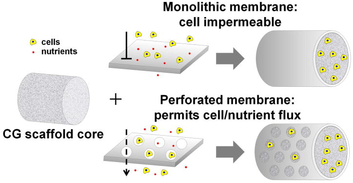
Schematic of core-shell composite design concept: integrating solid or perforated CG membranes with the anisotropic CG scaffold core.
MATERIALS AND METHODS
All reagents were purchased from Sigma-Aldrich (St. Louis, MO) unless otherwise specified.
CG suspension preparation
CG suspensions were prepared as previously described in detail.8,10,23 Briefly, type I microfibrillar collagen from bovine tendon and chondroitin sulfate derived from shark cartilage were mixed together at a 11.25:1 mass ratio and homogenized in 0.05 M acetic acid at 4°C to prevent collagen gelatinization. Suspensions with collagen content of 1 and 1.5 w/v% were created. 1.5% suspension was used to fabricate CG scaffolds while 1% suspension was used to synthesize CG membranes.
Fabrication of monolithic and perforated CG membranes
Monolithic CG membranes were fabricated by air-drying degassed CG suspension loaded in Petri dishes (75 mm diameter).9 Perforated membranes were created by evaporating CG suspension in molds containing arrays of polydimethylsiloxane (PDMS, MG Chemicals, Canada) microposts. PDMS micropost arrays were fabricated by layering PDMS (monomer: curing agent ratio 5:1) in a 3″ diameter polytetrafluoroethylene (PTFE) mold that contained 0.5 mm holes spaced 2.80 or 1.98 mm apart (corresponding to pore fractions of 2.5 and 5% respectively). Vacuum was pulled to degas the PDMS and promote infiltration into the holes. PDMS was cured at 37°C overnight, cut out of the PTFE mold, and then adhered to a Petri dish using fresh PDMS. Indentation studies were performed with 240 μm thick monolithic membranes that were fabricated by sequential addition of 150 mL 1% CG suspension as previously described.9 For all other experiments, 25 mL of 1% CG suspension was added to each dish to make 45 μm thick membranes.9
Fabrication of aligned CG scaffolds and scaffold-membrane composites via freeze-drying
CG scaffolds with aligned tracks of elongated pores were fabricated using a directional solidification method as previously described.8,9 Briefly, degassed CG suspension was added to thermally-mismatched molds consisting of a PTFE body and copper bottom. The more conductive copper promoted directional freezing in the scaffold longitudinal plane, resulting in the formation of geometrically anisotropic pores in that plane. Scaffolds were frozen at −10°C for 2 h and then sublimated at 0°C and 200 mTorr, resulting in dry, macroporous scaffolds that have previously been shown to support tenocyte adhesion, proliferation, alignment, and phenotypic stability.8,9,12 CG scaffold-membrane composites were fabricated by cutting pre-fabricated dry membranes and placing them directly into wells of the PTFE-copper freeze-drying mold.9 CG suspension was then pipetted into the CG membrane-loaded wells and allowed to hydrate the membrane for 15 min to promote integration. CG scaffold-membrane composites were then freeze-dried at −10°C as already described.
CG scaffold and membrane hydration and crosslinking
CG scaffolds, membranes, and scaffold-membrane composites first underwent physical cross-linking via dehydrothermal treatment in a vacuum oven (Welch, Niles, IL) at 105°C for 24 h.10 CG materials were then sterilized in ethanol for 1 h, rinsed repeatedly in phosphate-buffered saline (PBS), and then stored in PBS overnight at 4°C. Following hydration, CG materials underwent chemical crosslinking using carbodiimide chemistry as previously described15,24 in a solution of 1-ethyl-3-[3-dimethylaminopropyl] carbodiimide hydrochloride (EDC) and N-hydroxysulfosuccinimide (NHS) for 1.5 h at room temperature under shaking. Crosslinking for all experiments except for indentation studies was performed at a molar ratio of 5:2:1 EDC:NHS:COOH where COOH represents the molar amount of collagen (carboxyl) content. Indentation studies were conducted with membranes that underwent no crosslinking, carbodiimide crosslinking with an increased amount of NHS previously shown to improve protein immobilization efficiency (5:20.7:1),25 or standard carbodiimide crosslinking (5:2:1).
Mechanical analyses of crosslinked CG membranes
Indentation of hydrated membranes was performed in distilled water with an Instron 5500 series load frame (Instron, Canton, MA) in displacement control using a 3.95 mm diameter stainless steel spherical tip and a ramp-hold relaxation profile.26,27 The testing profile consisted of a 5 s ramp to an indentation depth of 100 μm followed by a 60 s hold during which stress relaxation was assessed and constitutive poroelastic parameters (shear moduli, hydraulic permeability, and intrinsic permeability) were calculated using previously described approaches.28,29 Approximate compressive elastic moduli were calculated (for comparison with tensile data) using the peak load occurring at the end of the 5 s ramp period, using the Hertzian elastic contact formula30 assuming a Poisson’s ratio of ν = 0.5 for hydrated materials at short times. Five tests were performed per 2 × 2 cm specimen (total of two specimens per group); tests were performed in the center region of each membrane, with a minimum 5 mm separation between membrane edge and any other indent (far in excess of the indenter contact radius of 0.45 mm). Indents were performed on fully-hydrated membranes (hydrated thickness ~ 1.5 mm).31
SEM analysis
The microarchitecture of the CG membranes and CG scaffold-membrane composites was qualitatively assessed using scanning electron microscopy (SEM) on a JEOL JSM-6060LV Low Vacuum Scanning Electron Microscope (JEOL USA, Peabody, MA). CG materials were imaged using both secondary and backscatter electron detection at low vacuum to avoid conductive coatings that may occlude microstructural features.32
CG material tensile mechanical testing
Hydrated, crosslinked CG membranes (6 mm width, 0.6 mm thickness, 10 mm gauge length) as well as CG scaffolds and scaffold-membrane composites (6 mm diameter, 15 mm gauge length) underwent tensile mechanical testing in an MTS Insight electromechanical load frame. Samples were held in place with rubberized grips to prevent slip.9 Materials were strained at a rate of 1 mm min−1 until failure. Elastic modulus was calculated as the slope of the linear elastic region of the stress-strain curve while yield strength (and corresponding yield strain) were determined from the stress and strain values at the end of the linear elastic region of the stress-strain curve.9,33
Tenocyte isolation and culture
Primary equine tenocytes were isolated from superficial digital flexor tendons of non-tendinopathic horses in a manner approved by the University of Illinois IACUC as previously described in great detail.34 Tenocytes were cultured in high glucose Dulbecco’s modified Eagle’s medium (DMEM) supplemented with 10% fetal bovine serum (FBS, Invitrogen, Carlsbad, CA) and antibiotics (Invitrogen) in normoxic conditions at 37°C/5% CO2 and used at passage 4 for all experiments.
CG membrane culture conditions
45 μm thick membranes were cut into 1″ diameter pieces for tenocyte culture experiments. Tenocytes were diluted to 5 × 10⁴, 1 × 10⁵, or 2 × 10⁵ cells per 400 μL media. Membranes were set in ultra-low attachment 6-well plates (Corning Life Sciences, Lowell, MA) and seeded with 400 μL of cell suspension. Tenocytes were allowed to attach for 3 h, after which 4 mL of culture media was added to cover the membranes. Media was switched out at days 2 and 5 of the 7 day experiment.
Tenocyte chemotaxis assay
Tenocyte chemotaxis into anisotropic CG scaffolds through CG membranes was evaluated using a modified Transwell membrane setup.8,25 Transwell membrane inserts (6.5 mm diameter) were purchased from Fisher Scientific (Pittsburgh, PA). The Transwell membranes were cut out from the inserts with a scalpel and replaced with 8 mm diameter punches of non-perforated (monolithic) or periodically perforated CG membranes (45 μm membrane thickness) adhered with a thin layer of PDMS. Modified inserts were sterilized via ethanol treatment before use. Hydrated, crosslinked CG scaffolds were placed in the bottom of 24-well plates, and were cut to enable direct contact between the scaffold and the CG membrane-modified Transwell insert.25 Tenocytes were seeded in the top compartment, and migration through the membrane into the scaffold was evaluated 24 h after cell seeding.25 For some groups, rat platelet-derived growth factor BB (PDGF-BB, R&D Systems, Minneapolis, MN) was added at a concentration of 100 ng mL−1 to the bottom compartment of the Transwell setup to examine whether the perforated membrane facilitated chemotaxis-based cell migration into the scaffold.8,25
Tenocyte metabolic activity quantification
Metabolic activity of tenocytes seeded on membranes or within scaffolds was evaluated using the alamarBlue® assay.35 Scaffolds and membranes were incubated in alamarBlue® dye solution for 3 h (scaffolds) or 5 h (membranes) at 37°C under gentle shaking. Live, viable cells continuously reduce the dye to a fluorescent product (resorufin) whose fluorescence was read on a standard microplate reader (540/580 nm excitation/emission, Tecan, Switzerland). All results were interpolated on a standard curve created with a known number of tenocytes and normalized to the original number of tenocytes seeded.
Tenocyte number quantification
Tenocyte number within CG scaffolds was determined by quantifying DNA via Hoechst 33258 labeling.36 Briefly, scaffold pieces were rinsed in PBS to remove dead or unattached cells and then digested in a papain solution at 60°C for 24 h. Fluorescence was read on a standard microplate reader (360/465 nm excitation/emission, Tecan, Switzerland). All results were interpolated on a standard curve created with a known number of tenocytes and normalized to the original number of tenocytes seeded.
Tenocyte culture in CG scaffold-membrane composites
The ability of CG scaffold-membrane composites to support tenocyte viability was assessed over 7 days of culture. Briefly, CG composites (6 mm diameter, 10 mm length) were placed in ultra-low attachment 6-well plates and seeded with 6 × 10⁵ total tenocytes. 1.5 × 10⁵ tenocytes were seeded on the open ends of the composite with the remaining cells seeded along the membrane-covered length of the composite. Tenocytes were allowed to attach for 3 h before additional cell culture media was added. For post-experimental evaluation of tenocyte activity within the scaffold core, the membrane shell was removed from each composite via forceps.
Immunofluorescence and confocal microscopy
Following 7 days of culture, membrane shells were removed with the CG scaffold cores subsequently fixed in 10% neutral buffered formalin and stored at 4°C until staining. Fixed tenocytes on the scaffolds were permeabilized in 0.1% Triton X100 in PBS for 15 min and then blocked in 3% BSA-PBS for at least 1 h. Scaffolds were then stained to visualize either the actin cytoskeleton or the expression of hypoxia-inducible factor 1α (HIF-1α). F-actin was stained with Alexa Fluor® 488 phalloidin (Invitrogen) for 30 min with Hoechst 33258 counterstaining of the nuclei. HIF-1α was visualized by incubation with a primary antibody (Abcam, Cambridge, MA, 1:100 dilution) for 6 h at room temperature followed by labeling with an AlexaFluor® 568 goat anti-rabbit secondary antibody (Invitrogen, 1:1000 dilution) for 1 h. HIF-1α-stained scaffolds were also counterstained with Hoechst 33258. Stained scaffolds were stored in the dark at 4°C until imaging. Confocal imaging was performed on a Zeiss LSM 710 multiphoton confocal microscope (10× objective) equipped with a Spectraphysics Mai-Tai Ti-Sapphire laser.
Statistical analysis
One-way analysis of variance (ANOVA) was performed on all data sets followed by Tukey-HSD post-hoc tests, except for CG membrane tenocyte culture where two-way ANOVA was used (independent variables: culture time, tenocyte seeding density). All analyses were performed in Excel. Significance was set at p < 0.05. CG membrane indentation studies used n = 2 membrane pieces per group (5 tests per membrane). CG membrane tenocyte culture used n = 3 membranes per group. Tensile mechanical tests used n = 8 CG scaffolds or scaffold-membrane composites per group. Chemotaxis experiments used n = 6 scaffolds per group. Tenocyte cultures in scaffold-membrane composites used at least n = 6 samples per group. Error is reported in figures as the standard error of the mean unless otherwise noted.
RESULTS AND DISCUSSION
CG membrane characterization
Membrane tensile modulus as well as constitutive poroelastic parameters (equilibrium shear modulus, hydraulic permeability, and intrinsic permeability) indicated a significant effect of CG crosslinking ratio and fiber organization on mechanical properties (Table 1). Results indicate that CG membrane equilibrium shear modulus, compressive elastic modulus, and tensile elastic modulus all increase with EDC crosslinking ratio (non-crosslinked, 5:20.7:1, 5:2:1 EDC:NHS:COOH ratio, Table 1). As expected, intrinsic and hydraulic permeability decrease with increased crosslinking ratio, with observed hydraulic permeability of the CG membranes being of similar magnitude to previously reported values for dense ECM such as small intestine submucosa (SIS),37 but were several orders of magnitude lower than those previously observed for significantly more porous CG scaffolds (scaffold porosity: 0.994; membrane porosity: 0.20–0.25).9,38 Hertzian elastic analysis of indentation tests on the CG membrane indicate a transverse compressive modulus of 354–1370 kPa, an order of magnitude below the in-plane tensile modulus (5–10 MPa) determined from macroscopic tensile tests (Table 1). This tension-compression nonlinearity is consistent with previous observations for soft biological tissues due to effects of fiber entanglements,39 and will be the subject of future investigation regarding mechanical behavior of CG membranes. While the 5:2:1 EDC crosslinked membranes were used for the remainder of this study, future efforts may leverage the 5:20.7:1 crosslinking ratio to create CG membranes as we have recently demonstrated this ratio allows more efficient immobilization of proteins such as growth factors to CG biomaterials.25
Table 1.
Membrane physical properties. CG membranes are nearly an order of magnitude stiffer in tension than compression. Indentation analyses indicate CG membranes, while displaying lower fluid mobility than CG scaffolds, are comparable to other naturally derived ECM constructs such as cartilage and SIS.37,38,40 Error is reported as standard deviation.
| Carbodiimide crosslinking ratio | |||
|---|---|---|---|
| Physical property | No crosslinking | 5:20.7:1 | 5:2:1 |
| Equilibrium shear modulus, kPa | 164 ± 52 | 448 ± 59* | 508 ± 46** |
| E (compressive), kPa | 354 ± 110 | 821 ± 86* | 1370 ± 120** |
| E (tensile), MPa | 4.07 ± 0.33 | 8.60 ± 1.26 * | 10.1 ± 1.16 ** |
| Hydraulic permeability, m4/N·s (measured) | 2.43 ± 1.0 × 10⁻¹⁴ | 1.26 ± 0.14 × 10⁻¹⁴* | 3.05 ± 0.37 × 10⁻¹⁵** |
| Intrinsic permeability, m2 (calculated; μwater = 0.9 mPa·s) | 2.19 ± 0.89 × 10⁻¹⁷ | 1.13 ± 0.12 × 10⁻¹⁷* | 2.75 ± 0.33 × 10⁻¹⁸** |
: significantly different compared to non-crosslinked membranes.
: significantly different compared to 5:20.7:1 crosslinking ratio.
Interestingly, the membranes exhibited significant poroviscoelastic behavior and dramatic relaxation in small time-frames. As such, the relaxation curve between 20 and 60 s was fit to a poroelastic model in order to obtain the results described here (Table 1). While the expected time-scale for cell-matrix interactions is expected to be primarily in the range dominated by the membrane poroelastic properties (> 20 s), ongoing efforts are exploring the viscoelastic and poroviscoelastic28 properties of the CG membranes.
Tenocyte culture on CG membranes
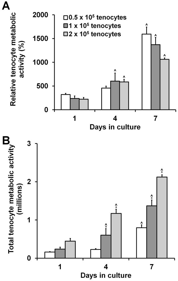
We next assessed the capacity of CG membranes to support tenocyte attachment and proliferation. CG membranes are biochemically identical to 3D scaffolds, making them potentially appealing as 2D substrates to easily and efficiently screen culture conditions without some of the inherent difficulties involved in working with 3D materials. CG membranes supported robust tenocyte attachment and metabolic activity with all three seeding densities (0.5, 1, and 2 × 10⁵ cells/membrane) resulting in more than 10 times higher metabolic activity than the activity of the originally seeded cells after 7 days in culture (Figure 2(a)). Tenocyte metabolic activity significantly increased in each group at each successive time point except for the 0.5 × 10⁵-seeded tenocyte group at day 4 (Figure 2(b)).
Figure 2.
Tenocyte adhesion and growth on CG membranes (n = 3). A) CG membranes support sustained mitochondrial metabolic activity and B) proliferation over 7 days in culture when seeded at 0.5 × 10⁵, 1 × 10⁵, or 2 × 10⁵ cells per membrane (1″ diameter pieces, 45 μm thick). *: significantly higher at that time point compared to next lowest seeding density. ^: significant increase compared to previous time point. Error bars indicate standard error of the mean.
Creation of perforated CG membranes
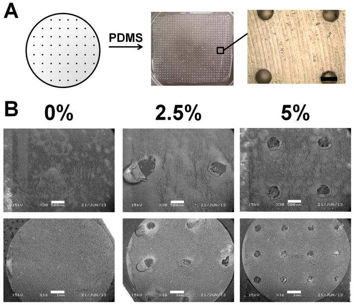
We next demonstrated an approach to create CG membranes with ordered microscale perforations as a precursor to a composite CG scaffold-membrane construct that was both mechanically robust and yet amenable to extrinsic cell migration. PTFE molds with a series of drilled holes were used as a negative template to create PDMS substrates containing arrays of microposts (Figure 3(a)). We found a high monomer: crosslink ratio (5:1) was required to reproducibly fabricate PDMS microposts that withstood both removal from the PTFE mold and buckling during the CG suspension evaporation process. Micropost integrity was maintained throughout the mold and membrane fabrication processes with few posts collapsing. Moreover, CG membranes displayed final perforation dimensions (~500 μm diameter) consistent with the size of the posts (500 μm diameter, Figure 3(b)). Here we reported results for membranes with pores covering either 2.5 or 5% of the total membrane surface area (Figure 3). While possible to create PDMS micropost arrays at higher perforation fractions (e.g., 10%), we found it difficult to reproducibly fabricate and successfully remove such membranes from the micropost arrays (data not shown).
Figure 3.
Perforated CG membrane fabrication paradigm. A) Teflon molds (0.5 mm diameter holes) were used to create PDMS micropost arrays with 2.5% or 5% (shown in figure) post coverage. Scale bar: 500 μm. B) SEM images of perforated membranes demonstrates the creation of holes in the 2.5% and 5% versions, while no holes are visible in the non-perforated (monolithic, 0%) membrane. Scale bars: 500 μm (top row), 1 mm (bottom row).
Tenocyte migration through membranes into CG scaffolds
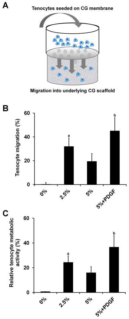
Extrinsic cells are critical to the tendon wound healing process.22 Therefore, we assessed the capability of our CG membranes (both monolithic and perforated groups) to support cell migration through the membrane using a modified Transwell setup, where the Transwell membrane was replaced with a non-perforated or perforated (2.5%, 5%) CG membrane. The CG membrane was brought in contact with a CG scaffold in the lower chamber (with or without exogenous PDGF added to the media), with the cell suspension added above the membrane in the upper chamber. Total cell infiltration into the scaffold was then evaluated after 24 h. Monolithic (non-perforated) membranes supported negligible tenocyte migration into CG scaffolds. Perforated membrane groups permitted robust tenocyte recruitment with the 2.5% perforated and 5% perforated + PDGF groups supporting significantly greater tenocyte chemotaxis into the CG scaffold than the monolithic (0%) group (p < 0.03) (Figure 4). Consistent with previous results in the literature,8,25 PDGF-BB supplementation supported the highest levels of tenocyte recruitment. Interestingly, the non-supplemented 2.5% group had increased tenocyte chemotaxis versus the non-supplemented 5% group, although this difference was not significant (p = 0.27). Since the perforations in the CG membranes are much larger than normal Transwell membrane pores (500 μm versus 0.5–8 μm), initial leakage of the cell suspension from the top chamber into the media surrounding the CG scaffold in the lower chamber (especially in the 5% group) may account for the reduced tenocyte migration and attachment to the underlying scaffold in the 5% group versus the 2.5% membrane. Despite these issues, all perforated membrane groups supported increased cell penetration into the scaffold relative to non-perforated membranes.
Figure 4.
Tenocyte recruitment through membrane into CG scaffolds (n = 6). Tenocytes are not able to penetrate non-perforated membranes while robust cell migration into the underlying CG scaffold is observed in all perforated groups. A) Schematic of modified Transwell setup, B) Number of migrated tenocytes, C) Migrated tenocyte relative metabolic activity. a: significantly greater than 0% group. b: significantly greater than 0% and 5% groups. Error bars indicate standard error of the mean.
Fabrication and mechanical characterization of CG scaffold-membrane composites
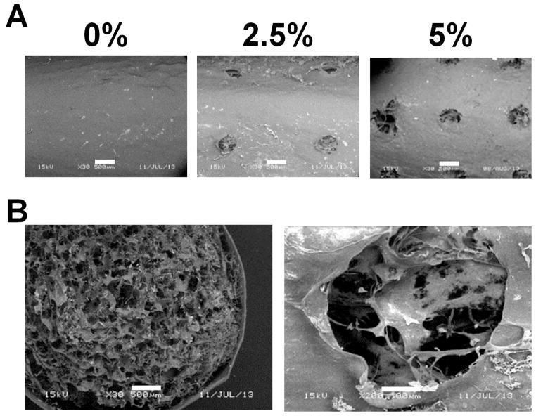
We subsequently fabricated CG scaffold-membrane composites with an increasing degree of membrane perforation (0, 2.5%, 5% perforations; Figure 5). Notably, the porous microstructure of the scaffold core was clearly visible through the perforations of the membrane shell, suggesting good integration (Figure 5). Coupled with previous evidence that CG scaffold-membrane composites remained stable post-fabrication,9 these results suggest significant scaffold-membrane composite integration.
Figure 5.
Microstructure of perforated CG scaffold-membrane composites. A) SEM images of outer membrane shells. While the scaffold core is not visible through the monolithic (0%) membrane it is clearly visible in the perforated (2.5% and 5%) groups. B) Membranes show good integration with the scaffold core. Scale bars: 500 μm, 100 μm (second picture in part B).
We next evaluated the mechanical properties of the perforated membrane-scaffold composites. Previous work with non-perforated membranes showed that incorporation of the membrane shell could increase the composite elastic modulus in a manner predictable by layered composites theory.9 However, the scaffold core for those composites had a relative density of 0.5%. Scaffolds with this low density have subsequently been shown to be susceptible to significant tenocyte-mediated contraction, resulting in a loss of pore anisotropy and more importantly, down-regulation of characteristic tenogenic genes.12 In contrast, higher density scaffolds (relative density of 1.5%) were shown to resist contraction, maintain an open pore network, and promote elevated and sustained expression of tenogenic markers.12 Therefore, for this investigation we created a series of composites with a 1.5% relative density scaffold core and membrane shells of a single thickness (45 μm)9 but varying perforation density (0, 2.5, and 5%). We compared the mechanical properties of these core-shell composites with 1.5% relative density scaffolds. While we occasionally observed minor delamination of the shell from the core in the non-perforated membrane group, we saw improved integration in the 2.5 and 5% groups. This may be due to increased contact area between the scaffold core and membrane shell during initial hydration, freeze-drying, and crosslinking.
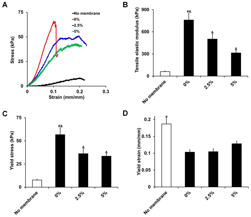
Representative stress-strain curves indicated that CG scaffolds and scaffold-membrane composites behaved like open cell porous foams when loaded in tension, displaying characteristic toe, linear elastic, and plastic deformation regimes15 (Figure 6(a)). All three scaffold-membrane composites tested displayed significantly greater tensile elastic moduli (p = 0.01, Figure 6(b)) and yield strength (p = 0.004, Figure 6(c)) as well as significantly lower yield strain (p = 0.004, Figure 6(d)) compared to scaffolds without membrane shells. However, the perforated composites had significantly lower tensile elastic moduli and yield stress compared to the non-perforated composite (p < 0.02) with no difference observed in yield strain (p > 0.05). Although the 5% perforated composite had a significantly lower tensile elastic modulus than the 2.5% perforated composite (p = 0.04), there was no significant difference in yield stress between the two groups (p = 0.63). This is due to the 5% perforated composite having a higher yield strain value. Not surprisingly, there was a tradeoff observed between increased perforation density (corresponding to hypothesized increases in permeability and cellular activity) and mechanical integrity of the composite, although all composites were significantly stronger than the scaffolds alone. This tradeoff as well as optimization of constructs for in vivo tensile loading will be explored more extensively in ongoing studies to optimize all parameters involved.
Figure 6.
CG scaffold and scaffold-membrane composite mechanical properties (n = 8). A) Characteristic stress-strain curves, B) tensile elastic modulus, C) yield stress, and D) yield strain. While perforated composites display significantly higher tensile elastic moduli and yield stress compared to scaffolds alone, they are not as strong as monolithic, non-perforated composites. #: significantly greater than all other experimental groups, &: significantly greater than no membrane group. Error bars indicate standard error of the mean.
Tenocyte culture in CG scaffold-membrane composites
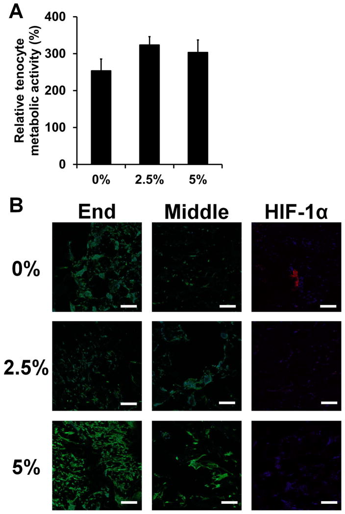
Finally, we examined the capability of CG scaffold-membrane composites to support sustained tenocyte bioactivity and cellular distribution throughout the entire material. All groups were able to support sustained tenocyte metabolic activity (Figure 7(a)). Not surprisingly, confocal imaging of tenocyte distribution within the composite scaffold revealed robust cellularity at the open ends of the scaffold for all groups (Figure 7(b)). However, the perforated membrane groups displayed improved cellular distribution along the length of the scaffold core (covered by the membrane shell). Importantly, the expression of HIF-1α in the middle of the constructs was observed in the non-perforated group only (Figure 7(b)). These data highlight the inherent difficulties of not only promoting adequate cellular distribution in large tissue engineering constructs, but also maintaining adequate permeability to promote nutrient diffusion and prevent hypoxia. Fabricating core-shell composites with well-ordered perforations permissive to cellular and biomolecular flux may offer a pathway towards these goals.
Figure 7.
Tenocyte bioactivity in CG scaffold-membrane composites (n = 6). A) Relative tenocyte metabolic activity within composite core after 7 days of culture. B) Representative confocal micrographs showing cellular distribution and hypoxia-inducible factor 1α (HIF-1α; images taken from middle region) expression within composite cores. All groups show strong cellularity at the open ends of the composites while the perforated composite groups (2.5, 5%) display increased cellular infiltration and reduced HIF-1α expression compared to the monolithic composite group (0%) along the length of the scaffold. Green channel: AlexaFluor® 488 (phalloidin), Blue channel: Hoechst 33258 (nuclei), Red channel: AlexaFluor® 568 (HIF-1α). Scale bars: 200 μm. Error bars indicate standard error of the mean.
A limitation of the analyses described here is the necessity of removing the membrane shell in order to isolate the contribution of cells within the scaffold core for subsequent assays. Consistent with qualitative observations of sporadic core-shell delamination during handling, it was much easier to remove the membrane shells from the non-perforated membrane group compared to the perforated groups. This may have influenced the results of the metabolic activity and confocal imaging studies. However, it is important to note that this improved integration for the perforated membrane groups, while complicating the in vitro studies here, would be an advantage for subsequent in vivo models. Ongoing efforts are exploring suture retention within these membranes in order to facilitate in vivo repair trials. Additionally, we can envision an alternative repair strategy where the membrane shell would be wrapped around the scaffold core during surgery instead of being integrated directly. We also anticipate that CG membranes, both monolithic and perforated, could be useful for a range of in vitro studies as 2D substrates presenting natural ligands for cell bioactivity while permitting more straightforward analysis of cell behavior readouts than 3D CG scaffolds.
CONCLUSIONS
Mechanically efficient materials are needed for orthopedic tissue engineering that can simultaneously support discrete cellular activities while withstanding physiological loads. Building on a previously developed CG core-shell composite for tendon tissue engineering, this work characterized the poroelastic behavior of CG membranes and demonstrated that they could support tenocyte viability as 2D cell culture substrates with identical biochemical makeup to 3D CG scaffolds. Next, we demonstrated that CG membranes containing well-ordered arrays of microscale pores could facilitate cell migration through the membrane into an underlying CG scaffold, a design parameter that is likely to be critical for the in vivo success of these composites. We were able to form CG scaffold-perforated membrane composites that showed good core-shell integration and significantly improved mechanical properties compared to naked scaffolds, although mechanics were reduced compared to monolithic, non-perforated composites. Finally, we showed that large CG composites (6 mm diameter, 10 mm length) containing a perforated membrane could support sustained tenocyte metabolic activity as well as improved cellular distribution and reduced HIF-1α expression compared to a non-perforated membrane variant. Ongoing work is assessing the suitability of these composites for in vivo tendon repair.
Acknowledgments
The authors would like to acknowledge Dr. Allison Stewart (Veterinary Sciences, UIUC) for providing equine tenocytes, Dr. Hyunjoon Kong (ChBE, UIUC) for generously sharing mechanical testing equipment, Dr. Sandra McMasters (SCS, UIUC) for preparation of culture media, Mr. Manuel Ramirez for assistance with membrane fabrication and cell culture, and the SCS Machine Shop for fabrication of membrane molds. This material is based upon work supported by the National Science Foundation under Grant No. 1105300. Research reported in this publication was supported by the National Institute of Arthritis and Musculoskeletal and Skin Diseases of the National Institutes of Health under Award Numbers R21 AR063331 and R03 AR062811. The content is solely the responsibility of the authors and does not necessarily represent the official views of the National Institutes of Health. Laura Mozdzen was funded at UIUC from National Science Foundation (NSF) Grant 0965918 IGERT: Training the Next Generation of Researchers in Cellular and Molecular Mechanics and BioNanotechnology. Oliver Armitage is funded by the EPSRC (UK). We are grateful for additional funding for this study provided by the Chemistry-Biology Interface Training Program NIH NIGMS T32GM070421 (SRC), the Chemical and Biomolecular Engineering Dept. (BAH), and the Institute for Genomic Biology (BAH) at the University of Illinois at Urbana-Champaign.
References
- 1.Butler DL, Juncosa-Melvin N, Boivin GP, Galloway MT, Shearn JT, Gooch C, Awad H. Functional tissue engineering for tendon repair: A multidisciplinary strategy using mesenchymal stem cells, bioscaffolds, and mechanical stimulation. J Orthop Res. 2008;26(1):1–9. doi: 10.1002/jor.20456. [DOI] [PubMed] [Google Scholar]
- 2.Galatz LM, Ball CM, Teefey SA, Middleton WD, Yamaguchi K. The outcome and repair integrity of completely arthroscopically repaired large and massive rotator cuff tears. J Bone Joint Surg Am. 2004;86-A(2):219–24. doi: 10.2106/00004623-200402000-00002. [DOI] [PubMed] [Google Scholar]
- 3.Altman GH, Horan RL, Lu HH, Moreau J, Martin I, Richmond JC, Kaplan DL. Silk matrix for tissue engineered anterior cruciate ligaments. Biomaterials. 2002;23(20):4131–41. doi: 10.1016/s0142-9612(02)00156-4. [DOI] [PubMed] [Google Scholar]
- 4.Cooper JA, Jr, Sahota JS, Gorum WJ, 2nd, Carter J, Doty SB, Laurencin CT. Biomimetic tissue-engineered anterior cruciate ligament replacement. Proc Natl Acad Sci U S A. 2007;104(9):3049–54. doi: 10.1073/pnas.0608837104. [DOI] [PMC free article] [PubMed] [Google Scholar]
- 5.Moffat KL, Kwei AS, Spalazzi JP, Doty SB, Levine WN, Lu HH. Novel nanofiber-based scaffold for rotator cuff repair and augmentation. Tissue Eng Part A. 2009;15(1):115–126. doi: 10.1089/ten.tea.2008.0014. [DOI] [PMC free article] [PubMed] [Google Scholar]
- 6.Kjaer M, Langberg H, Heinemeier K, Bayer ML, Hansen M, Holm L, Doessing S, Kongsgaard M, Krogsgaard MR, Magnusson SP. From mechanical loading to collagen synthesis, structural changes and function in human tendon. Scandinavian Journal of Medicine & Science in Sports. 2009;19(4):500–510. doi: 10.1111/j.1600-0838.2009.00986.x. [DOI] [PubMed] [Google Scholar]
- 7.Screen HRC, Seto J, Krauss S, Boesecke P, Gupta HS. Extrafibrillar diffusion and intrafibrillar swelling at the nanoscale are associated with stress relaxation in the soft collagenous matrix tissue of tendons. Soft Matter. 2011;7(23):11243–11251. [Google Scholar]
- 8.Caliari SR, Harley BAC. The effect of anisotropic collagen-GAG scaffolds and growth factor supplementation on tendon cell recruitment, alignment, and metabolic activity. Biomaterials. 2011;32(23):5330–5340. doi: 10.1016/j.biomaterials.2011.04.021. [DOI] [PMC free article] [PubMed] [Google Scholar]
- 9.Caliari SR, Ramirez MA, Harley BAC. The development of collagen-GAG scaffold-membrane composites for tendon tissue engineering. Biomaterials. 2011;32(34):8990–8998. doi: 10.1016/j.biomaterials.2011.08.035. [DOI] [PMC free article] [PubMed] [Google Scholar]
- 10.Yannas IV, Lee E, Orgill DP, Skrabut EM, Murphy GF. Synthesis and characterization of a model extracellular matrix that induces partial regeneration of adult mammalian skin. Proc Natl Acad Sci USA. 1989;86(3):933–937. doi: 10.1073/pnas.86.3.933. [DOI] [PMC free article] [PubMed] [Google Scholar]
- 11.Harley BA, Spilker MH, Wu JW, Asano K, Hsu HP, Spector M, Yannas IV. Optimal degradation rate for collagen chambers used for regeneration of peripheral nerves over long gaps. Cells Tissues Organs. 2004;176(1–3):153–65. doi: 10.1159/000075035. [DOI] [PubMed] [Google Scholar]
- 12.Caliari SR, Weisgerber DW, Ramirez MA, Kelkhoff DO, Harley BAC. The influence of collagen-glycosaminoglycan scaffold relative density and microstructural anisotropy on tenocyte bioactivity and transcriptomic stability. J Mech Behav Biomed Mater. 2012;11:27–40. doi: 10.1016/j.jmbbm.2011.12.004. [DOI] [PMC free article] [PubMed] [Google Scholar]
- 13.Harley BAC, Gibson LJ. In vivo and in vitro applications of collagen-GAG scaffolds. Chem Eng J. 2008;137(1):102–121. [Google Scholar]
- 14.Yannas IV, Burke JF, Gordon PL, Huang C, Rubenstein RH. Design of an artificial skin. II. Control of chemical composition. J Biomed Mater Res. 1980;14(2):107–32. doi: 10.1002/jbm.820140203. [DOI] [PubMed] [Google Scholar]
- 15.Harley BA, Leung JH, Silva EC, Gibson LJ. Mechanical characterization of collagen-glycosaminoglycan scaffolds. Acta Biomater. 2007;3(4):463–74. doi: 10.1016/j.actbio.2006.12.009. [DOI] [PubMed] [Google Scholar]
- 16.Ho ST, Hutmacher DW, Ekaputra AK, Hitendra D, Hui JH. The evaluation of a biphasic osteochondral implant coupled with an electrospun membrane in a large animal model. Tissue Eng Part A. 2010;16(4):1123–41. doi: 10.1089/ten.TEA.2009.0471. [DOI] [PubMed] [Google Scholar]
- 17.Violas P, Abid A, Darodes P, Galinier P, de Gauzy KS, Cahuzac JP. Integra artificial skin in the management of severe tissue defects, including bone exposure, in injured children. Journal of Pediatric Orthopaedics-Part B. 2005;14(5):381–384. doi: 10.1097/01202412-200509000-00013. [DOI] [PubMed] [Google Scholar]
- 18.Xu L, Cao D, Liu W, Zhou G, Zhang WJ, Cao Y. In vivo engineering of a functional tendon sheath in a hen model. Biomaterials. 2010;31(14):3894–902. doi: 10.1016/j.biomaterials.2010.01.106. [DOI] [PubMed] [Google Scholar]
- 19.Chen YJ, Chung MC, Jane Yao CC, Huang CH, Chang HH, Jeng JH, Young TH. The effects of acellular amniotic membrane matrix on osteogenic differentiation and ERK1/2 signaling in human dental apical papilla cells. Biomaterials. 2012;33(2):455–63. doi: 10.1016/j.biomaterials.2011.09.065. [DOI] [PubMed] [Google Scholar]
- 20.Guda T, Walker JA, Singleton BM, Hernandez JW, Son JS, Kim SG, Oh DS, Appleford MR, Ong JL, Wenke JC. Guided bone regeneration in long-bone defects with a structural hydroxyapatite graft and collagen membrane. Tissue Eng Part A. 2013;19(17–18):1879–88. doi: 10.1089/ten.tea.2012.0057. [DOI] [PMC free article] [PubMed] [Google Scholar]
- 21.Harley BA, Hastings AZ, Yannas IV, Sannino A. Fabricating tubular scaffolds with a radial pore size gradient by a spinning technique. Biomaterials. 2006;27(6):866–874. doi: 10.1016/j.biomaterials.2005.07.012. [DOI] [PubMed] [Google Scholar]
- 22.Kinneberg KRC, Galloway MT, Butler DL, Shearn JT. The native cell population does not contribute to central-third graft healing at 6, 12, or 26 weeks in the rabbit patellar tendon. Journal of Orthopaedic Research. 2013;31(4):638–644. doi: 10.1002/jor.22261. [DOI] [PMC free article] [PubMed] [Google Scholar]
- 23.O’Brien FJ, Harley BA, Yannas IV, Gibson L. Influence of freezing rate on pore structure in freeze-dried collagen-GAG scaffolds. Biomaterials. 2004;25(6):1077–86. doi: 10.1016/s0142-9612(03)00630-6. [DOI] [PubMed] [Google Scholar]
- 24.Olde Damink LH, Dijkstra PJ, van Luyn MJ, van Wachem PB, Nieuwenhuis P, Feijen J. Cross-linking of dermal sheep collagen using a water-soluble carbodiimide. Biomaterials. 1996;17(8):765–73. doi: 10.1016/0142-9612(96)81413-x. [DOI] [PubMed] [Google Scholar]
- 25.Caliari SR, Harley BA. Composite Growth Factor Supplementation Strategies to Enhance Tenocyte Bioactivity in Aligned Collagen-GAG Scaffolds. Tissue Eng Part A. 2013;19(9–10):1100–12. doi: 10.1089/ten.tea.2012.0497. [DOI] [PMC free article] [PubMed] [Google Scholar]
- 26.Strange DG, Oyen ML. Composite hydrogels for nucleus pulposus tissue engineering. J Mech Behav Biomed Mater. 2012;11:16–26. doi: 10.1016/j.jmbbm.2011.10.003. [DOI] [PubMed] [Google Scholar]
- 27.Galli M, Comley KSC, Shean TAV, Oyen ML. Viscoelastic and poroelastic mechanical characterization of hydrated gels. Journal of Materials Research. 2009;24(3):973–979. [Google Scholar]
- 28.Strange DGT, Fletcher TL, Tonsomboon K, Brawn H, Zhao XH, Oyen ML. Separating poroviscoelastic deformation mechanisms in hydrogels. Applied Physics Letters. 2013;102(3) [Google Scholar]
- 29.Galli M, Oyen ML. Fast Identification of Poroelastic Parameters from Indentation Tests. Cmes-Computer Modeling in Engineering & Sciences. 2009;48(3):241–269. [Google Scholar]
- 30.Johnson KL. Contact Mechanics. Cambridge University Press; 1985. [Google Scholar]
- 31.Harley BA, Lynn AK, Wissner-Gross Z, Bonfield W, Yannas IV, Gibson LJ. Design of a multiphase osteochondral scaffold III: Fabrication of layered scaffolds with continuous interfaces. J Biomed Mater Res A. 2010;92(3):1078–93. doi: 10.1002/jbm.a.32387. [DOI] [PubMed] [Google Scholar]
- 32.Gibson LJ, Ashby MF, Harley BA. Cellular materials in nature and medicine. Cambridge, U.K: Cambridge University Press; 2010. [Google Scholar]
- 33.Kapoor A, Caporali EH, Kenis PJ, Stewart MC. Microtopographically patterned surfaces promote the alignment of tenocytes and extracellular collagen. Acta Biomater. 2010;6(7):2580–9. doi: 10.1016/j.actbio.2009.12.047. [DOI] [PubMed] [Google Scholar]
- 34.Tierney CM, Jaasma MJ, O’Brien FJ. Osteoblast activity on collagen-GAG scaffolds is affected by collagen and GAG concentrations. J Biomed Mater Res A. 2009;91(1):92–101. doi: 10.1002/jbm.a.32207. [DOI] [PubMed] [Google Scholar]
- 35.Kim YJ, Sah RL, Doong JY, Grodzinsky AJ. Fluorometric assay of DNA in cartilage explants using Hoechst 33258. Anal Biochem. 1988;174(1):168–76. doi: 10.1016/0003-2697(88)90532-5. [DOI] [PubMed] [Google Scholar]
- 36.Beatty MW, Ojha AK, Cook JL, Alberts LR, Mahanna GK, Iwasaki LR, Nickel JC. Small intestinal submucosa versus salt-extracted polyglycolic acid-poly-L-lactic acid: a comparison of neocartilage formed in two scaffold materials. Tissue Eng. 2002;8(6):955–968. doi: 10.1089/107632702320934056. [DOI] [PubMed] [Google Scholar]
- 37.O’Brien FJ, Harley BA, Waller MA, Yannas IV, Gibson LJ, Prendergast PJ. The effect of pore size on permeability and cell attachment in collagen scaffolds for tissue engineering. Technol Health Care. 2007;15(1):3–17. [PubMed] [Google Scholar]
- 38.Ramanujan S, Pluen A, McKee TD, Brown EB, Boucher Y, Jain RK. Diffusion and convection in collagen gels: implications for transport in the tumor interstitium. Biophys J. 2002;83(3):1650–1660. doi: 10.1016/S0006-3495(02)73933-7. [DOI] [PMC free article] [PubMed] [Google Scholar]
- 39.Huang CY, Soltz MA, Kopacz M, Mow VC, Ateshian GA. Experimental verification of the roles of intrinsic matrix viscoelasticity and tension-compression nonlinearity in the biphasic response of cartilage. Journal of Biomechanical Engineering-Transactions of the Asme. 2003;125(1):84–93. doi: 10.1115/1.1531656. [DOI] [PubMed] [Google Scholar]


