Abstract
Objective
The applicability of the edge chipping method to denture tooth materials was assessed. These are softer materials than those usually tested by edge chipping. The edge chipping fracture resistances of polymethylmethacrylate (PMMA) based and two filled resin composite denture tooth materials were compared.
Methods
An edge chipping machine was used to chip rectangular blocks and flattened anterior denture teeth. Force versus edge distance data were collected over a broad range of forces and distances. Between 20 and 65 chips were made per condition depending upon the material, the scatter, and the indenter type. Different indenter types were used including Rockwell C, sharp conical 120°, Knoop, and Vickers. The edge toughness, Te, was evaluated for different indenter types.
Results
The edge chipping data collected on the blocks matched the data collected from flattened teeth. High scatter, particularly at large distances and loads, meant that many tests (up to 64) were necessary to compare the denture tooth materials and to ascertain the appropriate data trends. A linear force – distance trend analysis was adequate for comparing these materials. A power law trend might be more appropriate, but the large scatter obscured the definitive determination of the precise trend. Different indenters produce different linear trends, with the ranking of: sharp conical 120°, Rockwell C, and Knoop, from lowest to highest edge toughness. Vickers indenter data were extremely scattered and a sensible trend could not be obtained. Edge toughness was inversely correlated to hardness.
Significance
Edge chipping data collected either from simple laboratory scale test blocks or from actual denture teeth may be used to evaluate denture materials. The edge chipping method’s applicability has been extended to another class of restorative materials.
Introduction
The edge chipping test is used to evaluate the resistance of brittle materials to flaking near an edge as shown in Figure 1. This method, originally developed in the late 1980s to study hard metal cutting tools at the National Physical Laboratory in London, [1–4] has been applied to dental restoration materials [5–13] and been to human dentin [14] and enamel [15]. A short review paper on edge chipping as applied to dental materials was recently prepared [10]. A detailed evaluation of six computer aided design and machining) CAD/CAM restorative materials including porcelains glass ceramics, filled resin composites, and zirconia was recently reported [16].
Figure 1.
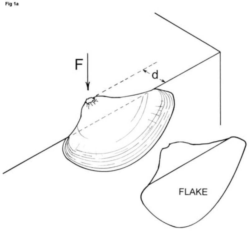
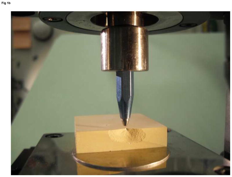
Edge chipping. The image on the right shows a sharp conical indenter that has made a large chip in a 4 cm wide slab of dental stone which is easy to photograph. Actual chips are much smaller.
Chips are formed by advancing an indenter or stylus into a material near an edge. The force required for chip formation is recorded as a function of the distance from the edge. The greater the load application point distance is from the edge, the greater is the force that is needed to create the chip. The shape of the chip is usually independent of the material tested.
In this work, the edge chipping test was applied to denture tooth materials. They are not as hard and are more compliant (lower elastic modulus) than some of the materials cited above and exhibit some ductility. Nevertheless, clinical chipping of denture teeth had been observed, and a simple quick test to evaluate candidate materials for dentures would be helpful. The goal of this work was to: ascertain whether the laboratory chipping tests could compare the edge chipping resistance of candidate denture materials and expand the applicability of the test method to softer materials.
Three hypotheses are set forth in this paper: edge chip indenter type does not affect test results, force versus distance data follow a linear trend; and the edge chip resistance of several denture tooth materials can be differentiated.
Materials and Methods
Three resin based denture tooth materials were evaluated as shown in Table 1.a The first is a highly cross-linked polymethylmethacrylate (PMMA) with organic filler [17]. It was available in the form of monolithic wear block type rectangular blocks and also anterior teeth that were made of three layers. The upper two layers were incisal and dentin designated versions of the highly cross-linked PMMA, which had the similar composition and properties, but different pigmentation. A supporting cervical (neck) region was a less highly cross-linked PMMA.
Table 1.
Materials tested#
| Material | Primary constituents† | Elastic Modulus (GPa) * | HV0.5/30 (MPa) | Fracture toughness, KIc (MN/m1.5) *** |
|---|---|---|---|---|
| PMMA Blueline SR Vivodent Plus DCL |
Dimethacrylate 8% PMMA 71–73% cross-linked prepolymer 20% |
3.4 | 200 | 1.2 (0.02) |
| Composite I SR Phonares NHC |
Aliphatic-aromatic UDMA 17%–25% PMMA 19% – 24% inorganic filler 18% –25%, silanized silica inorganic filled prepolymer (PMMA/UDMA) 35% – 40% |
4.5 | > 260 | - |
| Composite II SR Phonares II Incisal and Dentin |
MMA 17–20% Dimethacrlyates (UDMA) 17.5 –22% PMMA 6–9% inorganic filler 9–12%, silanized silica inorganic filled prepolymer (PMMA/UDMA) 39–45% |
3.9 incisal 4.4 dentin |
235 Incisal 258 dentin |
1.40 (0.15) incisal 1.55 (0.10) dentin |
Manufacturer data [17].
Vickers hardness, 0.5 kgf (4.9 N) force, 30 seconds dwell.
Single edge V-notched beam, 3 point bending. Computed from maximum force.
PMMA, polymethylmethacrylate; UDMA, urethandimethacrylate; NHC, nanohybrid composite
The other two materials are hybrid silica-filled urethandimethacrylate (UDMA) composites [17]. They have small differences in composition and filler content. Composite I (SR Phonares NHC) was available in the form of wear blocks and four-layered anterior denture teeth. It is described by the manufacturer as a “nano hybrid composite” (NHC) [17]. The two uppermost (incisal and dentin) layers, into which the chips were made, were supported by cervical (neck) material that was a low cross-linked PMMA. Composite I had been developed to offer reduced shrinkage and improved wear resistance and durability in comparison to acrylic teeth [17], but there were some reports of in vivo chipping fractures. Composite II (SR Phonares II) was a newer refined composite, with slight changes in the composition as compared to Composite I, and was designed to mitigate or eliminate the reported in vivo chipping fractures. The dentin and incisal versions of Composites I and II differ only in the amount of pigments added.
Test pieces for all three materials were available in the form of six wear test type rectangular blocks, nominally 10 mm × 15 mm × 4.5 mm thick. The six surfaces were polished to make well-defined, reproducible edges. They were progressively hand ground wet with a rotary polishing wheel using 1200, 2400, and 4000 grit wet SiC papers.
Incisal denture teeth of all three materials were also prepared by polishing as shown in Figure 2a. The gingival side was ground flat to support the tooth evenly on the edge chipping machine base as shown in Figure 2b. The incisal surface was ground parallel to the base. Finally the palatal surface was ground flat to eliminate a small amount of material and to make the 90° edge. The incisal and palatal surfaces were polished to provide a single well defined 90° edge.
Figure 2.
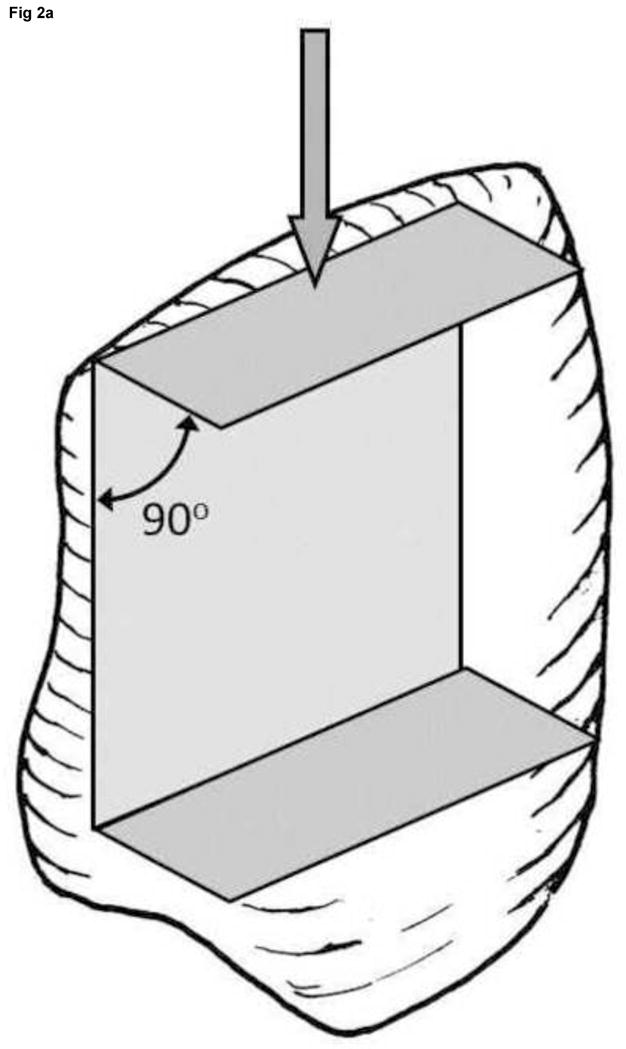
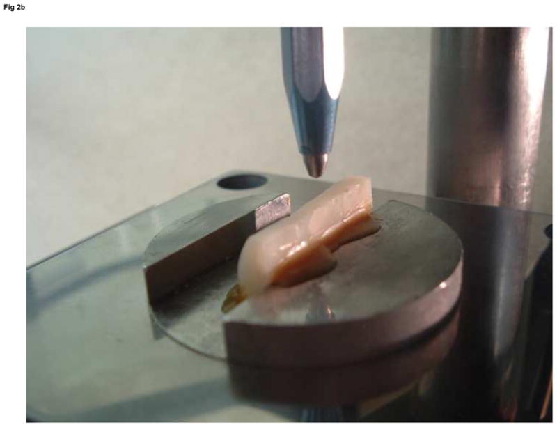
The incisal, gingival and lingual sides were ground flat and polished to provide a 90 degree edge as shown in (a) for chipping in the direction of the arrow. (b) shows three teeth waxed side-by-side on the mounting plate for chipping.
A commercial edge chipping machine (Engineering Systems Model CK 10, Nottingham, UK) was used to make the chips. All test pieces were waxed to a mounting plate. At the beginning of a test sequence, the indenter was positioned over a flat portion of the specimen well away from the edge, and a small indentation was made. The instrument crosshair was then precisely lined up with the center of the indentation. The X-Y stage then was moved to make indentations and chips at prescribed distances from the edge, ranging from 0.05 mm to 0.60 mm. Force was gradually applied in displacement control until the chip fractured off the specimen. The forces increased linearly during the loading sequence with the exception that a slight hesitation of a few seconds occurred at about 35 N – 45 N as the mass of the machine head (about 3 kg) shifted on the drive screws. It was thought that the loading rate may be important, so the maximum machine speed of 3 mm/min was used for most experiments although some were done at 1 mm/min. The chipping sequence took 5 s to 30 s depending upon the material and edge distance. Temperatures were 20° C to 25° C. The peak load was recorded. Twenty to thirty-five chips were typically made per material. A sharp conical 120° single crystal diamond indenter was used as described previously [10,16]. For comparison, some experiments were also done with Rockwell C, and Knoop indenters. Only a few experiments were done with a Vickers indenter, since results were highly variable and chips often did not form. The long axis of the Knoop indenter, or one edge axis of the Vickers indenter, was aligned parallel to the test piece edge.
One problem detected in this work, was “overchipping.” Ideally, once a chip pops off, the indenter should instantly extract. In practice, the indenter continued to contact the intact side of the test piece for a split second prior to indenter extraction and made additional damage and a larger indentation. We verified this by interrupting some chips just prior to their popping off and comparing the indentation size and chip sizes to those where the chip did pop off. This overchipping behavior severely affected measurements of the edge distances by post-test examination. The distances sometimes were overestimated. Even the commercial edge chipping machine that we used was susceptible to this problem. It had a sensitive break detection circuitry that automatically extracted the indenter once a sudden load drop off was detected. The sensitivity could be adjusted, but in many cases some overchipping still occurred. The matter was worse in compliant materials. When a full chip formed, it might not pop completely off and would only partially detach.b In this study, edge distances were precisely set prior to each test in order to avoid interpretation problems of the contact site for measurement of the edge distance.
A further problem with the softer, more compliant materials was that sometimes the chips did not actually detach from the test piece side. In such cases, the side of the test piece was visually observed with a hand magnifier during the test, and once the customary large chip popped in suddenly, the test was stopped manually and the peak force recorded. In a number of instances, depending upon the material and the type of indenter and the loading rate, a chip did not form and the indenter started pushing into the material creating substantial plastic deformation. These tests were stopped and the trial deemed invalid.
Edge chipping force versus distance data trends are either linear or fit a power law as discussed in detail in ref [16]. If the data fit a linear trend,
| (1) |
where F is the chipping force and d is the distance from the edge, the usual convention is to report the slope of the fitted line as the edge toughness, Te, (N/mm).c Edge chip resistance may be correlated to fracture toughness for many materials as discussed elsewhere. Although there are cases (e.g., refs. 4 and 10) where a power law might fit the data better, nearly all the data in this study were well fit by the linear trend. Watts et al.[13,14] defined an edge strength, SE(0.5) with units of N, which denotes the force necessary to create a chip at the distance of 0.5 mm,. This is felt to be a clinically relevant distance.d If the data follow a linear trend, equation 1, it is readily apparent that the numerical value of the edge strength, SE(0.5) is exactly one half the value of the edge toughness, Te. They have different units, however: N for the former and N/mm for the latter.
Edge chips were photographed with a stereoptical microscopee at magnifications up to 63 power to the eyes. Chips sometimes were stained with a green felt tip marker pen in order to cut down internal reflections and to highlight topographical and fractographic features.
Hardness tests were conducted with the sharp conical 120°, Rockwell C, and Knoop indenters mounted on the edge chipping machine, which is designed to do hardness tests as well as the edge chipping. For the sharp conical and Rockwell C indenters, the peak load was set to 100 N with a 15 s dwell time. A peak load of 19.6 N and dwell time of 15 s was used for the Knoop indentations. It was easy to measure the diameter of the large round indentations using a stereoptical microscope with a X-Y traversing stage with a 1 micrometer resolution, provided that care was taken to illuminate the indentations the same way each time. For all three indenters, hardness was computed as the load divided by the projected surface area. This is the conventional procedure for Knoop indentations, but is new for the cases of the Rockwell C and sharp conical indenters. Five to fifteen indentations were made in each case.
Results
The results are presented by material type in Table 2 and in the following figures. Figure 3 shows the force to make chips in the PMMA followed a linear trend. The smallest scatter was obtained with the sharp conical 120° indenter, which required the least force to make chips. Only eighteen of thirty-two trials on the wear blocks and twelve of 18 trials on six teeth were successful. Some tests were interrupted when chips did not pop off and deformations became excessive. The data collected on teeth overlapped the data collected on wear blocks as shown by the solid and dashed lines in the figure. The Knoop indenter required about 35% more force to make chips than for the sharp conical 120° indenter. Thirty-two successful outcomes were obtained from thirty-three trials. The scatter increased dramatically at larger distance. Less success was obtained with the Rockwell C indenter. Eighteen trials were attempted, but only seven generated chips and the scatter was extreme. In most experiments, material was pushed off the side without chip formation.
Table 2.
Edge chip results†
| Material | Test piece | IndenterX | N XX | Edge Toughness Te, slope of linear eq.1 (N/mm) | Edge strength SE(0.5) (N) calculated* | Hardness (GPa) |
|---|---|---|---|---|---|---|
|
| ||||||
| PMMA SR Vivodent Plus DCL |
Wear block | 120° SC | 18 | 475 (44) | 238 | 0.337 (0.014) |
| Knoop | 32 | 642 (108) | 321 | 0.225 (0.005) | ||
| Rockwell C | 7 | (535 ⊗) | - | 0.326 (0.007) | ||
|
| ||||||
| Mounted and flattened teeth | 120° SC | 13 | 500 (120) | 250 | - | |
|
| ||||||
| Combined wear block and teeth | 120° SC | 31 | 486 (51) | 243 | ||
|
| ||||||
| Composite I SR Phonares NHC |
Wear block | 120° SC | 25 | 249 (38) | 125 | 0.459 (0.009) |
| Vickers | 8 | (575 ⊗) | - | - | ||
| Knoop | 32 | 554 (63) | 277 | 0.302 (0.025) | ||
| Rockwell C | 17 | 412 (35) | 206 | 0.448 (0.009) | ||
|
| ||||||
| Mounted and flattened teeth | 120° SC | 15 | 251 (23) | 126 | - | |
|
| ||||||
| Combined wear block and teeth | 120° SC | 40 | 250 (22) | 125 | ||
|
| ||||||
| Composite II SR Phonares II |
Wear block-incisal | 120° SC | 26 | 470 (83) | 235 | 0.395 (0.007) |
| Knoop | 33 | 705 (60) | 358 | 0.280 (0.013) | ||
| Rockwell C | 16 | 587 (99) | 294 | 0.405 (0.006) | ||
|
| ||||||
| Wear block-dentin | 120° SC | 33 | 450 (61) | 225 | 0.380 (0.008) | |
| Vickers | 9 | (1600 ⊗) | - | - | ||
| Knoop | 31 | 596 (55) | 298 | 0.267 (0.018) | ||
| Rockwell C | 14 | 490 (69) | 245 | 0.395 (0.001) | ||
|
| ||||||
| Mounted and flattened teeth | 120° SC | 11 | 472 (311) | 236 | - | |
|
| ||||||
| Combined wear block and teeth | 120° SC | 70 | 462 (48) | 231 | - | |
| Knoop | 64 | 651 (47) | 326 | - | ||
| Rockwell C | 30 | 545 (63) | 273 | - | ||
Uncertainties, if available, are in parenthesis and are ± one standard deviation
SC denotes sharp conical
N is the number of chips
eq. 1 with d = 0.5 mm
Data was very inconsistent. Most trials did not result in a chip.
Figure 3.
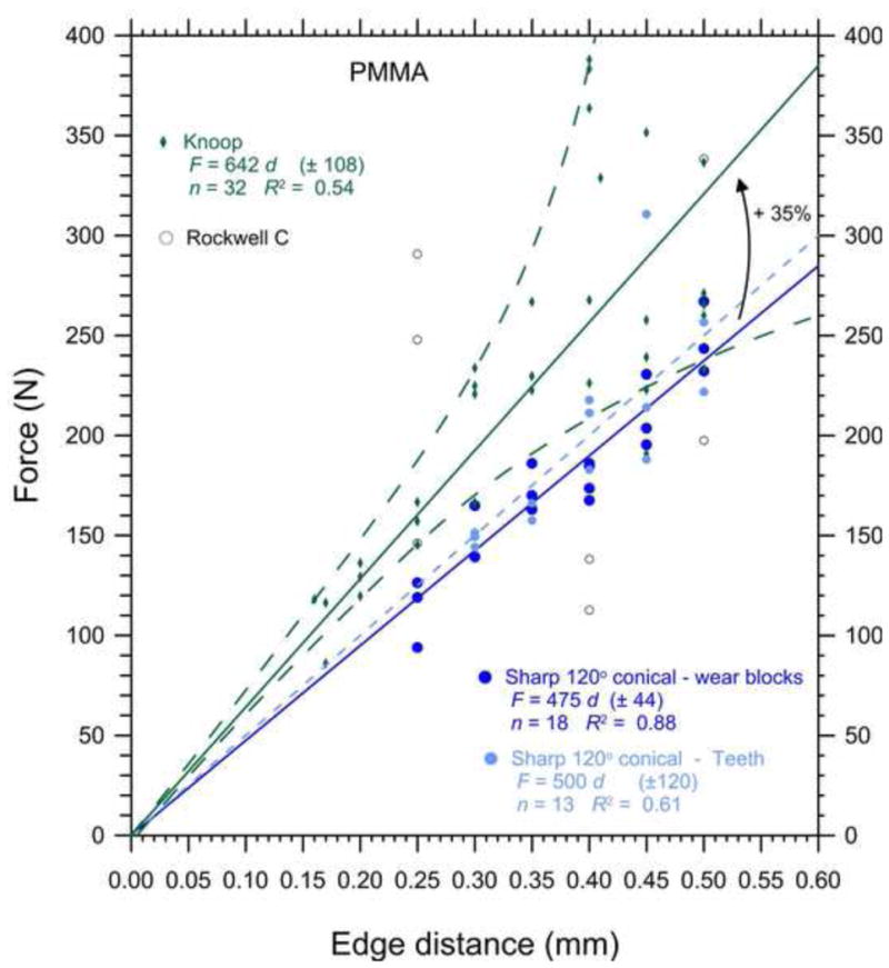
Edge chip results for the PMMA. The sharp conical indenter results for the wear blocks (solid blue line) and teeth (short dashed blue line) overlapped The Knoop indenter data spread (shown by the long dashed lines that flare out) increased dramatically with greater distances. The Knoop edge toughness, Te, was 35% greater than the sharp conical edge toughness, Te.
Figure 4 illustrates the type of chips formed in the PMMA. Indentation sizes were quite large. During a loading sequence, the sides of the test pieces could even be observed bulging slightly. Hoop stress splitting cracks might pop in as shown in Figure 4, and eventually the major chip fragment would pop off. Sometimes the chip popped off suddenly, and in other cases, it formed suddenly, but stayed attached to the side. There was insufficient stored elastic energy to drive the crack all the way through to the surface. The sharp conical indenter 120° produced the most reliable data trend, although only eighteen of thirty-two trials were successful. Deformation was even more extensive with the Rockwell C indenter which also had a 120° angle, but a much blunter tip (radius of 0.2 mm). The Knoop indenter tended to push into the material, like a chisel, and a chip would be pried off the side. The automatic break detection circuitry of the testing machine did not always detect the sudden pop in of the final crack, so the chipping process in these experiments was manually observed with a hand magnifier on the illuminated, polished specimen side surface. Once the chip popped to its final shape, the machine was manually stopped and the peak force recorded.
Figure 4.

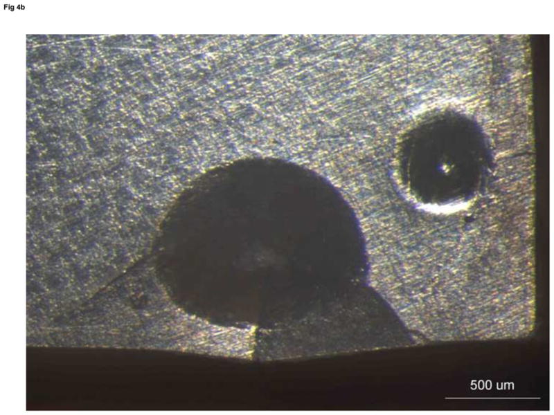
Chip formation for softer materials. (a) is a schematic. (b) is a top view of a chip in the PMMA with very large indentations formed by a Rockwell C indenter.
Figure 5 shows the results for Composite I, which chipped much more readily and at lower forces than the PMMA. The sharp conical indenter data from teeth very closely matched and overlapped the data from wear blocks. Figure 6 shows some of the chips and the large indentation deformations. Twenty-five of thirty-seven trials formed valid chips in the wear blocks and fifteen of nineteen in the teeth. All thirty-two Knoop and seventeen of eighteen Rockwell C trials were successful. Chips usually popped off with an audible snap. During a test, the specimen side typically bulged outwards a small amount prior to the chip popping off. Despite large deformation zones, the data trend for the Rockwell C indenter had the same or less scatter (smaller standard deviation and greater R2 correlation coefficient) as for the sharp conical and Knoop indenters. The Vickers experiments were more problematic and only eight of fifteen worked and it was necessary to manually detect the chip pop off. Deformations were excessive in many of the unsuccessful trials.
Figure 5.
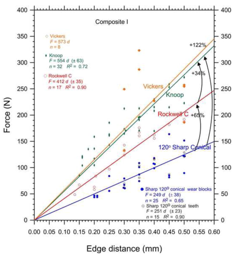
Composite I edge chip results. The sharp conical data for the wear blocks and teeth overlap. Only a few highly variable outcomes were obtained with the Vickers indenter. The arced lines with arrows show the percent differences of the edge toughness as measured by the different indenters.
Figure 6.
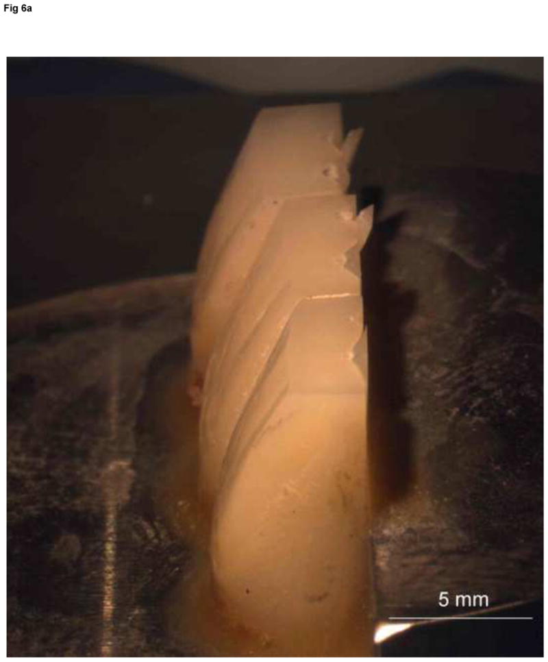
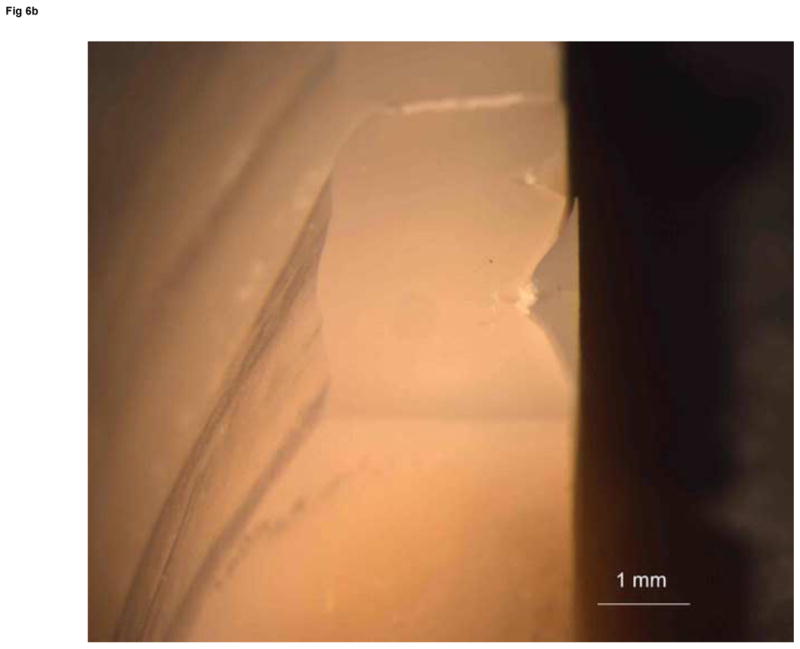
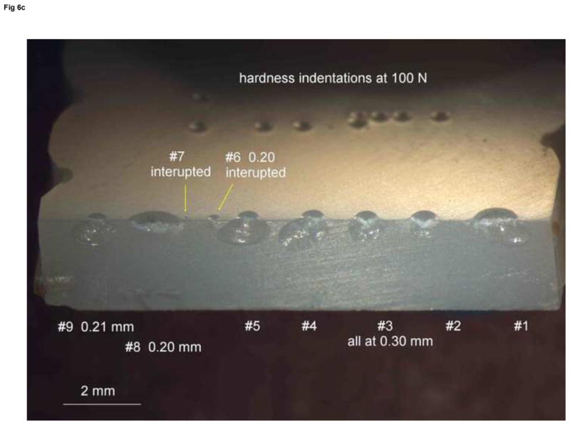
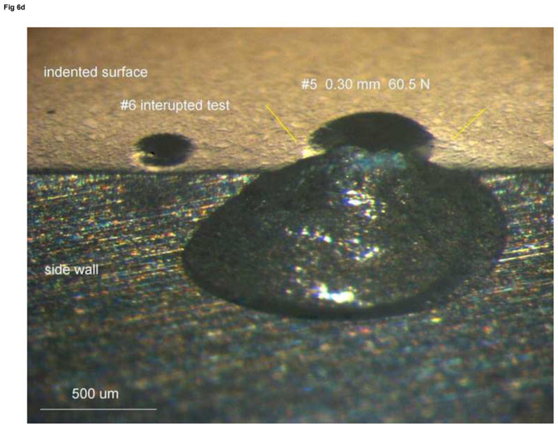
Edge chips in Composite I. (a) and (b) show sharp conical indenter chips in Composite I teeth. (c) and (d) show sharp conical chips on a wear block.
Figure 7 shows the sharp conical 120° chip results for Composite II. There is substantial scatter, but the outcomes from the wear block tests on the incisal and dentin versions of the material are statistically indistinguishable from the teeth outcomes. Figure 8 shows the combined sharp conical data compared to results from the Knoop and Rockwell C indenters. Twelve experiments were done with the Vickers indenter and the results were wildly variable. Chips often did not form. In cases where they did, forces from 300 N to almost 1000 N were needed. A Vickers trend line could not be obtained. The same indenter trend hierarchy was observed as with Composite I: sharp conical required the least force, Knoop the greatest, and Rockwell C in between. Supplemental Figure 1 in the on-line version of this paper shows representative chips and some of their large deformations.
Figure 7.
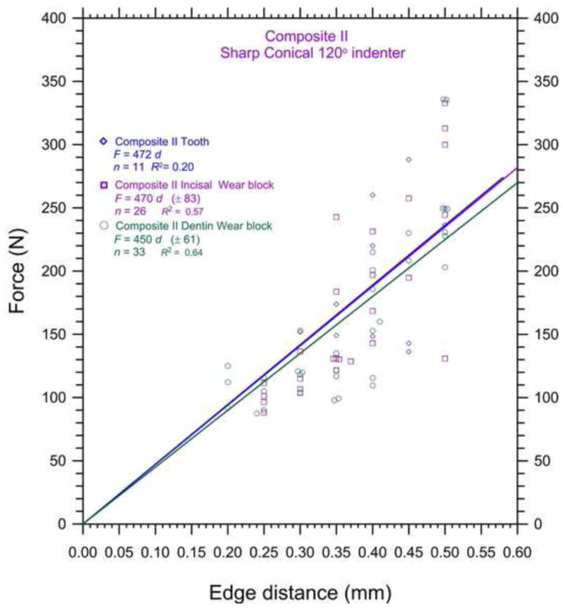
Sharp conical 120° edge chip results for Composite II. Despite the large scatter, the outcomes for the wear blocks and the tooth match. The edge toughness values, Te, are statistically indistinguishable.
Figure 8.
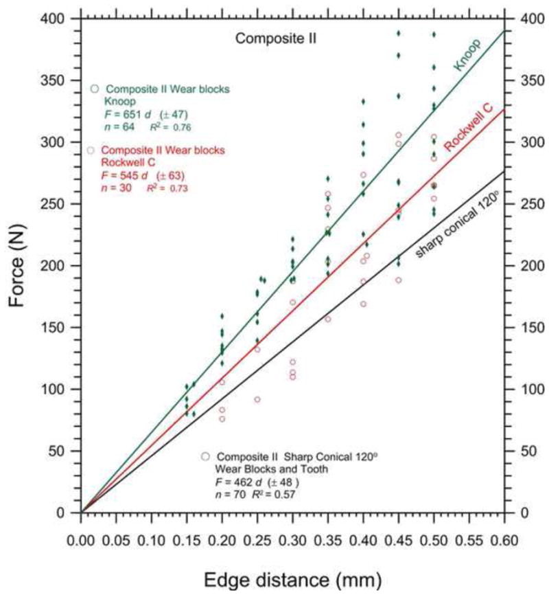
Edge chip results for Composite II. Sharp conical 120° data from figure 7 are combined and shown by a single fitted line without data points for clarity.
Large deformations were noted with all indenters, but the problems seemed worse with the Vickers indenter. A number of tests were done where the chipping test was interrupted at a set peak load, and indentation s and partial chips compared to indentation s formed in the interiors, well away from the edge. In many cases, the indentation size at the edge was much larger than for a comparable indentation in the interior, and the edge indentation s were often misshapen. Evidently once a chip formed, or material started to bulge outwards from an edge, the edge became more compliant. The indenter then “leaned” more the interior side and formed asymmetric indentation s. This action contributed to “overchipping.” In other words, in such compliant materials once a chip formed, indenter follow through created additional damage in the brief instant before the indenter extracted.
Discussion
The results showed that the edge chip resistance varied with material and with indenter type. Figure 10 shows the edge toughness, Te, for the three materials for the three indenters. Data for the incisal and dentin versions of Composite II are combined, because (as Table 2 shows) there were no statistically significant differences between them. For all three materials the data from teeth were combined with data for wear blocks, since there was no effect of specimen type. The Rockwell C outcome for the PMMA was about 535 N/mm, but with very high uncertainty due to great scatter, so it is shown with a question mark in the figure. All three indenters showed that the Composite I had the least chip resistance. The sharp conical 120° data was the most sensitive. All three indenter types indicated that the edge chip resistance of Composite II had been improved and indeed matched the original PMMA baseline material. Chipping experiments by other groups using different procedures have also shown that Composite II has improved edge chip resistance [17]. One procedure done by the manufacturer used a universal testing machine with an indenter to apply load directly onto anterior and posterior denture teeth cusps. Chipping forces were increased by factors of 1.8 times and 3.3 times, respectively. In another study (attributed to Watts and Silikas in ref 17), the edge strength, SE(0.5), was evaluated with a Vickers indenter in an edge chipping machine identical to the one in the present study. The crosshead rates were also 3 mm/min. Anterior denture teeth had their mesial and distal surfaces ground flat and the indenter loaded onto small portions of the incisal edges. Composite II had an edge strength 1.4 to 2.5 times greater than three other denture materials including one cross-linked PMMA.
Figure 10.
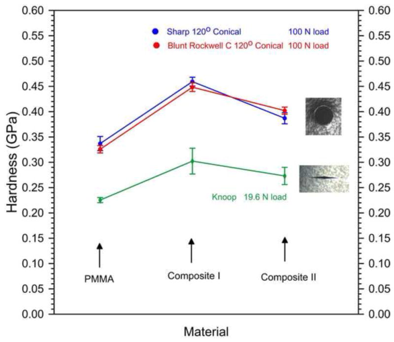
Hardness of the three materials as a function of indenter type. The sharp conical and Rockwell C data overlap.
Deformations were large in these soft materials. The chipping process was not as much a brittle process as with the materials evaluated in earlier studies mentioned in the introduction [1–10]. The deformations led to significant bulging of the side surfaces. Sometimes “membrane type” hoop initial splitting occurred prior to the main chip pop off. Morrell and Gant [4] observed the same behavior with Rockwell C chips in some tool steels, and when these were heat treated to soften them and increase plasticity, the edge could not be flaked. In many cases, chips did not form at all and the experiments had to be stopped due to excessive deformations. Their figures 6 and 7 are very similar to Figs. 4a, 6, and on-line supplemental figure 1 in the present work. Morrell and Gant conducted many tests (forty or more per material) in order to deal with the high scatter (as much as a factor of two in chipping force for a given distance). They concluded that linear F versus d trends were adequate despite the large scatter, but did show two data sets with nonlinear fits.
In the present work, the side splitting, the side bulging, and difficulty in making chips were a problem with the Vickers and Rockwell C indenters. Even the Knoop experiments, which had good data consistency, seemed to be more a matter of gouging off material like a chisel on wood. The sharp conical 120° indenter was convenient to use and produced a high fraction of valid tests. This indenter has a relatively sharp angle compared to Vickers and Knoop indenters, so it is not surprising that less force was needed to make a chip. The effect of indenter angle is addressed in another study [18] which shows that wedging forces account for the variation of edge chip results with indenter angle. With all indenters, once a chip popped off there was a split second delay before the testing machine extracted the indenter and this led to additional deformation and “overchipping.” Most of the experiments were done at the fastest machine displacement rate of 3 mm/min. A rate effect could not be discerned with the limited testing done at 1 mm/min. Testing at lower speeds was not done since deformations probably would have been even more extreme.
The large scatter made assessment of the correct F versus d trend difficult. The scatter was much greater than that observed for dental ceramic and glass ceramic materials [5,8,10,16] and may be due in large part to the greater deformations in the denture tooth materials. A couple of data sets showed possible power law trends, with rapidly increasing force at greater distances, but one set showed the opposite. There did not seem to be any advantage to using more complicated trend analyses, and the linear analysis seemed to produce a good numerical evaluation and ranking of the materials. The variability of results underscores the need to make many chips, however, since a few trials could be very misleading.
Edge chipping analyses usually try to correlate results with fracture toughness, or critical strain energy release rate. Fracture toughness data from the manufacturer (Table 1) showed that Composite II did have 11%–30% greater fracture resistance than a highly cross-linked PMMA. One distinctive correlation was detected in this study is shown in Figure 10. The material with the weakest edge chipping resistance had the highest hardness. Hence, it would appear that Composite I may have been developed to improve wear resistance and durability, but an accompanying increase in hardness and stiffness (elastic modulus) made it more brittle and susceptible to chipping in service. The problem appears to have been rectified by Composite II.
For illustrative purposes only, some denture teeth were chipped by a 5 mm ball directly contacting the incisal edges. This is shown in Supplemental Figure 2 in the on-line version of this paper. Although the chips that formed are illustrative of clinical fractures, it may be difficult to obtain a repeatable geometrical contact between the curved surfaces of the contoured tooth and the ball. Chips did form, but only after substantial deformation. Some quantitative Vickers indenter edge chip experiments directly onto incisal edges of anterior denture teeth and onto cusps of posterior denture teeth are described in ref. [17]. Future work could further explore the relationships between testing block shaped laboratory specimens and actual teeth.
One of the three hypotheses is refuted: edge chip indenter type does affect test results (but the trends are similar). The other two are confirmed; force versus distance data follow a linear trend (for all practical purposes); and the edge chip resistance of denture materials can be differentiated but only if a sufficient number of chips are performed due to the high scatter.
Conclusions
The edge chipping test method was successfully applied to three denture materials including a highly cross linked PMMA and two composite materials. The utility of the test method has been extended to softer materials than those previously tested. Edge toughness was inversely correlated with hardness.
Supplementary Material
Supplemental Figure 1. Composite II chips. (a) shows two unsuccessful trials with the Vickers indenter at d = 0.50 mm. Deformations are extreme. A chip can be seen about to come off the top surface (arrows), but the test was stopped when the forces almost reached the machine limit. (b) shows a sharp conical test that was interrupted just prior to the chip popping off. A membrane crack is apparent as well as the chip cracks. (c) shows a block tilted back with two sharp conical chips. (d) shows a block with two Rockwell C chips.
Supplemental Figure 2. Some denture teeth were directly loaded with a 5 mm diameter ceramic ball onto their original incisal surfaces (a). Chips did form as shown in (b), but usually with substantial deformation at the contact site.
Figure 9.
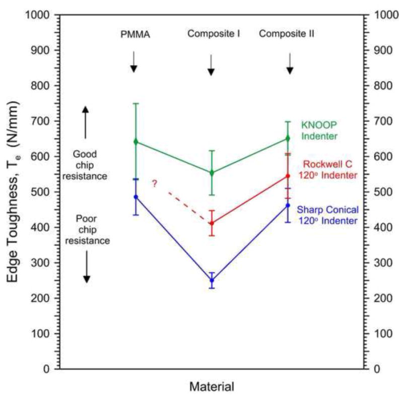
The edge toughness for the three materials as a function of indenter type.
Acknowledgments
This work was made possible by a grant from NIH, R01-DE17983, and the people and facilities at the National Institute of Standards and Technology and the ADAF Paffenbarger Research Center. The authors wish to thank Ivoclar, Schaan, Liechtenstein and Amherst, New York, USA for donating the materials for this study.
Footnotes
Commercial products and equipment are identified only to specify adequately experimental procedures and does not imply endorsement by the authors, institutions or organizations supporting this work, nor does it imply that they are necessarily the best for the purpose.
The problem was particularly difficult with some softer resin materials (not included in the present work). In such cases, we resorted to visual monitoring of the chip formation on the side of the specimen with the aid of a hand magnifier. The crosshead return button was manually activated as quickly as possible.
Edge toughness is sometimes denoted as M.
Watts et al. [11,12] did not use this specific symbol SE(0.5) in their publications, but it was agreed upon in private communication in April 2012.
Model M10, Leica/Wild Heerbrug, Switzerland.
Publisher's Disclaimer: This is a PDF file of an unedited manuscript that has been accepted for publication. As a service to our customers we are providing this early version of the manuscript. The manuscript will undergo copyediting, typesetting, and review of the resulting proof before it is published in its final citable form. Please note that during the production process errors may be discovered which could affect the content, and all legal disclaimers that apply to the journal pertain.
References
- 1.Almond EA, McCormick NJ. Constant-Geometry Edge-Flaking of Brittle Materials. Nature. 1986;1:53–55. [Google Scholar]
- 2.McCormick NJ, Almond EA. Edge Flaking of Brittle Materials. J Hard Mater. 1990;1(1):25–51. [Google Scholar]
- 3.McCormick NJ. Edge Flaking as a Measure of Material Performance. Metals and Materials. 1992;8:154–156. [Google Scholar]
- 4.Morrell R, Gant AJ. Edge Chipping of Hard Materials. Int J Refract Metals and Hard Mat. 2001;19:293–301. [Google Scholar]
- 5.Quinn JB, Su L, Flanders L, Lloyd IK. “Edge Toughness” and Material Properties Related to the Machining of Dental Ceramics. Mach Sci and Technol. 2000;4:291–304. [Google Scholar]
- 6.Quinn JB, Lloyd IK. Flake and Scratch Size Ratios in Ceramics. In: Varner JR, Quinn GD, editors. Fractography of Glasses and Ceramics IV, Ceramic Transactions. Vol. 122. The American Ceramic Society; Westerville, OH: 2001. pp. 55–72. [Google Scholar]
- 7.Quinn JB, Lloyd I, Katz RN, Quinn GD. Machinability: What Does it Mean? Ceram Eng Sci Proc. 2003;24(4):511–516. [Google Scholar]
- 8.Quinn JB, Sundar V, Parry EE, Quinn GD. Comparison of Edge Chipping Resistance of PFM and Veneered Zirconia Specimens. Dental Materials. 2010;26(1):13–20. doi: 10.1016/j.dental.2009.08.005. [DOI] [PMC free article] [PubMed] [Google Scholar]
- 9.Quinn JB, Quinn GD. Material Properties and Fractography of an Indirect Dental Resin Composite. Dental Materials. 2010;26(6):589–599. doi: 10.1016/j.dental.2010.02.008. [DOI] [PMC free article] [PubMed] [Google Scholar]
- 10.Quinn JB, Quinn GD, Hoffman KM. Edge Chip Fracture Resistance of Dental Materials. to be publ. Ceram Eng Sci Proc. 2012;33(2):71–84. [Google Scholar]
- 11.Watts DC, Issa M, Ibrahim A, Wakiga J, Al-Samadani K, Al-Azraqi M, Silikas N. Edge Strength of Resin-Composite Margins. Dental Materials. 2008;24:129–133. doi: 10.1016/j.dental.2007.04.006. [DOI] [PubMed] [Google Scholar]
- 12.Baroudi K, Silikas N, Watts DC. Edge-Strength of Flowable Resin-Composites. J Dentistry. 2008;36:63–68. doi: 10.1016/j.jdent.2007.10.006. [DOI] [PubMed] [Google Scholar]
- 13.Zhang Y, Chai H, Lee JJW, Lawn BR. Chipping Resistance of Graded Zirconia Ceramics for Dental Crowns. J Dent Res. 2012;3:311–315. doi: 10.1177/0022034511434356. [DOI] [PMC free article] [PubMed] [Google Scholar]
- 14.Whitbeck ER, Quinn GD, Quinn JB. Effect of Calcium Hydroxide on Dentin Fracture Resistance. J Res NIST. 2011;116(4):743–749. doi: 10.6028/jres.116.017. [DOI] [PMC free article] [PubMed] [Google Scholar]
- 15.Chai H, Lee JW, Lawn BR. On the Chipping and Splitting of Teeth. J Mech Beh Biomed Mater. 2011;4:315–321. doi: 10.1016/j.jmbbm.2010.10.011. [DOI] [PubMed] [Google Scholar]
- 16.Quinn GD, Giuseppetti AA, Hoffman KH. Chipping Fracture Resistance of Dental CAD/CAM Restorative Materials: Part 1. Procedures and Results, accepted by Dental Materials; Oct. 2013; [DOI] [PMC free article] [PubMed] [Google Scholar]
- 17.SR Phonares® II Scientific Documentation, Ivoclar, Schaan, Liechtenstein. 2012 Jun; www.ivoclarvivadent.com.
- 18.Quinn GD, Giuseppetti AA, Hoffman KH. Chipping Fracture Resistance of Dental CAD/CAM Restorative Materials: Part 2: Analysis of Indenter Wedging and Correlations with other Fracture Properties. 2013 subm. to Dental Materials. [Google Scholar]
Associated Data
This section collects any data citations, data availability statements, or supplementary materials included in this article.
Supplementary Materials
Supplemental Figure 1. Composite II chips. (a) shows two unsuccessful trials with the Vickers indenter at d = 0.50 mm. Deformations are extreme. A chip can be seen about to come off the top surface (arrows), but the test was stopped when the forces almost reached the machine limit. (b) shows a sharp conical test that was interrupted just prior to the chip popping off. A membrane crack is apparent as well as the chip cracks. (c) shows a block tilted back with two sharp conical chips. (d) shows a block with two Rockwell C chips.
Supplemental Figure 2. Some denture teeth were directly loaded with a 5 mm diameter ceramic ball onto their original incisal surfaces (a). Chips did form as shown in (b), but usually with substantial deformation at the contact site.


