Abstract
Finite element analysis is used to evaluate and design L-band surface loop resonators for in vivo electron paramagnetic resonance (EPR) tooth dosimetry. This approach appears to be practical and useful for the systematic examination and evaluation of resonator configurations to enhance the precision of dose estimates. The effects of loop positioning in the mouth are examined, and it is shown that the sensitivity to loop position along a row of molars is decreased as the loop is moved away from the teeth.
Keywords: accident analysis, dosimetry, electrons, magnetic fields
INTRODUCTION
Electron paramagnetic resonance (EPR) tooth dosimetry is being developed to allow retrospective assessments of individual exposures to ionizing radiation following events where it is suspected that large numbers of people could have been affected. EPR is the process by which unpaired electrons absorb microwave radiation in the presence of a static magnetic field. Ionizing radiation creates unpaired electrons, or free radicals, throughout the body. While most of these react rapidly and disappear in tissues such as teeth, bones, fingernails, toenails and hair, the unpaired electrons are persistent and can be used for dosimetry (Gordy et al. 1955; Brady et al. 1968). This project focuses on the in vivo measurement of the relative number of unpaired electrons in tooth enamel using EPR spectroscopy to estimate the dose of ionizing radiation, but the results should also be applicable to other resonators for in vivo measurements.
This paper uses finite element analysis (FEA) to characterize existing surface loop resonators (Salikhov et al. 2003; Walczak et al. 2005) and to optimize the detection loop for maximum dosimetric sensitivity. The potential advantage of this approach is that it enables the systematic examination of a range of structures so that many parameters can be effectively examined to facilitate development of more optimal configurations. It would be very time-consuming and inefficient to construct and physically test the many different resonators that would be required to examine all plausible configurations, but with simulation of the structures and calculated characterizations of their performances, such construction can be reserved to verify the predictions from the simulations and test the most promising designs.
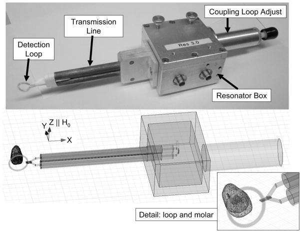
Considerable work has been done toward the development of in vivo EPR tooth dosimetry (Iwasaki et al. 2005a and b; Swartz et al. 2005, 2006, 2007; Williams et al. 2007). A static magnetic field, referred to as H0, is created with either a permanent magnet or an electromagnet that is typically oriented through the head from ear to ear. A surface loop resonator is shown in Fig. 1, which resonates at 1.2 GHz. The authors are interested primarily in the components of the RF magnetic field that are perpendicular to H0 because they are the components absorbed by the electrons, which give rise to the dosimetric EPR signal. It is assumed the magnetic field modulation is uniform across the sample and parallel to H0. Interactions between the modulation field and the resonator are not included in the simulation.
Fig. 1.
Top: A picture of an existing L-band resonator designed for tooth dosimetry (Walczak et al. 2005). The key components of the resonator are labeled. The detection loop is placed on the teeth and the transmission line connects the detection loop to inductively coupled loops in the resonator box. The coupling adjust knob is used to achieve the best coupling in the measurement environment. Bottom: A model used to simulate a resonator in HFSS. The direction of the static magnetic field, H0, is shown and is parallel to the Z-axis. The inset on the lower-right is a close-up of the loop and molar.
The goal of the research described in this paper is to investigate the effect of tooth vs. loop positioning for existing detection loops. The finite element model is presented; the parameters used to evaluate the performance of different resonators, loop configurations, and tooth/loop positioning are described; and the results of the various studies are presented.
FINITE ELEMENT MODEL
Ansoft Corporation’s High Frequency Structure Simulator (v11, HFSS) was used to solve the electromagnetic fields of the resonators considered here. As with the analytical solution, the numerical solution depends on the material properties and boundary conditions. For all simulation results presented here, the boundary of the simulation region is defined by a perfectly conducting box that is placed sufficiently far from the resonator so that interactions with the loop are negligible. In eigen-mode solutions, models that used a perfecting conducting boundary condition took considerably less time to solve than models with an absorptive boundary condition. No significant difference in the solution was found between the two boundary conditions. The electrical properties of all materials used in the FEA model are listed in Table 1. The detection loop is made of 0.8-mm-diameter silver wire with a 0.3-mm-thick polytetrafluoroethylene (PTFE) coating. The transmission line is composed of PTFE and copper. The resonator box is brass and is used to shield a set of internal inductively-coupled loops and electrical components from external fields. A microCT model of a molar was imported into HFSS, which includes an enamel layer, a dentin layer and pulp at the center. It is assumed that the densities of the enamel and radical centers within the enamel are uniform. The conductivity of the pulp was obtained from the “Nello Carrara” Institute for Applied Physics website (IFAC-CNR 2007) for a frequency of 1.2 GHz. The electrical properties of the dentin and enamel were obtained from Hoshi et al. (1998).
Table 1.
HFSS Material Properties.
| Material | Relative permittivity | Conductivity S/m | Dielectric loss tangent |
|---|---|---|---|
| Copper* | 0.999991 | 6.1 × 10⁷ | — |
| Silver* | 0.99998 | 5.8 × 10⁷ | — |
| Brass* | 1 | 1.5 × 10⁷ | — |
| Polytetrafluoroethylene (PTFE)* | 2.1 | — | 0.001 |
| Enamel (Hoshi et al. 1998) | 7.625 | — | 0.0656 |
| Dentin (Hoshi et al. 1998) | 8.125 | — | 0.1385 |
| Pulp (IFAC-CNR 2007) | 49.5 | 1.0554 | 0.522 |
Default values at 25 degrees Celsius from HFSS Material Library.
CHARACTERIZING RESONATOR PERFORMANCE
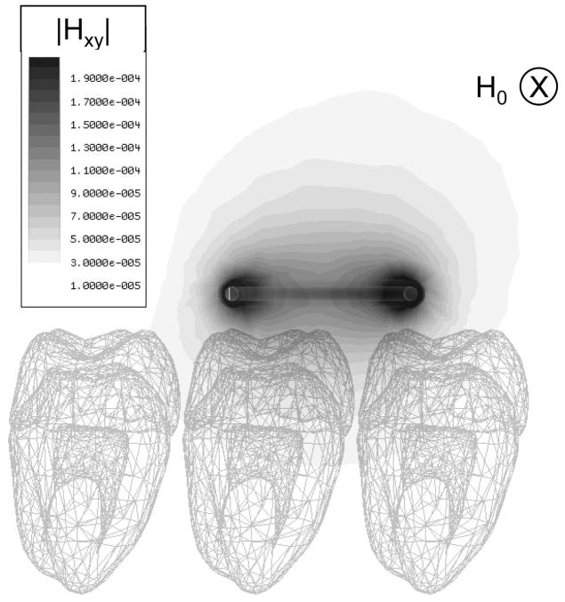
The HFSS simulation results in a vector map of the magnetic and electric components of the microwave field within the enamel and surrounding volume, from which a filling factor can be calculated. Fig. 2 shows a field map of the magnitude of the components of the magnetic field that are perpendicular to the static field through the cross-section of the molars. HFSS also provides an estimate of the quality factor and resonant frequency of the resonator, which depend on the dielectric losses within the sample.
Fig. 2.
A field map of Hxy, the magnitude of the components of the RF field perpendicular to the static field, is shown when the distance between the loop and molars is 1.25 mm. The static magnetic field, H0, is directed into the page as indicated.
An EPR signal is proportional to the microwave energy absorbed by the free electrons and is measured in volts. The performance of a resonator is characterized by the signal amplitude. A signal amplitude can be calculated (Feher 1957)
| (1) |
where χ is the magnetic susceptibility of the sample, η is the filling factor, Q0 is the unloaded quality factor with sample, and Pin is the incident microwave power. The magnetic susceptibility χ, is proportional to frequency; thus, when comparing two resonators with the same sample at the same frequency, this ratio is equal to unity. If, as in a simulation, the incident microwave power is assumed to be constant and the sample is not saturated, the signal amplitude is proportional to the product of η and Q, both of which depend on the positioning of the loop relative to the teeth under consideration. The filling factor is an indication of the amount of useful RF magnetic field in the tooth enamel. It drops off rapidly as the teeth are moved away from the loop. The filling factor is given by
| (2) |
where, UHc represents the total energy stored in the magnetic field of the entire simulation region and UHs is the energy stored in the sample by components of the RF magnetic field that are perpendicular to the static field (in the Z-direction). This can be further defined
| (3) |
where H is the value of the RF magnetic field, H* is the complex conjugate of the RF magnetic field and the volume of interest, and Vs is all the enamel present in a model. The quality factor, Q0, is a measure of the energy stored in a system to the energy dissipated, and it increases as the resonator is moved away from the molars and dielectric losses decrease. Lossy tissue, such as gums, degrades the Q0-values substantially and should be kept away from the RF field of the loop. In this work, the quantity ηQ0, which is unitless, is used to characterize the performance of each loop/tooth configuration.
RESULTS
Several simulations were conducted to evaluate the effects of the tissue surrounding the teeth and the tooth/loop positioning. The effects of tooth/loop positioning for a 10-mm circular loop are described. Since these simulations do not include the effects of the lossy tissue surrounding the teeth, it is shown that the presence of gums reduces the Q0-values. Finally, in vitro experimental verification of the HFSS calculations are provided.
Tooth/loop positioning
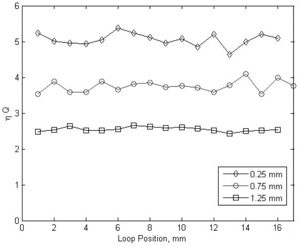
The effects of loop positioning were investigated using HFSS for a circular loop 10 mm in diameter. The product of the filling factor, η, and Q0-value for each position is plotted versus loop position for three different spacings between the loop and the molars in Fig. 3. For this investigation, the loop was moved along a row of three molars. When the loop is only 0.25 mm from the molars, the mean value of ηQ0 is 5.06 and the standard deviation is 0.17. Sensitivity of the EPR signal to loop position can be characterized by the relative deviation (defined as the standard deviation divided by the mean) of 0.0336. When the distance between the molars and loop is increased to 0.75 mm, the mean value of ηQ0 is 3.75, the standard deviation is 0.155 and the relative deviation is 0.0413. When the distance between the molars and loop is increased to 1.25 mm, the mean value of ηQ0 is 2.55, the standard deviation is 0.06, and the relative deviation is 0.0235.
Fig. 3.
ηQ0 is calculated for different loop/tooth positions as a 10-mm-diameter circular loop is translated along a row of molars. Each line represents a different spacing between the cusps of the molars and the bottom edge of the loop.
Accordingly, the sensitivity of the EPR signal to changes in position along a row of molars is reduced by 30% by spacing the loop away from the teeth. This is consistent with a general reduction in the microwave power within the enamel as the spacing increases, but a concomitant increase in the homogeneity of the microwave power within the enamel leads to a reduction in sensitivity to the irregular surfaces of the teeth. The magnitude of the signal is also reduced as the loop is moved away from the molars, but this could be addressed by increasing the incident power as the spacing is increased to maintain the microwave power within the enamel.
Dielectric losses in tissue
As shown in Fig. 4, the in vivo measurement of tooth enamel takes place surrounded by lossy tissue. Efforts are taken to distance the cheek and tongue from the measurement volume, but the tissue of the gums necessarily remains in closer proximity. Including such lossy tissue in the finite element model reduces the signal by significantly reducing the Q0-value. For example, the Q0-values predicted by HFSS for the model shown on the right side of Fig. 4 is 170. HFSS predicts the Q0-value to be 580 when only the loop and molars are present. The Q0-value obtained from the HFSS simulations correlates to the measured Q of existing resonators. For example, the typical measured Q for an empty resonator is between 450 and 500. The typical measured Q for a resonator in the mouth (as shown in Fig. 4) is between 175 and 225. The measured values of Q are consistent with the results obtained from the HFSS simulations.
Fig. 4.
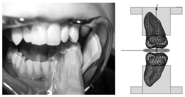
The picture on the left shows the in vivo measurement environment. The transmission line is seen and commercial dental putty is used to position the detection loop and separate the measurement region from the lossy tissue such as the tongue and cheek. The picture on the right shows the model used to simulate the in vivo measurement environment. The rectangular region surrounding the molars represents the gums in the FEA model.
Experimental vs. simulation results
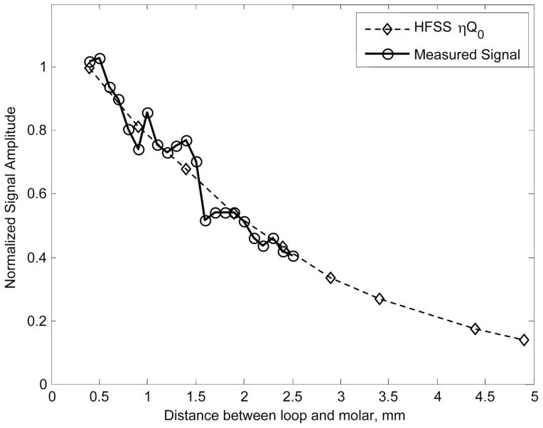
The normalized signal amplitude calculated from the HFSS results is compared to the in vitro measurements of a single molar. The results are shown in Fig. 5. The normalized signal amplitude is proportional to ηQ0 and has been scaled by a constant to account for different amplification factors between the experimental and simulated results. The normalized signal amplitudes decrease at the same rate for both the simulation and measurement, indicative of accuracy of the modeling used in the FEA simulations. It should be noted that the effects of saturation are not currently included in the described simulation. Both the native and radiation-induced EPR signals in tooth enamel are saturable (Iwasaki et al. 2005), and in the conventional experimental configuration with the detection loop of the resonator spaced ~0.25 mm above the surface of a molar tooth and a typical incident microware power of 50 mW, both signals are within saturation. However, the non-linearity introduced by saturation can be considered a second-order effect, and despite the exclusion of saturation effects in the simulation, the results here correspond well with the experimental data.
Fig. 5.
A comparison of the normalized signal amplitude predicted from the results of HFSS simulations and experimental measurements for a single isolated molar. The zero position is when the lower edge of the loop rests on the surface of the molar. The position is the relative distance between the molar and loop.
CONCLUSION
The potential value of the use of FEA using HFSS for the development of optimized surface loop resonators is indicated by the results described in this paper. The results here demonstrate that FEA of the resonator structures can accurately predict their experimental behaviors and that the simulations can be used to characterize the important effects of detector loop positioning and dielectric losses. It was shown that the measured Q0 of a resonator, with and without a sample, matched the Q0-value predicted by the HFSS simulations.
One of the most promising avenues to increase the sensitivity of EPR tooth dosimetry is the development of optimized resonators with a detection loop that are designed to optimally balance maximization of the EPR signal amplitude with minimization of the sensitivity to detection loop position. An example of an approach to accomplish this goal was described here. By increasing the separation between the tooth surface and the detection loop, a more uniform magnetic field is established over the tooth volume with decreased sensitivity to variation in position. This is reflected both by the decreased relative deviation of ηQ0 during translation across a row of teeth shown in Fig. 3 and the decreasing slope of the normalized signal amplitude shown in Fig. 5 for greater separations.
Another approach being investigated to optimize this compromise is the use of larger detection loops that average over greater volumes of tooth enamel to decrease sensitivity to fine anatomic features. In order to systematically perform this optimization with a number of interrelated design variables in a time-efficient manner, it is necessary to incorporate theoretical analysis and numerical simulation of the structures into the development plan. However, given the complexity of the detector loop shapes and enamel volumes, accurate simulations provide information that is not effectively addressed by pure theoretical analyses. It is expected that simulations such as these will provide critical guidance for the further development of resonators and measurement procedures for rapid, robust, field-deployable EPR tooth dosimetry for the screening of large populations potentially exposed to ionizing radiation.
Acknowledgments
This research was supported by DARPA (HR0011-08-C-0023) and NIH (U19AI067733).
References
- Brady JM, Aarestad NO, Swartz HM. In vivo dosimetry by electron spin resonance spectroscopy. Health Phys. 1968;15:43–47. doi: 10.1097/00004032-196807000-00007. [DOI] [PubMed] [Google Scholar]
- Feher G. Sensitivity considerations in microwave paramagnetic resonance absorption techniques. Bell System Technical J. 1957;36:449. [Google Scholar]
- Gordy W, Ard WB, Shields H. Microwave spectroscopy of biological substances. I. Paramagnetic resonance in x-irradiated amino acids and proteins. Proc Natl Acad Sci USA. 1955;41:983–996. doi: 10.1073/pnas.41.11.983. [DOI] [PMC free article] [PubMed] [Google Scholar]
- Hoshi N, Nikawa Y, Kawai K, Ebisu S. Application of microwaves and millimeter waves for the characterization of teeth for dental diagnosis and treatment. IEEE Transactions on Microwave Theory and Techniques. 1998;46:834–838. [Google Scholar]
- IFAC-CNR. [Accessed October 2008];Calculation of the dielectric properties of body tissues in the frequency range 10 Hz-100 GHz [online] Available at: http://niremf.ifac.cnr.it/tissprop/htmlclie/htmlclie.htm.
- Iwasaki A, Walczak T, Grinberg O, Swartz HM. Differentiation of the observed low frequency (1200 MHz) EPR signals in whole human teeth. Applied Radiat Isotopes. 2005a;62:133–139. doi: 10.1016/j.apradiso.2004.08.038. [DOI] [PubMed] [Google Scholar]
- Iwasaki A, Grinberg O, Walcsak T, Swartz HM. In vivo measurements of EPR signals in whole human teeth. Applied Radiat Isotopes. 2005b;62:187–190. doi: 10.1016/j.apradiso.2004.08.042. [DOI] [PubMed] [Google Scholar]
- Salikhov I, Hirata H, Walczak T, Swartz HM. An improved external loop resonator for in vivo L-band EPR spectroscopy. J Magnetic Resonance. 2003;164(1):54–59. doi: 10.1016/s1090-7807(03)00175-7. [DOI] [PubMed] [Google Scholar]
- Swartz HM, Burke G, Coey M, Demidenko E, Dong R, Grinberg O, Hilton J, Iwasaki A, Lesniewski P, Kmiec M, Lo K-M, Javier Nicolalde R, Ruuge A, Sakata Y, Sucheta A, Walczak T, Williams BB, Mitchell CA, Romanyukha A, Schauer DA. In vivo EPR for dosimetry. Radiat Meas. 2007;42:1075–1084. doi: 10.1016/j.radmeas.2007.05.023. [DOI] [PMC free article] [PubMed] [Google Scholar]
- Swartz HM, Iwasaki A, Walczak T, Demidenko E, Salikhov I, Khan N, Lesniewski P, Thomas J, Romanyukha A, Schauer D, Starewicz P. In vivo EPR dosimetry to quantify exposures to clinically significant doses of ionising radiation. Radiat Prot Dosim. 2006;120:163–170. doi: 10.1093/rpd/nci554. [DOI] [PubMed] [Google Scholar]
- Swartz HM, Iwasaki A, Walczak T, Demidenko E, Salikov I, Lesniewski P, Starewicz P, Schauer D, Romanyukha A. Measurements of clinically significant doses of ionizing radiation using non-invasive in vivo EPR spectroscopy of teeth in situ. Appl Radiat Isot. 2005;62:293–299. doi: 10.1016/j.apradiso.2004.08.016. [DOI] [PubMed] [Google Scholar]
- Walczak T, Lesniewski P, Salikov I, Szybinski K, Swartz HM. L-band electron paramagnetic resonance spectrometer for use in vivo and in studies of aqueous biological samples. Rev Sci Instrum. 2005;76:013107:1–6. [Google Scholar]
- Williams BB, Sucheta A, Dong R, Sakata Y, Iwasaki A, Burke G, Grinberg O, Lesniewski P, Kmiec M, Swartz HM. Experimental procedures for sensitive and reproducible in situ EPR tooth dosimetry. Radiat Meas. 2007;42:1094–1098. doi: 10.1016/j.radmeas.2007.05.001. [DOI] [PMC free article] [PubMed] [Google Scholar]


