Abstract
A unique method for incorporating functional porous polymer monolith elements into thermoplastic microfluidic chips is described. Monolith elements are formed in a microfabricated mold, rather than within the microchannels, and chemically functionalized off chip before insertion into solvent-softened thermoplastic microchannels during chip assembly. Because monoliths may be trimmed prior to final placement, control of their size, shape, and uniformity is greatly improved over in-situ photopolymerization methods. A characteristic trapezoidal profile facilitates rapid insertion and enables complete mechanical anchoring of the monolith periphery, eliminating the need for chemical attachment to the microchannel walls. Off-chip processing allows the parallel preparation of monoliths of differing compositions and surface chemistries in large batches. Multifunctional flow-through arrays of multiple monolith elements are demonstrated using this approach through the creation of a fluorescent immunosensor with integrated controls, and a microfluidic bubble separator comprising a combination of integrated hydrophobic and hydrophilic monolith elements.
Keywords: Thermoplastic, Microfluidics, Polymer Monolith, Biosensor, Immunosensor
1. Introduction
Polymer monoliths are a diverse class of porous materials that can be synthesized using a wide variety of monomers, crosslinkers, and polymerization techniques.[1] With pore sizes that can be tuned from the scale of hundreds of nanometers to tens of microns, polymer monoliths offer a ready alternative to packed particle beds and have been widely investigated for preparative and analytical applications where high surface area, controllable pore size, and adaptable surface chemistries are advantageous. More recently, polymer monoliths have been employed in microfluidic systems in a wide variety of roles.[2] Demonstrated microfluidic applications of porous monoliths include their use as frits for bead packing[3], cell lysis elements[4], support scaffolding for micro- and nanoparticles[4][5], three dimensional surfaces for antibody and enzyme immobilization[6][7], and stationary phases for chromatography or solid phase extraction.[8]
Monolith polymerization reactions take place within a solvent solution where individual precursor species exhibit higher solubility than polymerized reaction products. This differential solubility can be controlled by solvent choice or by tuning the solvent:precursor ratio. These parameters may be selected to adjust the rate at which newly polymerized reaction products phase separate and form solid interconnected globules, thereby providing control over morphology of the resulting monolith. In typical microfluidic applications, polymer monoliths are formed in situ at the desired locations within a fully assembled microfluidic chip by UV photopolymerization of a precursor solution injected into the channels, allowing photolithographic control over the final monolith dimensions. However, in situ integration presents a number of challenges that limit the potential for monoliths in microfluidic applications. Because the optical mask used during contact photolithography is necessarily displaced from the embedded microchannels by the thickness of the microfluidic cover plate, diffraction of light at the mask edges leads to significant variability in UV dose at the boundaries of the exposed region, resulting in poor control over the resolution of the resulting monoliths. In addition, diffusive transport of prepolymer components during the phase separation and polymerization process results in poor monolith homogeneity at the UV-exposed boundary. In particular, pore size and monolith density may differ drastically at the edges[9], affecting monolith performance for applications such as separations, biosensing, and filtration where uniform pore morphology is critical. Another constraint that limits the potential of porous monolith materials for microfluidic applications is that the in situ photopolymerization process requires a solution of monolith precursors, photoinitiators, and porogens to be injected into the microchannels prior to UV exposure, followed by extensive washing steps and any applicable functionalization operations needed to modify the monolith surface. These steps can be cumbersome and highly time consuming, with a typical device requiring a sequence of 3 or more perfusion steps performed over a period of several days. The incursion of precursor, wash, and functionalization solutions into other regions of the microfluidic system during the various perfusion steps can also affect the channel surface chemistry in unintended or undesirable ways. It should also be noted that In situ photopolymerization also necessitates the use of a UV-transparent chip material to allow for exposure through the top or bottom of the chip, limiting the range of substrate materials that can be used for integrated polymer monoliths. Additionally, the chip substrate must also be compatible with the solvent used to induce phase separation during polymerization, further limiting the substrate material options. A final limitation of in situ monoliths relates to the attachment of the porous material to the microchannel walls. Because polymer monoliths shrink both during photopolymerization and after aging, chemical attachment methods specific to the channel sidewall material must be implemented to minimize delamination from the channel walls. However, despite a variety of reported attachment schemes,[10][11] avoiding delamination remains a key challenge for microchannel-integrated monoliths. Because monoliths shrink in proportion to their size during polymerization, these attachment schemes become increasingly difficult in larger channels. This phenomenon, combined with the spatial limitations of masked photoinitiation, means that well sealed monoliths with high aspect ratio (hydrodynamic diameter to length) are exceedingly difficult to produce. Such high aspect ratio monoliths are desirable in applications where a high flow rate or low pressure are required.
As a way to sidestep some of these constraints, Hisamoto et al. developed a method for integrating capillary-encased monolith segments into a PDMS chip.[12] In this case, glass capillaries with rectangular cross-section were used to provide structural integrity during insertion into the on-chip channel. This hybrid glass/elastomer approach allows for covalent attachment between the glass and monolith surfaces, but monolith attachment to the inner wall of the capillary requires additional surface treatment steps. While the method can potentially be adapted for batch processing of large numbers of monolith segments, the overall capillary integration process imposes a mismatch in cross-sectional dimensions between the PDMS channels and capillary-supported monoliths, resulting in a dead volume at the fluidic interfaces between each capillary and mating microchannel. In addition, the technique relies on compliant elastomer channel walls for effective leak-free integration of the silica capillaries, and cannot be readily adapted to thermoplastic microfluidic chips fabricated using traditional bonding strategies.
Here we report an entirely different method for the incorporation of discrete high aspect ratio polymer monolith elements into thermoplastic microfluidic chips that relies on ex situ fabrication and functionalization of bare monolith elements, followed by solvent-assisted integration of the preformed monoliths into the final microfluidic system. The technique allows for multiple monolith elements of differing chemistry, porosity, or functionality to be fabricated off-chip in a parallel batch process before integration of one or more discrete elements into the final device. This approach provides greatly enhanced processing throughput over in situ monolith preparation by eliminating the need for sequential processing steps to be performed on-chip for the preparation of single monolith zones, and further allowing multiple monoliths with different surface and bulk properties to be integrated within a single microfluidic chip using a unified fabrication process. The utility of the ex situ integration method is demonstrated through fabrication of a multi-element immunosensor as well as a microfluidic wettability-based bubble separator composed of closely spaced hydrophobic and hydrophilic monoliths.
2. Materials and methods
2.1 Materials
Glycidyl methacrylate (GMA), butylmethacrylate (BMA), ethylenedimethacrylate (EDMA), 1,4-butanediol, 1-propanol, cyclohexanol, methanol, ethanol, 2,2-dimethoxy-2-phenylacetophenone (DMPA), sodium phosphate dibasic, N-[γ-maleimidobutyryloxy]succinimide ester (GMBS), bovine serum albumin (BSA), rhodamine B, and decahydronaphthalene (decalin) were purchased from Sigma–Aldrich (St. Louis, MO). Ethoxylated trimethylolpropane triacrylate (SR454) was received as a free sample from Sartomer (Warrington, PA). IgG-FITC from human serum and protein G’ from Streptococcus were both purchased from Sigma Aldrich. Cyclic olefin copolymer (COC; grade 1020R) was purchased from Zeon Chemicals (Louisville, KY).
2.2 Chip preparation
Microfluidic channels were directly milled into 2 mm thick plaques of COC using a Roland MDX-650 CNC router. Rectangular cross-section channels were fabricated using square end mills. Trapezoidal cross-section channels were fabricated using a trapezoidal-tipped end mill made by blunting the tip of a 90° pointed end mill to produce a modified tool with a 100 μm diameter flat bottom and edges slanted at 45° from the surface normal.
2.3 Monolith formation and functionalization
Discrete monolith elements were formed in temporarily-sealed mold microchannels, following an established monolith photopolymerization method.[6] The molding microchannels were formed by covering open trenches milled in a COC substrate with a capping layer of PDMS or electrical tape. Measures to promote attachment to the COC channel walls were omitted to ensure ready removal of the monoliths from the molding microchannels following polymerization. Briefly, a pre-monolith solution of 24% GMA, 16% SR454, 50% cyclohexanol, and 10% methanol (by weight) was prepared. Photoinitiator (DMPA) equaling 1% of the combined weight of the GMA and SR454 was added to the solution. The molding channels were then filled with the solution, and the access holes were also sealed with electrical tape. Photopolymerization of the monoliths was accomplished with a UV light source (PRX-1000; Tamarack Scientific, Corona, CA) outputting 22 mW/cm2 for 600 s. After photopolymerization, the layer of tape was peeled away and intact monoliths were removed from the open channels with tweezers, cleaved or cut to a prescribed length, and soaked in methanol followed by 20% methanol in water under gentle agitation on a laboratory shaker to remove solvent and any unreacted prepolymer. Optimal cutting results were achieved by placing the extracted monolith on a flat surface and manually slicing the initial element with a razor blade to form discrete segments of the desired length. While more precise patterning may be possible by automating the process, for example by employing a wafer dicing saw, cutting of monoliths to lengths of approximately 200 ~ 250 μm was found to be readily feasible through the manual process. Further functionalization, as described below, and final rinse steps were performed in small glass vials with gentle manual agitation. BMA monoliths were formed using the same procedure with a mixture of 23.5% BMA, 15.5% EDMA, 34% 1,4butanediol, 26% 1-propanol and 1% DMPA.
2.4 Protein and fluorescent dye attachment
A previously reported[6] method for protein immobilization on GMA monoliths was used. Briefly, monolith elements are immersed for 2 hr in a 2M solution of sodium hydrosulfide in a mixture of 20% methanol and 80% 0.1 M sodium phosphate dibasic at pH 8.15 to convert epoxide groups to thiols. Remaining epoxide groups are eliminated by treatment overnight with 0.5M sulfuric acid. Monoliths are then incubated in a 2 mM solution of GMBS in ethanol prior to reaction with the desired protein over a concentration range of 50–500 μg/mL for 1 hr in PBS.
2.5 Monolith reintegration, and chip bonding
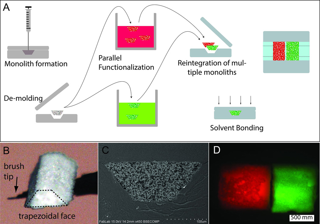
In lieu of chemical attachment to the channel walls, anchoring and fluidic sealing of the reintegrated monoliths is accomplished during the solvent bonding process while the channel walls are temporarily softened by decalin exposure. The flat capping layer of the chip is exposed to a solution of decalin in ethanol, as previously reported as part of a liquid-phase COC solvent bonding procedure.[13] A small volume (1-5 μL) of the same solvent solution is pipetted into the region of the channel where the monolith is to be placed. A solution of 20% decalin in ethanol was found to be most effective to achieve full sealing between the thermoplastic and monolith surfaces while preventing distortion of the microchannels during bonding. After 10 min, the two COC surfaces are washed in 100% ethanol and dried quickly with a stream of nitrogen to prevent further solvent uptake. The monolith elements are then manually positioned at the desired locations in the channel using a wet fine-tipped brush (Figure 1B) which weakly adheres to the hydrophilic monolith by capillary forces, and the capping layer is sealed to the channel substrate using a pressure of 3.5 MPa for 20 min at 60°C. To account for monolith shrinkage during processing, the channels receiving the monoliths are fabricated with depths between 5–10% smaller than the monolith formation channels to ensure full sealing at the periphery of the monolith.
Fig. 1.
(A) Schematic of monolith formation in a thermoplastic mold followed by batch cleanup and functionalization, and finally reintegration and chip bonding. (B) Optical micrograph of a trapezoidal monolith element (maximum width and length approximately 200 μm and 400 μm) manipulated with a fine paint brush. (C) SEM image of a Trapezoidal monolith element after reintegration into a COC chip. (D) Two monoliths integrated into the same channel. Left monolith with covalently attached rhodamine, right monolith with covalently attached IgG-FITC.
3. Results and Discussion
3.1 Monolith Integration
The solvent-assisted monolith integration process relies on the insertion of a preformed monolith into a mating thermoplastic channel with cross-sectional dimensions slightly smaller that of the monolith itself. By softening the thermoplastic with a suitable solvent, the monolith is forced into the bulk thermoplastic during bonding, resulting in an intimate seal between the materials. In a typical microfluidic chip, open channels with vertical sidewalls are formed in a planar substrate before being enclosed during bonding with a second substrate, resulting in sealed channels with rectangular cross-sections. While insertion of an oversized monolith into a rectangular channel prior to sealing is possible, this approach was found to be challenging to implement manually since vertical alignment must be maintained during insertion to avoid collision with either side-wall. Additionally, because the monolith must be slightly oversized to ensure a good seal with the channel walls, high forces are required during insertion which can result in monolith fracture. As a result, yield for intact monoliths reintegrated into rectangular cross-section channels was found to be poor. To overcome these issues, we explored the use of monoliths and microchannels with triangular or trapezoidal cross-sections.
Using a channel with a triangular or trapezoidal cross-section greatly simplifies the alignment and insertion of monoliths with nearly-matched cross-sections during the initial steps of reintegration. For the monolith geometries reported here, the elements self-assemble into their final positions within the channels. The fluidic self-assembly process consists of depositing a small droplet of water containing a single monolith element at the desired insertion location. Due to its shape, the deposited trapezoidal monolith docks with the receiving channel in its preferred orientation without the need for careful alignment with the channel. This self-assembly approach is demonstrated in Figure 2. A monolith element suspended in a drop of water is positioned over an open trapezoidal channel using a pipette. Gentle agitation together with capillary forces serve to move the monolith until it enters the mating channel to maximize surface area contact with the microchannel substrate. While the angled sidewalls of the channels and monoliths encourage seating of the monoliths into the desired configuration, monoliths occasionally enter the channel in an improper orientation. In this event the droplet is readily retracted by pipette before repeating the process.
Fig. 2.
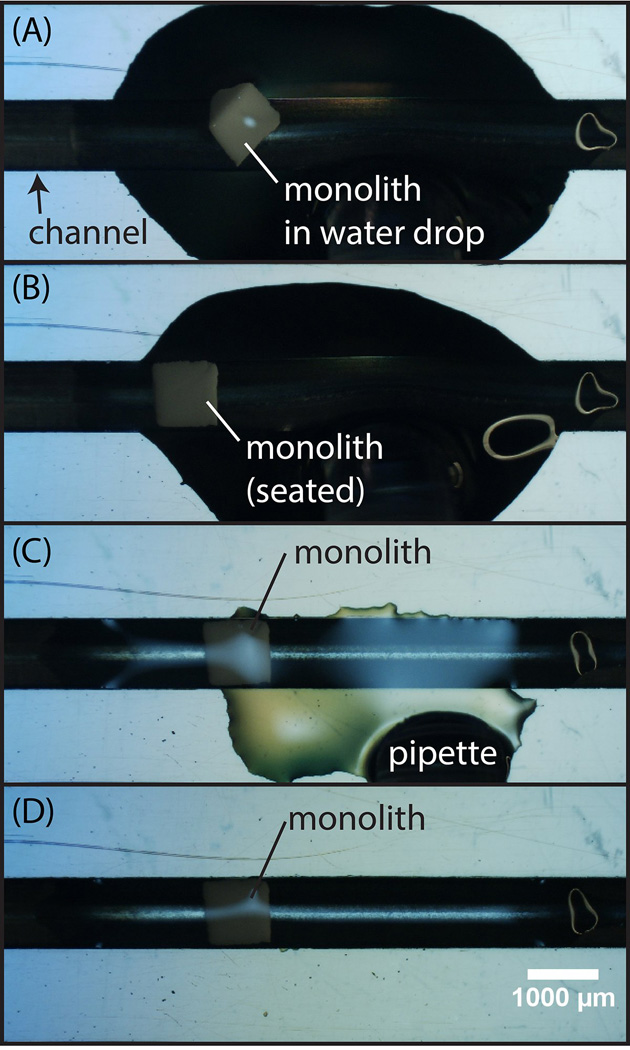
Overview of the monolith self-assembly process (A) A single monolith element suspended in water is drawn into a pipette and deposited within a droplet onto the microchannel substrate. (B) Under the influence of gentle agitation, the trapezoidal monolith seats into the channel in its preferred orientation maximizing surface contact with the sloped channel sidewalls. (C) To accelerate the insertion process, the water droplet is removed by pipette, followed by (D) drying of the substrate prior to solvent bonding.
The brittle nature of the porous polymer monoliths used in this study presents practical limitations on monolith length to width ratio (L/W). Longer re-integrated monolith elements (L/W > 10) proved difficult to handle without fracture. For shorter monolith elements (L/W < 0.25), unreliable alignment with the channel during the self-insertion process limited device yield. In addition, complete and gap-free anchoring of the shorter monoliths to the channel walls could not be consistently achieved. For consistent results, ratios within the range of 0.5 < L/W < 2 are generally desirable.
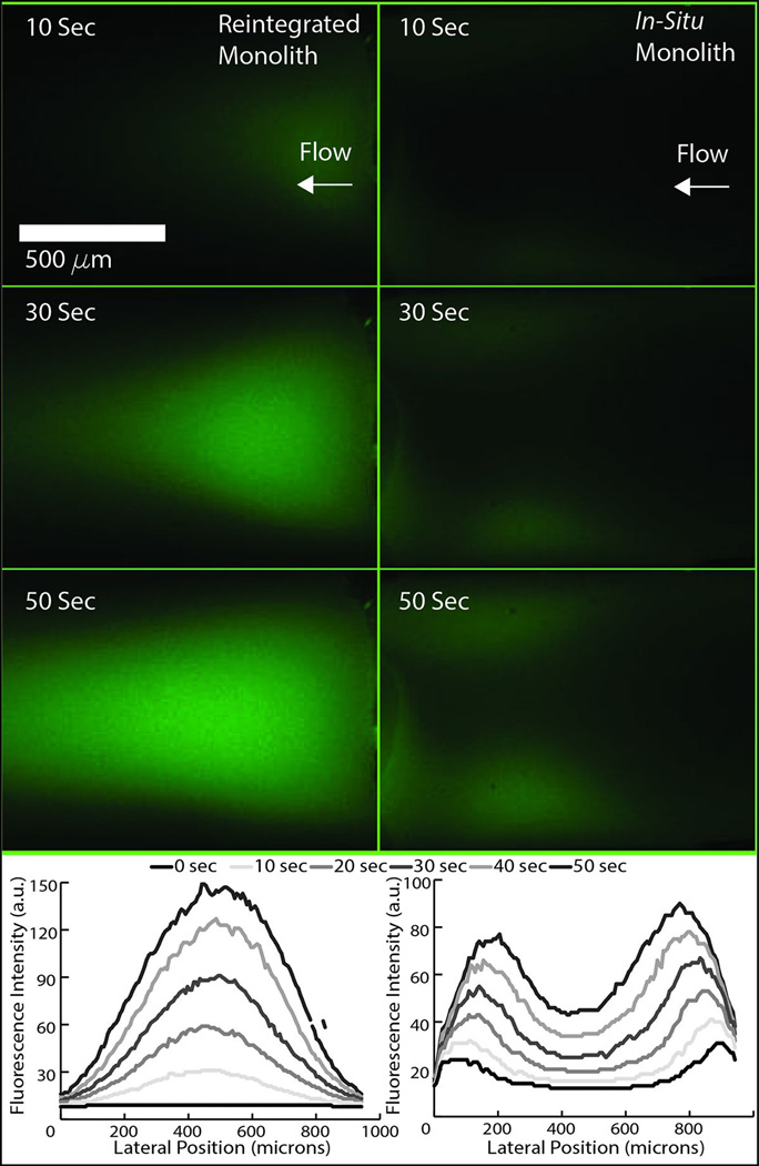
In addition to supporting effective self-assembly of monolith elements into their mating channels during insertion, the slanted sidewalls also ensure that each surface experiences a normal force during bonding that serves to embed the monolith within the bulk polymer during chip bonding. The utility of monoliths for microfluidic applications derives primarily from their controllable porosity and high surface area, and thus the ability to eliminate voids and achieve high bond strength between the microchannel walls and monolith surfaces is critical for ensuring predictable and uniform flow through the porous structures. Compared with traditional in situ monolith fabrication, the solvent-assisted reintegration process provides excellent monolith-COC anchoring due to mechanical interlocking between the materials. A typical example of the interface between the monolith and COC channel wall following bonding that reveals the morphology of the interlocking materials is shown in Figure 3. To evaluate the quality of the interface, a dilute fluorescein solution was pumped at 2 μL/min for 5 min to 10 min through a reintegrated monolith as well as a monolith formed in situ within an identical microchannel. Care was taken to produce monoliths of similar lengths (approximately 2 mm) for each case.. A time sequence of images revealing the resulting flow profiles within each monolith are shown in Figure 4. As shown in this figure, flow through the reintegrated monolith occurs within the bulk porous matrix, with uniform fluorescence intensity that matches well with the trapezoidal cross-section of the monolith. In contrast, flow through the in situ monolith occurs primarily at the monolith-microchannel interface, indicating the presence of extensive voids between the materials that result in a non-uniform flow profile and prevent significant flow through the core of the porous structure. For properly sealed monoliths, regardless of monolith dimensions, anchoring between the monoliths and channel walls was excellent, with no delamination or bulk motion of the monolith elements observed for all tested flow rates up to 100 μL/min.
Fig. 3.
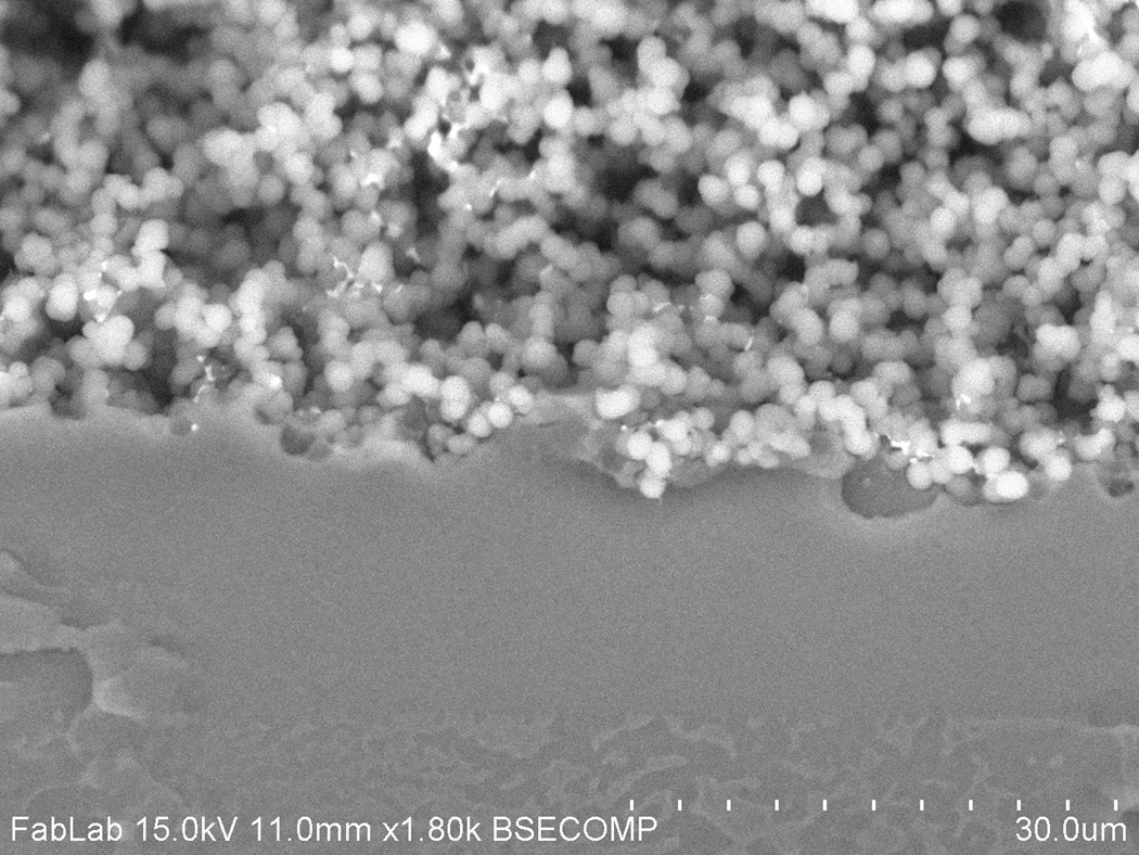
SEM image of a typical monolith-COC interface in a reintegrated monolith chip. Mechanical interlocking of the materials occurs as the porous monolith is pressed into the solvent-softened bulk thermoplastic substrate.
Fig. 4.
Fluorescence images of fluorescein solution being pumped through a reintegrated monolith (left column) and a monolith formed in-situ in a microchannel (right column). A time progression of fluorescence intensity profiles is shown for each case.
3.2 Multifunctional Monolith Arrays
One application of microfluidic monoliths that holds particular promise is in the area of optofluidic sensing, where the porous matrix serves as a functionalized volumetric detection zone capable of enhancing local analyte concentration and detection sensitivity.[14][6] By integrating an array of porous elements with different chemical or biochemical functionalities within a single device, this approach can provide a path to multiplexed detection of different analytes within a single sample. A variety of strategies have been reported for the integration of arrays of porous or 3-dimensional detection elements into microfluidic chips including integration of discrete functionalized capillary segments,[15] patterning of hydrogel micropatches,[16] and 1-dimensional microbead arrays.[17] For the case of porous monoliths, the in situ formation of a multifunctional array within a sealed microchannel is possible, but this approach would require a laborious sequential fabrication process,[18] together with the need for complex flow control to deliver separate functionalization reagents to each array element.
The reintegration of fully functionalized ex situ monolith elements using the approach described here can avoid these limitations, allowing facile construction of arrays of sealed polymer monolith elements with different functionalities within a single continuous microchannel or microfluidic network. Due to its low volatility relative to other commonly used solvents, the use of decalin for solvent bonding allows the COC surface to remain softened for up to several minutes following solvent exposure, providing ample time for manual integration of multiple monolith elements to enable the creation of closely spaced arrays. An illustrative example of this capability is presented in Figure 1D, where monolith elements batch-functionalized with two different fluorescent markers (rhodamine and FITC) are placed immediately adjacent to each other within a single channel, with no overlap and minimal buffer space between the elements.
Using this approach, a simple flow-through immunoassay with integrated positive and negative controls was realized (see Figure 5). In this example device an un-functionalized monolith incubated with BSA is used as a negative control which indicates the extent of non-specific analyte binding. A second monolith functionalized with covalently-attached protein G is used as the detection element for FITC-IgG, while a third monolith with covalently-attached FITC-IgG provides a positive control fluorescence standard against which the detection element fluorescence is compared for quantitative readout. Before FITC-IgG is perfused through the channel as a model analyte, only the positive control is visible under fluorescence microscopy using a FITC filter set. After a solution of 100 μg/mL FITC-IgG in PBS is perfused through the series of monoliths at 5 μL/min for 20 min, followed by an equal flow rate and volume of rinse buffer, the fluorescence intensity in the other two monoliths increases to the levels seen in Figure 5B. The high fluorescence intensity observed for the covalently-anchored FITC-IgG used as the positive control reveals that the chip bonding process does not result in significant loss of anchored biomolecules. Similarly, the demonstration of FITC-IgG capture by monolith-anchored IgG shows that chip bonding using the given conditions does not result in degradation or conformational changes in the anchored molecules that would prohibit effective antibody-antigen interactions. This concept may be readily extended to include additional monolith elements functionalized with other capture probes to realize higher levels of multiplexing in a simple flow-through assay.
Fig. 5.
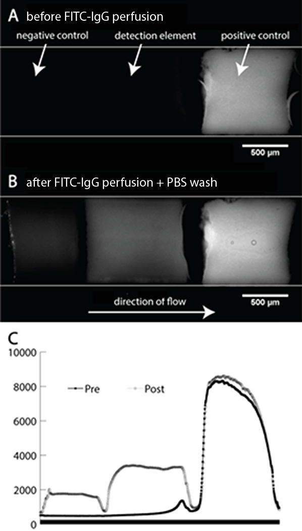
(A) Monolith immunosensor with multiple elements before analyte exposure. Negative control and detection element show no signal. (B) The same immunosensor after exposure. The negative control element provides a measure of nonspecific binding while the brighter detection element shows successful antibody capture. Comparison of the detection element fluorescence and fluorescence from the positive control provide a quantitative measure of analyte concentration in the sample. (C) Graphs of fluorescence intensity as a function of channel position through the monolith array (averaged across the channel width).
3.3 Wettability-based bubble separators
The formation of unwanted air bubbles is a common challenge for many microfluidic systems. Here we take advantage of the ability to integrate multiple porous structures with different chemistries to demonstrate a strategy for removing trapped air from a microchannel based on the differential wettability. As shown in Figure 6, a hydrophobic BMA monolith and a hydrophilic GMA monolith, each approximately 1 mm long, 1 mm wide, and 350 μm deep were integrated within each downstream branch adjacent to the inlet of a T-junction, completely blocking each channel. At low inlet pressures the pores of the hydrophobic BMA monolith remain air filled and present a low resistance to gas flow. Likewise, the pores of the hydrophilic GMA monolith wet readily and spontaneously fill with water by capillary flow. To test the device, water was pumped at 5 μL/min through the inlet channel, with air bubbles introduced using an off-chip flow splitter. One full cycle of water-air-water injection is presented in Figure 6, revealing complete removal of the air bubble through the hydrophobic monolith and an isolated flow of water achieved through the hydrophilic monolith.
Fig. 6.
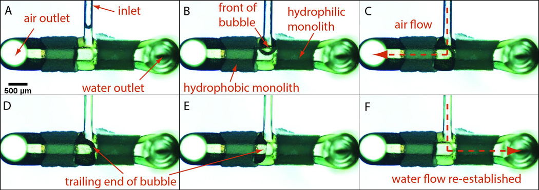
Separation of air and water from a two phase flow in a wettability-based bubble separator. (A)–(B). An air bubble enters the separator, displacing the remaining water at the channel intersection through the hydrophilic GMA monolith. (C)–(D) The air bubble traverses the hydrophobic BMA monolith element, and finally clears the gap between the two monoliths. (E)–(F) Water behind the trailing edge of the bubble re-establishes flow through the wet GMA as the remainder of the air bubble enters the dry BMA monolith.
It should be emphasized that in this example, two different monolith chemistries were used, unlike the previous multiplexed immunosensor example which took advantage of different functionalization paths with a single monolith chemistry. Indeed, driven largely by their use increasing in chromatographic separations, an exceptionally wide range of demonstrated polymer monolith chemistries[19] beyond glycidyl and butyl methacrylates can be readily adapted to the solvent-assisted integration process. Similarly, a vast array of inorganic metal and oxide monolith chemistries,[20] many of which require high temperature synthesis that prohibits their integration into thermoplastic microfluidics by in situ fabrication, can potentially be integrated via the solvent-assisted process. It is also notable that the choice of monolith material is not limited by sidewall anchoring requirements, since the solvent-assisted process employs mechanical interlocking rather than chemistry-specific covalent attachment,
4. Conclusion
The integration of pre-fabricated and pre-functionalized monoliths into thermoplastic microfluidic devices by the solvent-assisted process has the potential to greatly simplify the preparation of a wide variety of microfluidic devices. The process allows porous, high surface area, and both chemically- and functionally-diverse monolith structures to be prepared off chip in a highly parallel batch process, followed by post-synthesis insertion into fully sealed microfluidic channels without concern for traditional limits on monolith homogeneity, resolution, and chemical compatibility with the microfluidic substrate. The process allows multiple monolith elements with different surface functionalities or bulk polymer chemistries to be used within a single device, and the concept may be further extended to other monolith materials including inorganic oxides or metals, significantly widening the range of porous materials that may be integrated into thermoplastic microfluidics. While the method has been demonstrated here for immunosensing and bubble removal, the technique can offer wide utility for applications including molecular separation and solid phase extraction, filtration, biosensing, microreaction, sample purification, and beyond.
Acknowledgements
This research was supported in part by funding from Canon U.S. Life Sciences, Inc., by NIH grant R01AI096215, and by the DARPA N/MEMS S&T Fundamentals Program under grant no. N66001-1-4003 issued by the Space and Naval Warfare Systems Center Pacific (SPAWAR) to the Micro/nano Fluidics Fundamentals Focus (MF3) Center. Electron microscopy was performed with facilities and support of the Maryland Nanocenter.
Biographies
Eric L. Kendall is a Postdoctoral Scholar at the University of Maryland, College park in the Maryland MEMS and Microfluidics Laboratory. He received his B.S. from the University of California, San Diego in 2002 and his Ph.D. from the University of California, Davis in 2010, both in Chemical Engineering. His current research focus is on development novel fabrication methods for microfluidics devices for biological sample preparation and analysis applications.
Erik Wienhold received his B.S. in 2013 from the University of Maryland, College Park in Materials Science and Engineering. He currently works at Slipchip LLC in Pasadena, CA.
Omid D. Rahmanian received his B.S degree from the Department of Bioengineering at the University of California, Berkeley. He is currently an ARCS Scholar, and a Ph.D candidate at the Maryland MEMS and Microfluidics Laboratory.
Don L. DeVoe is a Professor in the Department of Mechanical Engineering at the University of Maryland, with an affiliate appointment in the Fischell Department of Bioengineering. He received his Ph.D. in Mechanical Engineering from U.C. Berkeley in 1997, with a focus in piezoelectric MEMS. His current research interests include microfluidic bioanalytical technologies and piezoelectric microsystems.
Footnotes
Publisher's Disclaimer: This is a PDF file of an unedited manuscript that has been accepted for publication. As a service to our customers we are providing this early version of the manuscript. The manuscript will undergo copyediting, typesetting, and review of the resulting proof before it is published in its final citable form. Please note that during the production process errors may be discovered which could affect the content, and all legal disclaimers that apply to the journal pertain.
Notes and references
- 1.Svec F. Porous polymer monoliths: amazingly wide variety of techniques enabling their preparation. J. Chromatogr. A. 2010;1217:902–924. doi: 10.1016/j.chroma.2009.09.073. [DOI] [PMC free article] [PubMed] [Google Scholar]
- 2.Vázquez M, Paull B. Review on recent and advanced applications of monoliths and related porous polymer gels in micro-fluidic devices. Anal. Chim. Acta. 2010;668:100–113. doi: 10.1016/j.aca.2010.04.033. [DOI] [PubMed] [Google Scholar]
- 3.Zeng S, Chen C, Santiago JG, Chen J, Zare RN, Tripp JA, et al. Electroosmotic flow pumps with polymer frits. 2002;82:209–212. [Google Scholar]
- 4.Mahalanabis M, Al-Muayad H, Kulinski MD, Altman D, Klapperich CM. Cell lysis and DNA extraction of gram-positive and gram-negative bacteria from whole blood in a disposable microfluidic chip. Lab Chip. 2009;9:2811–2817. doi: 10.1039/b905065p. [DOI] [PubMed] [Google Scholar]
- 5.Liu J, White I, DeVoe DL. Nanoparticle-functionalized porous polymer monolith detection elements for surface-enhanced Raman scattering. Anal. Chem. 2011;83:2119–2124. doi: 10.1021/ac102932d. [DOI] [PMC free article] [PubMed] [Google Scholar]
- 6.Liu J, Chen C-F, Chang C-W, DeVoe DL. Flow-through immunosensors using antibody-immobilized polymer monoliths. Biosens. Bioelectron. 2010;26:182–188. doi: 10.1016/j.bios.2010.06.007. [DOI] [PMC free article] [PubMed] [Google Scholar]
- 7.Peterson DS, Rohr T, Svec F, Fréchet JMJ. Enzymatic microreactor-on-a-chip: protein mapping using trypsin immobilized on porous polymer monoliths molded in channels of microfluidic devices. Anal. Chem. 2002;74:4081–4088. doi: 10.1021/ac020180q. [DOI] [PubMed] [Google Scholar]
- 8.Liu J, Chen C-F, Tsao C-W, Chang C-C, Chu C-C, DeVoe DL. Polymer Microchips Integrating Solid-Phase Extraction and High-Performance Liquid Chromatography Using Reversed-Phase Polymethacrylate Monoliths. Anal. Chem. 2009;81:2545–2554. doi: 10.1021/ac802359e. [DOI] [PMC free article] [PubMed] [Google Scholar]
- 9.He M, Bao J-B, Zeng Y, Harrison DJ. Parameters governing reproducibility of flow properties of porous monoliths photopatterned within microfluidic channels. Electrophoresis. 2010;31:2422–2428. doi: 10.1002/elps.200900774. [DOI] [PubMed] [Google Scholar]
- 10.Stachowiak TB, Rohr T, Hilder EF, Peterson DS, Yi M, Svec F, et al. Fabrication of porous polymer monoliths covalently attached to the walls of channels in plastic microdevices. Electrophoresis. 2003;24:3689–3693. doi: 10.1002/elps.200305536. [DOI] [PubMed] [Google Scholar]
- 11.Nischang I, Brueggemann O, Svec F. Advances in the preparation of porous polymer monoliths in capillaries and microfluidic chips with focus on morphological aspects. Anal. Bioanal. Chem. 2010;397:953–960. doi: 10.1007/s00216-010-3550-x. [DOI] [PubMed] [Google Scholar]
- 12.Hisamoto H, Funano S, Terabe S. Integration of valving and sensing on a capillary-assembled microchip. Anal. Chem. 2005;77:2266–2271. doi: 10.1021/ac0484528. [DOI] [PubMed] [Google Scholar]
- 13.Wallow TI, Morales AM, a Simmons B, Hunter MC, Krafcik KL, a Domeier L, et al. Low-distortion, high-strength bonding of thermoplastic microfluidic devices employing case-II diffusion-mediated permeant activation. Lab Chip. 2007;7:1825–1831. doi: 10.1039/b710175a. [DOI] [PubMed] [Google Scholar]
- 14.Jiang K, Sposito A, Liu J, Raghavan SR, DeVoe DL. Microfluidic synthesis of macroporous polymer immunobeads. Polymer (Guildf) 2012;53:5469–5475. [Google Scholar]
- 15.Hisamoto H, Nakashima Y, Kitamura C, Funano S-I, Yasuoka M, Morishima K, et al. Capillary-assembled microchip for universal integration of various chemical functions onto a single microfluidic device. Anal. Chem. 2004;76:3222–3228. doi: 10.1021/ac035385t. [DOI] [PubMed] [Google Scholar]
- 16.Heo J, Crooks RM. Microfluidic biosensor based on an array of hydrogel-entrapped enzymes. Anal. Chem. 2005;77:6843–6851. doi: 10.1021/ac0507993. [DOI] [PubMed] [Google Scholar]
- 17.Zhang H, Yang X, Wang K, Tan W, Zhou L, Zuo X, et al. Detection of single-base mutations using 1-D microfluidic beads array. Electrophoresis. 2007;28:4668–4678. doi: 10.1002/elps.200700048. [DOI] [PubMed] [Google Scholar]
- 18.Ro KW, Nayak R, Knapp DR. Monolithic media in microfluidic devices for proteomics. Electrophoresis. 2006;27:3547–3558. doi: 10.1002/elps.200600058. [DOI] [PubMed] [Google Scholar]
- 19.Svec F. Porous polymer monoliths: amazingly wide variety of techniques enabling their preparation. J. Chromatogr. A. 2010;1217:902–924. doi: 10.1016/j.chroma.2009.09.073. [DOI] [PMC free article] [PubMed] [Google Scholar]
- 20.Walsh Z, Paull B, Macka M. Inorganic monoliths in separation science: a review. Anal. Chim. Acta. 2012;750:28–47. doi: 10.1016/j.aca.2012.04.029. [DOI] [PubMed] [Google Scholar]


