

Abstract
Visual impairment affects over 285 million people worldwide and has a major impact on an individual’s quality of life. Tissue engineering has the potential to increase quality of life for many of these patients by preventing vision loss or restoring vision using cell-based therapies. However, these strategies will require an understanding of the microenvironmental factors that influence cell behavior. The eye is a well-organized organ whose structural complexity is essential for proper function. Interactions between ocular cells and their highly ordered extracellular matrix are necessary for maintaining key tissue properties including corneal transparency and retinal lamination. Therefore, it is not surprising that culturing these cells in vitro on traditional flat substrates result in irregular morphology. Instead, topographically patterned biomaterials better mimic native extracellular matrix and have been shown to elicit in vivo-like morphology and gene expression which is essential for tissue engineering. Herein we review multiple methods for producing well-controlled topography and discuss optimal biomaterial scaffold design for cells of the cornea, retina, and lens.
INTRODUCTION
An estimated 285 million people are visually impaired including 39 million who are considered blind [1]. Visual impairment severely reduces quality of life and can have major socioeconomic implications [2]. The leading causes of blindness include corneal opacities, age-related macular degeneration (AMD), diabetic retinopathy, and cataract, all of which are caused by cell death or dysfunction [1,3]. Tissue engineering may have the potential to treat theses causes of blindness by replacing diseased or damaged tissue with healthy tissue. However, the use of cell-based strategies to restore vision or prevent vision loss will require not only the proper cell types, but also the proper organization and function of these cells.
Cell behavior is influenced by a combination of soluble factors, direct cell-cell interactions, the insoluble extracellular matrix (ECM), mechanical forces, and electrical stimuli [4,5]. In addition to providing biological protein-based signaling, the ECM also presents physical cues including topography that mediate cell function [6]. The major components of the ECM include collagen, elastin, laminin, and fibronectin. These structural proteins have nanoscale molecular structure, but can also form higher order multi-molecular units on the microscale [4,7–12]. As a result, biomimetic tissue engineering scaffolds that recreate the physical architecture of a cell type’s native environment may enhance cell function for therapeutic applications [13]. However, exploring this hypothesis has been exceptionally difficult due to the large number of confounding factors influencing cell function and limited knowledge of the underlying molecular pathways. Comparing studies that examine the effect of topography on cells has been practically challenging due to the infinite number of potential topographies and variations in experimental parameters between research groups. Further complicating this process is the fact that the effect of topography can vary greatly between similar cell types [14], adjacent cell types [15], and even within the same cell type from different species [16] which makes obtaining far-reaching conclusions about the effect of a particular topography difficult.
The idea that nanoscale ECM topography plays a role in cell behavior was first formalized by Rosenberg in 1962 [17, 18]. Since then many studies have shown that surface topography can influence cell proliferation [19, 20], morphology [21–23], migration [23–25], differentiation [26–28], gene expression [9,29,30], and function [31,32]. Cell attachment is mediated by integrin binding which links the cell’s cytoskeleton to the substrate which can affect nucleus conformation and thus gene expression along with its downstream outcomes [32,33]. Typical patterns used in topographical studies include grooves (alternating ridges and troughs), posts, wells, or a combination of these patterns [30,34,35]. The mechanism of action through which surface topography mediates these functions has yet to be fully elucidated [35], but prevailing theories point to the availability and orientation of surface area [4], topography-directed mechanotransduction [5], and/or topography-dependent protein adsorption [36]. When cells bind to patterned material surfaces these attachments occur preferentially in a particular area with orientation based on the geometry and accessible surface area [14]. For example, a cell on tightly-spaced nanogrooves may preferentially align itself parallel to the grooves by binding to only the tops of ridges if the spacing is sufficiently small to prevent the penetration of cell processes into the troughs [14,37]. Likewise, if the ridge spacing is large, the processes or even entire cells may be able to bind securely to the three-dimensional topography and increase cell adhesion [38]. Additionally, several groups have reported that substrate topography can also influence the organization of ECM produced by adherent cells [39,40]. The potential ramifications of this discovery are quite substantial as it suggests a method for creating natural scaffolds composed of well-organized ECM and suggests the persistence of topographical cues even after a scaffold has degraded or been removed.
This review focuses specifically on the effect of highly-ordered nano- and microtopography on ocular cell behavior for therapeutic applications. The use of well-controlled methods has been chosen because they are essential for systematically studying the effect of individual variables on cell behavior. In addition, several groups have shown that feature regularity and symmetry may also regulate cell behavior [36, 41]. For these reasons random fabrication techniques such as electrospinning, which produces poorly-controlled topography, have not been included.
FABRICATION TECHNIQUES
1. Overview
Although well-ordered features are generally more labor-intensive and expensive to create than their random counterparts, their unmatched precision is critical for studying cell response to topography at the length scale of ECM. The techniques for producing these topographies can be categorized as top-down or bottom-up. Top-down methods rely on removing molecules from the starting substrate to produce topography and are typically flexible, but expensive. Alternately, bottom-up methods involve the addition of material onto the substrate and are less expensive, but offer fewer patterning options [42]. Because of the miniscule length scale, there are only a few well-controlled techniques capable of producing a pattern with nanoscale resolution; therefore, many of the fabrication processes discussed below share one or more processing steps, namely nanolithography as shown in Figure 1. However, each process included here has been chosen because it provides some advantage in feasibility (cost, time, machinery requirements, reproducibility, complexity, material compatibility, etc.) or control (resolution) over its alternatives (Table I).
FIGURE 1.

Exemplary microfabrication processes capable of producing topography. Photo- or electron beam lithography (arrows) is used to transfer a pattern into photoresist. This pattern can then be used with subsequent wet etching, dry (reactive ion) etching, or directly through soft lithography. These processes can be used to produce varying biomaterial topographies even when using the same initial photomask pattern.
Table 1.
Summary of popular nano- and micro-scale fabrication techniques
| Fabrication Technique | Pros | Cons | References |
|---|---|---|---|
| Photo/X-ray/ Electron-beam Lithography | Well-established, low unit cost of production | Clean room and expensive machinery required (but rather common) | 43–45 |
| Wet Etching | Simple, inexpensive, little development required | Limited geometries are achievable | 43, 46 |
| Deep Reactive Ion Etching | High resolution in 3D, many geometries achievable | Clean room and expensive machinery required, difficult process to develop, limited 3D | 47–49 |
| Soft Lithography | High resolution, simple, inexpensive, high throughput | Limited to low aspect ratio structures, requires an existing mold | 50–58 |
| Hot-embossing | High resolution in 3D, high reproducibility | Expensive/speciailized machinery required, requires an existing mold | 59 |
| Spin-assisted Templating | Simple, fast, high throughput | Limited to thin scaffolds, requires an existing mold | 60–62 |
| Scanning Probe Lithography | Very high resolution, automated, can be used to make hard mask or full 3D scaffold | Expensive machinery, low throughput, time consuming (especially for 3D) | 10, 42, 45, 46,63–67 |
| Inkjet Printing | Simple, inexpensive machinery and materials, automated, material compatibility | Poor resolution, machine clogging an issue | 68–72 |
| Pulsed Laser Deposition Techniques | High resolution, automated | Potentially undesirable porosity, may require a clean room | 73–77 |
| Two-photon Polymerization | Very high resolution, automated | Expensive machinery, limited material compatibility | 80–84 |
2. Photo/X-ray/Electron-beam Lithography
Photolithography, x-ray lithography, and electron-beam lithography are three techniques used to transfer patterns into photoresist, a photosensitive polymer, using a two-dimensional chrome on quartz photomask. These techniques use ultraviolet light, x-rays, or electrons respectively to alter photoresist solubility in a pattern that has been determined using computer-aided design (CAD) software [43]. The minimum resolution of photolithography is approximately 220nm and limited by the wavelength of light used while x-ray and electron-beam lithography resolution can reach 1nm, albeit at a substantially higher cost [32,44].
These forms of lithography typically involve coating a substrate (traditionally a silicon wafer) with photoresist and exposing the photoresist to light, x-ray, or electrons through a patterned photomask. Depending on the type of photoresist used, areas exposed to energy will either be retained or dissolve away when treated with a liquid developer. When a positive resist is exposed to light it will break bonds solubilizing the material whereas a negative photoresist will cross-link upon exposure and become insoluble [45]. The result of this process is the transfer of a printed two-dimensional pattern on a photomask into photoresist that can be tens of nanometers to tens of microns thick atop a silicon substrate. At this stage topography patterning processes diverge. The pattern can be used directly as a mold, used to create an inverse mold for subsequent patterning, or subjected to further shaping using wet or dry etching. For processes requiring further etching, a hard masking material such as silicon dioxide is frequently used between the silicon wafer and photoresist to provide superior etch resistance.
3. Wet Etching
Wet etching is a technique that uses a liquid etchant to chemically remove atoms from a substrate. In wet etching, a crystalline material (such as silicon) is coated with a patterned hard mask layer and submerged into a chemical mixture. The solution then etches material not protected by the hard mask at an angle that is dependent on the etchant mixture. While some chemical solutions etch isotropically, others work at a well-defined angle. For example, potassium hydroxide, one of the most common wet etchants, removes silicon at a considerably higher rate in the (100)-plane (600nm/min) than the (110)-plane (100nm/min) or the (111)-plane (6nm/min) [43]. Wet etching techniques are associated with well-characterized profiles which help to speed process development and product consistency [46]. The major limitation of wet etching is the variety of etch angles and therefore feature height, aspect ratio, and pitch that can be achieved. However, wet etching is among the simplest and least expensive processes to use and develop.
4. Reactive Ion Etching
Reactive ion etching (RIE) is a flexible, top-down nanofabrication technique that uses the bombardment of ionic plasma to etch into a substrate. Considered a dry etching technique, RIE uses an electrical potential gradient to accelerate ionic plasma towards the surface of a silicon wafer. Upon reaching the surface, material is removed from the wafer via physical or chemical etching [47]. Because the plasma etches silicon more aggressively than the protective masking layer, patterned features are extended in the z-direction. The undercutting angle and degree of anisotropy of this extension depend on the pressure, voltages, gases, and flow rates used during processing [47,48].
Deep reactive ion etching (DRIE) employs the same technology as RIE, but pairs etching with passivation in alternating cycles to produce particularly deep or high aspect ratio topography. During the passivation step a chemically inert layer (usually oxtafluorocyclobutane) is uniformly deposited across all surfaces [49]. Because RIE etches preferentially in the direction of the electrical potential gradient (z-direction), the etch step following passivation removes this protective layer on surfaces perpendicular to the accelerated ions before removing passivation from the features’ sidewalls [49]. The result of this process is a highly-anisotropic etch with a strong preference for feature elongation in the z-direction. RIE and DRIE are capable of producing almost any topography desired. The main drawback to these techniques is cost and difficulty with process development. RIE requires the use of specialized machinery in a clean room and can be difficult to optimize due to equipment variability.
5. Soft Lithography
Once a topographical pattern has been produced using one of the aforementioned methods, soft lithography can be used to create inverse mold in an elastomeric polymer, typically polydimethylsiloxane (PDMS), for repeated topography transfer [50]. The elastomeric PDMS mold is created by coating the surface of the hard mold with a mixture of pre-polymer solution and cross-linking agent. The mixture is cured, resulting in a rubbery PDMS mold which can be peeled off the silicon master, and used either directly as a substrate for cell culture (after surface treatment to promote cell adhesion) or as a soft mold for patterning other biomaterials [10,51,52]. If the PDMS mold is to be used as a master for patterning other biomaterials, capillary force lithography (CFL) is often used. In CFL, a thermoplastic polymer is melted onto the surface of the patterned PDMS which fills in the gaps to yield the inverse topography [53].
Soft lithography-based fabrication methods are simple, non-destructive, inexpensive, and high throughput [50]. The potential drawback of this technique is limitations on feature size and aspect ratio that can be achieved using a soft material as features can collapse or deform and fail to transfer the correct topography [54–56]. In addition to topographical patterning, soft lithography has also been used extensively for patterning adhesion molecules via microcontact printing [57] and microfluidics [58].
6. Hot-embossing
Hot-embossing again uses a previously patterned mold produced via lithography and/or etching to reproducibly transfer topography into a more relevant biomaterial surface. However, because hot embossing uses pressure to transfer the pattern from mold to biomaterial, it is typically necessary to first create a less brittle mold which can be created using electroforming. This robust mold is pushed against a heated thermoplastic polymer using a hydraulic press. Because the material is heated above its glass transition temperature, it flows and fills in the void space of the mold and produces the inverse topography [59]. The material is then cooled, released from the mold, and used as a topographically-patterned cell substrate. Hot embossing is especially useful when soft structures do not meet the required resolution or capillary forces fail to passively fill in topographical voids. However, the need for electroforming and a hydraulic press can make this process expensive to initially set up.
7. Spin-assisted Templating
Spin-assisted templating is a technique that uses a topographically-patterned mold to create a polymeric thin film with the inverse features. To create these films the biomaterial of interest is dissolved in an organic solvent, deposited onto the surface of the patterned substrate, and rotated at high speed. Centripetal forces thin out the solution as the solvent evaporates producing a thin film. The film can then be peeled from the mold and used for cell culture. Film thickness is approximately uniform across the surface of the mold and can be reliably tuned down to 1.2μm as a function of spin speed, solvent, and solvent-polymer ratio. [60,61]. The major benefit of this technique is that it produces thin materials which may be more appropriate for applications that require a minimal scaffold footprint, such as the eye or to support transport through the scaffold [60–62].
8. Scanning Probe Lithography
Scanning probe lithography (SPL) is a group of patterning techniques that utilize atomic level control to add or remove material onto an initially flat substrate [63]. Unlike the previous patterning methods discussed, nanolithography is not a prerequisite for SPL, but rather an alternative. SPL repurposes atomic force microscopes, scanning tunneling microscopes, near-field scanning optical microscopes, or scanning electrochemical microscopes for the nanoscale manipulation of material [42]. In these techniques probe tips located at the substrate surface deposit, move, or bore into material to create patterned topography. These techniques can be used in one of two ways, either directly to build topographical features, or to deposit a thin layer of hardmask material ready for subsequent dry or wet etching [46]. SPL offers unparalleled precision and design flexibility, but is very low throughput due to the time required to pattern any reasonably large surface [10]. Consequently, SPL is more commonly used for hard mask deposition that uses only a thin layer of material deposition rather than building the entire three-dimensional (3D) structure. To date SPL has not been widely used for biomaterial patterning, yet improvements over the last several decades have pushed the technique near a point where more widespread adoption is possible [45,46,64–67].
9. Inkjet 3D Printing
Inkjet printing is one of the most inexpensive and straightforward forms of solid free-form fabrication which rely on layer-by-layer material deposition to produce a 3D scaffold. Through simple modification of a standard inkjet printer, engineers have created a way to print polymers, hydrogels, and cells rather than ink. After modification, the printer uses pressure to expel picoliter volumes of the solution or colloidal suspension onto a moving stage in an iterative process that builds a scaffold in the xy plane and then moves vertically to deposit another layer [68–70]. Besides its simplicity and low-cost, inkjet printing also presents advantages of material flexibility and ease of scaling. The major drawback of inkjet printing is its minimum feature size which is generally limited to around 30μm [71], though features as small as 5μm have been reported [72].
10. Traditional Laser Direct-Writing Techniques
Laser-based transfer techniques such as laser-induced forward transfer (LIFT), absorbing film assisted laser induced forward transfer (AFA-LIFT), and matrix-assisted pulsed laser evaporation direct write (MAPLE DW) are bottom-up processes that utilize the high energy and narrow exposure of lasers to pattern biomaterials. Though these techniques vary slightly, all are based on the principle of pulsed laser deposition (PLD). In PLD, a high power laser is briefly pulsed towards a “ribbon” containing the biomaterial of interest causing the exposed material to be removed from the ribbon and deposited on an adjacent target substrate [73]. Using repeated pulsing and a translating stage following a CAD pattern, biomaterial scaffolds can be created in minutes with features on the order of 1–2μm and sometimes as small as 300nm [73–75]. The downside of these techniques are their inherent constraint on 3D structure complexity and potentially undesirable porosity due to voids between discrete deposits [76,77]. Direct writing can also be performed as a top-down method using lasers to micromachine a pattern into an existing biomaterial, though this method is less common due to lower resolution (tens of microns) and the potential for material decomposition at the exposure site [78,79].
11. Two-photon Polymerization
Two-photon polymerization is a relatively new technique to biomaterial patterning that uses lasers for high precision 3D patterning. In this approach, a pulse of photons is emitted from two distinct laser sources into a volume of photoinitiator and monomers [80]. At the focal point where the two lasers intersect the amount of absorbed energy is sufficiently high to induce polymerization leading to a liquid-to-solid phase change. The intersection point of the lasers is then moved using automated stages to trace the desired CAD architecture and yield a well-defined 3D scaffold [81]. This technique is capable of producing large/thick scaffolds with excellent control over the scaffold’s internal structure and 100nm resolution [82,83]. Unfortunately, the accessibility to this technique may be limited by the cost of special machinery and generally low throughput nature of fabrication [80]. Despite these issues, the ability of two-photon polymerization to fabricate scaffolds that mimic the size and 3D nature of the ECM will likely make it a mainstay in the future of biomaterial patterning [80,84].
OPHTHALMOLOGICAL APPLICATIONS
Though topographical cues influence cell behavior throughout the body, they may be especially important in the eye which requires well-defined cell organization and orientation for proper function (Table II) [85]. In addition, the eye is a particularly intriguing target for tissue engineering because of its immune privilege and potentially major impact on patient quality of life [61,86,87]. Translational cell-based restoration is already becoming a reality and these factors make the eye an appealing organ for treatment. In fact, the eye was the target of the first clinical trials using an embryonic stem cell-derived population in the United States [88]. The most attractive tissues for cell-based ocular repair include the cornea, retina, and lens, which all play integral roles in vision. While engineering some of these tissues may require stem cell-derived populations, others have populations of resident progenitor cells that could potentially be isolated, expanded, and used for regenerative medicine [85]. The cornea is potentially the easiest tissue to engineer due to accessibility and lack of neural integration. In contrast, the retina is likely to be the most difficult due to its neural connectivity via mechanisms that are poorly understood at present.
Table 2.
Summary of existing literature on the use of well-controlled topography with ocular cell types
| Cell Type | Topography | Lateral Dimension | Motivation | Selected References |
|---|---|---|---|---|
| Corneal Epithelial Cells | Grooves | 20–400nm | Native ECM (Bowman’s Layer) presents nanoscale fibers | 7, 14, 31, 38, 92, 98–101 |
| Keratocytes | Grooves | 2–4μm | The corneal stroma is comprised of 1–2.5μm stacked lamallae--an organization thought critical for transparency | 15, 92, 95, 96 |
| Lens Epithelium | Grooves | 130–320nm | A simple cuboidal epithlium (generally responsive to nanotopography) with cell alignment beneficial for proliferation and differentiation into lens fiber cells | 14, 139, 140 |
| Lens Fiber Cells | Grooves | 2–7μm | Well-ordered shells with elongated hexagonal cross section (2μm × 6μm) -- main function is structural and may have the potential to be replaced without cells | N/A |
| Photoreceptors | Wells or pores | 15–25μm | Native photoreceptors are columnar with their long axis perpendicular to the scaffold surface | 61, 107, 108, 111, 114, 115 |
| Retinal Pigment Epithelium | Minimal, but porous | 1μm | Microtopography associated with degenerative disease | 114, 122–124, 134 |
Cornea
The cornea is the frontmost, transparent portion of the eye responsible for the majority of light focusing. Corneal blindness, characterized by loss of corneal clarity, results from numerous infectious, inflammatory, dystrophic degenerative disorders and diseases or be caused by chemical or mechanical trauma to the cornea. Engineering an implantable corneal sheet is an attractive alternative to using donor tissue which is scarce and potentially immunogenic. In order to achieve functional transparency, corneal cells and ECM is arranged regularly and with specific orientation [89,90]. Currently, the field is exploring the use of topography to force cells into the appropriate alignment and form a functional engineered cornea.
From front-to-back the human cornea is composed of five layers: corneal epithelium, Bowman’s layer, corneal stroma, Descemet’s membrane, and corneal endothelium [91]. The two main cell types found in the cornea are corneal epithelial cells (CECs) at the ocular surface and keratocytes of the stroma [92,93]. In vivo, CECs adhere to Bowman’s layer, a specialized basement membrane which presents well-ordered topography on the range of 22 to 191nm [7,31,91]. Corneal epithelium may not require donor or stem cells as resident limbal stem cells found in the epithelium are able to proliferate, differentiate, and migrate to renew regions of cell loss [94]. Keratocytes are also exposed to highly-ordered ECM composed of approximately 200 stacked lamellar sheets comprised of nanoscale (22.5–35nm) collagen fibrils [15]. These fibrils, packed in parallel, form lamella 0.2 to 2.5μm thick and comprise the major structural component of the keratocyte microenvironment as shown in Figure 2A & 2B [95,96]. This organization is thought to be critical for proper light transmission by eliminating scattered light while passing direct light [93,97]. Because of their well-organized native ECM and potential utility for regenerative medicine, CECs and keratocytes have been among the most studied cell types with regards to topographical control.
FIGURE 2.
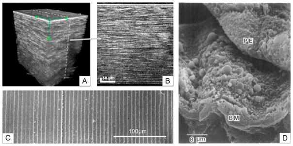
Anatomical and pathological motivations for topographically patterned biomaterial scaffolds. (A and B) Stacked images of the human cornea displaying the highly layered structure of microscale lamella within the stroma. (C) Scanning electron microscopy images of highly regular and parallel lens fiber cells positioned beneath the lens epithelium in rabbit. (D) Scanning electron micrograph of retinal pigment epithelium (PE) peeled from Bruch’s membrane (BM) revealing topographically intense drusen associated with age-related macular degeneration. (A) and (B) reprinted with permission from Latour G, Georges G, Lamoine LS, Beumie C, Conrath J, Hoffart L, J Biomed Opt, 2010, 15, 056996. (C) Reprinted from Kuszak JR, Zoltoski RK, Sivertson C, Exp Eye Res, 2004, 78, 673–87, with permission from Elsevier. (D) Republished with permission from Ulshafer RJ, Allen CB, Nicolaissen B Jr, Rubin ML, Invest Ophthalmol Vis Sci, 1987, 28.
Surface topography has been shown to be a major cue for CEC morphology. The most common topography studied has been ridge-groove patterns with varying feature depth and pitch. Pitch refers to the lateral distance between repeating units and is calculated as the ridge width plus groove width [33]. Most studies have found that CECs align parallel to both nanoscale and microscale repeating ridge-groove structures [31,98–100]. Teixeira and colleagues [31] cultured CECs on ridges and showed that cells align to features as small as 70nm wide with 400nm pitch. This was in stark contrast to CECs on unpatterned surfaces which were rounded (a potential indicator of poor health) and displayed no preference in orientation as shown in Figure 3. Other studies helped to identify the lower size limit for CEC topographical guidance of 20nm wide by 14nm deep by demonstrating that cells were unable to detect ridges with smaller dimensions [14,31,99]. Topography also affects cell adhesion as increasing groove depth or decreasing pitch results in improved attachment [31,38]. In addition, CECs migrate along the length of the grooves, a phenomenon that has been compared to the continual movement of limbal stem cell-derived CECs in vivo that maintain corneal homeostasis [101]. At the molecular level CEC alignment on grooved surfaces has been linked to Rho GTPases activation, an important mechanical and adhesion signaling pathway [14].
FIGURE 3.
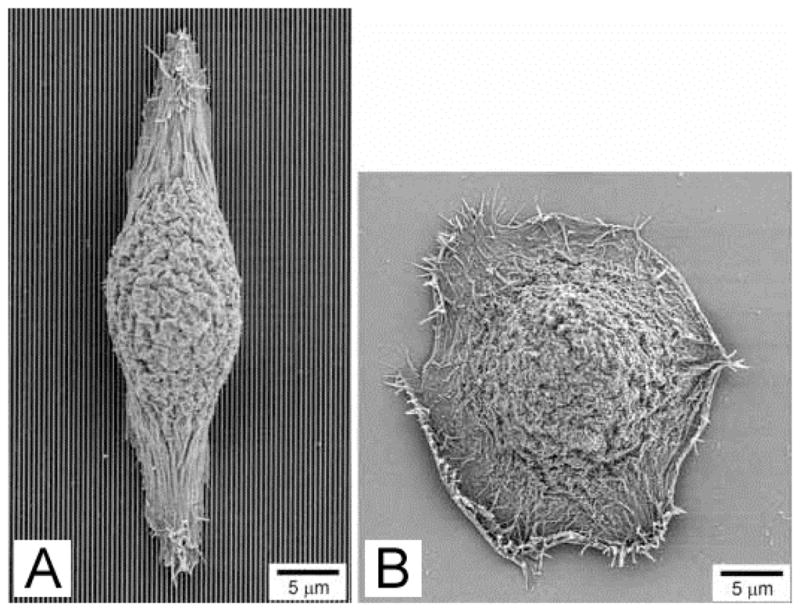
Human corneal epithelial cells align parallel to (A) 70 nm wide ridges with 400 nm pitch and 600 nm depth, but display no preferred orientation on (B) smooth surfaces. Reproduced with permission from Teixeira AI, Abrams GA, Bertics PJ, Murphy CJ, Nealey PF, J Cell Sci, 2003, 116, 1881–1892.
However, topography is not the only microenvironmental cue affecting CEC behavior, and other stimuli have also been studied. Teixeira and colleagues demonstrated that culture medium also plays a major role in CEC organization. Different media conditions were able to modulate the proportion and direction of aligned CECs which changed from parallel to perpendicular to the grooved features [31,100]. Other physiologically-relevant stimuli have also been tested in combination with topography. Karuri showed that the maximum percentage of CECs are retained on grooves with 400nm pitch when subjected to fluid-based shear stress that simulated the force encountered at the cornea due to blinking [38]. Rajnicek and colleagues used a DC electric field to simulate the persistent voltage difference in the cornea due to active ion transport and found that CECs align perpendicular to the electric field and migrate towards the cathode [14]. They further determined that the effects of an electrical field and topography could be combined to yield better alignment than either cue individually. Studies like this that address multiple, synergistic stimuli are especially critical for translational research as in vitro cell behavior is most physiologically relevant when conditions closely approximate the multi-factorial native microenvironment.
Keratocytes constitute a majority of the cells in the cornea and are a necessary component of full cornea tissue engineering. Unlike continually-renewing CECs, keratocytes only enter a proliferative state for the purposes of wound healing. However, keratocyte proliferation does not appear to be influenced by physical cues as cells on all topographies including a flat control expanded at similar rates [92]. As alluded to previously, one topography may have widely varying effects on different cell types. Consequently, nanoscale topography that results in superior CEC adhesion and alignment does not promote appropriate keratocyte behavior. Instead, keratocytes adhere and align better on grooves with microscale (2–4μm) compared to nanoscale (400nm) pitch or flat substrates [15]. A qualitative example of this improvement can be seen in Figure 4. Up to 70% of keratocytes aligned on microscale grooves compared to just 35% of CECs [15]. This fundamental difference in response to topography based on size may be attributed to the unique in vivo environments of each cell. Although both CECs and keratocytes experience fibers on the scale of 20–200nm, keratocytes also interact with multi-molecular lamellae that are 1 to 2.5μm thick which is one possible explanation for their superior response to microscale features [15].
FIGURE 4.
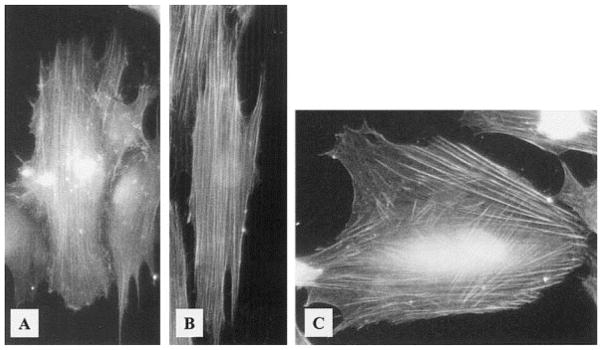
Stress fibers in human corneal epithelial cells align parallel to ridges with (A) 400 nm pitch (vertical) and (B) 4000 nm pitch (vertical), but are criss-crossed on (C) smooth substrates. Reprinted from Teixeira AI, Nealey PF, Murphy CJ, J Biomed Mater Res A 2004, 71, 369–76 with permission from Wiley-Blackwell.
In order to tissue engineer a full cornea, it may useful to employ multiple topographiesto meet the unique requirements of each cell type. Current studies and anatomical demands suggest that a thin, largely two-dimensional scaffold with ridge-groove nanotopography would be beneficial for the formation of a CEC monolayer [14,31,38,99], while a thicker, three-dimensional scaffold with microscale physical cues directing alignment would be ideal for keratocytes [15]. In addition, the scaffold would also have to be composed of a permeable material or incorporate pores to allow for metabolite transport [102].
Lens
The main function of the crystalline lens is to focus incident light on the retina. The refractive power of the lens is mostly provided by long, thin and transparent fiber cells derived from the lens epithelium [103]. Lens epithelial cells are the most active cell type in the lens and are responsible for both producing the ECM that constitutes the lens capsule and quiescent lens fiber cells [104]. Lens epithelial cells at the front of the lens proliferate and slowly migrate to the periphery where they undergo an epithelial-to-mesenchymal transition and terminally differentiate into lens fiber cells by elongating and losing a bulk of their contents [105–108]. This process results in concentric parallel layers of highly elongated fiber cells (Figure 2C) with hexagonal cross-section of approximately 7μm by 2μm [14,38,109]. In contrast to most epithelial basement membranes, the lens capsule is located outside of the lens epithelium. As a result, the apical side of the lens epithelium in direct contact with fiber cells which may play a role in regulating epithelial cell proliferation, migration, and/or differentiation [104,110].
Like the cornea, cell and ECM organization is critical for maintaining transparency of the lens [14,111]. Because fiber cells constitute a bulk of lens volume, they must be optically transparent to minimize interference with light traveling from an external source to the underlying retina. These cells achieve the required transparency by forming highly elongated fiber cells rich in crystallins, water-soluble proteins, and eliminating their organelles and nuclei that would otherwise scatter light [108]. While fiber cells are largely metabolically inactive after losing these components, their structural and optical properties are critical for proper lens function.
The most common source of lens opacification is cataracts which account for approximately 51% of all blindness [1]. Despite the lens’s capacity for self-repair, pathologies may exceed the amount of damage that can be naturally repaired and therefore necessitate intervention to fully restore function [105,112]. The current standard of care for lens injury is replacement with a transparent polymer. Though this procedure is well-established, complications such as reopacification may occur [113].
When cultured on flat surfaces, lens epithelial cells assume isotropic morphology resulting in an opaque, non-functional lens. Rajnicek and colleagues aimed to improve transparency by culturing lens epithelium on microgrooves to mimic native underlying fiber cell architecture and induce epithelial cell alignment [14,109]. Lens epithelial cells aligned parallel to nanoscale grooves when features were 130nm or deeper while shallower features did not induce significant cell alignment (Figure 5) suggesting lower sensitivity to physical cues than corneal epithelium discussed previously [14]. Because of the availability of alternative cell-free strategies for restoring lens function, lens epithelial cells are the least studied of the tissues discussed. Though drawing conclusions at this point in time would be premature, initial studies indicate that lens scaffolds with grooves or fibers on the order of native fiber dimensions (2–7μm) in cross-section may enhance lens epithelium proliferation and differentiation [14]. In this way it may be possible to create a cell-based engineered lens with regenerative capacity to prevent opacification.
FIGURE 5.

Bovine lens epithelial cells on various surfaces. (A) Graph displaying increasing alignment of cells with groove depth where an orientation index of 0 is randomly oriented and 21 is perfectly parallel alignment, ** indicates p<0.0001. Representative images of cells orientation on (B) a flat surface, (C) grooves 1 mm wide and 40 nm deep, and (D) grooves 2 mm wide and 320 nm deep. Scale bar indicates 50 mm. Reprinted from Rajnicek AM, Foubister LE, McCaig CD, Biomaterials, 2008, 29, 2082–2095, with permission from Elsevier.
Retina
The retina is composed of two regions: a neural inner region and outer region. Tissue engineering of the inner retina presently remains far from realization due to a poor understanding of complex neural networking. However, more is known about the cellular interaction and functional organization of the outer retina, namely photoreceptors and the retinal pigment epithelium (RPE). Photoreceptors are specialized rod or cone-shaped cells detect light and begin a biochemical cascade that ultimately produces vision [114]. These cells are maintained by the RPE, a confluent monolayer of pigmented cells that maintains favorable environmental conditions for photoreceptors and mediates metabolite transport to and from the underlying vasculature [115]. In vivo, photoreceptors are elongated cells that are aligned perpendicularly to the underlying RPE, an arrangement that is critical for proper function [116]. Columnar cell structure allows photoreceptors to pack densely in order to promote high resolution vision. As a byproduct of photon detection, waste is produced and secreted in membrane-bound outer segments at the posterior of the photoreceptor and subsequently phagocytosed by adjacent RPE [115].
Since photoreceptors and RPE are quiescent in the adult, regenerating these tissues will likely require a population of stem or precursor cells [117]. However, simple injections of cells has yielded poor survival, little engraftment, and no function [118,119]. Therefore, recent studies have focused on biomaterial scaffolds in order to enhance transplantation outcomes [120]. Several studies have explored the use of retinal progenitor cells in combination with topography for tissue engineering applications [61,121,122]. These cells, typically derived from fetal eyes, have the capacity to differentiate into multiple cell types including photoreceptors and RPE [123]. Because environmental factors such as orientation and paracrine cell signaling have been shown to play a critical role in retinal cell differentiation, topography may be able to induce progenitors differentiation towards a particular fate and/or into a physiologically-relevant structure [124–126].
Photoreceptors with normal morphology and outer segment formation are notoriously difficult to maintain in vitro for an extended period of time [127]. Long-term culture results in a loss of photoreceptor morphology and function in favor of fibroblastic markers. However this could be due in part to the vast environmental differences between their in vitro and native in vivo culture conditions [126]. Native photoreceptors are embedded in a three-dimensional matrix that is soft and in close proximity to RPE producing potent neurotrophic factors. In contrast, typical in vitro photoreceptor function is on two-dimensional, relatively stiff materials with no supporting cells.
Photoreceptors are likely to benefit from a scaffold to induce native-like organization as discussed in a review by Hynes and Lavik [128]. Multiple groups have aimed to address the problem of abnormal cell orientation using wells or pores to support columnar photoreceptor morphology [125,129]. Steedman and colleagues produced 25μm microwells and demonstrated increased retinal progenitor cell adhesion and an upregulation of photoreceptor-specific gene expression compared to flat materials [129]. Another group used a smaller, but similar pattern with 15μm wells (Figure 6A) that simulated the formation of progenitors clusters similar in size (15–20μm) and organization to whose observed during rodent retinal development [124,125]. This group observed that retinal progenitor cells seeded on this scaffold produced two laminated cell layers: one photoreceptor-like layer and another with gene expression profile indicative of ganglion and amacrine cells. Photoreceptors appeared to become polarized on these scaffolds and were best supported when co-cultured adjacent to an RPE/choroid explant (Figure 6B & 6C) [125]. In this study photoreceptors also exhibited 18-fold higher viability when cultured in low serum conditions at the gas-liquid interface compared to fully-submerged cultures in high serum.
FIGURE 6.
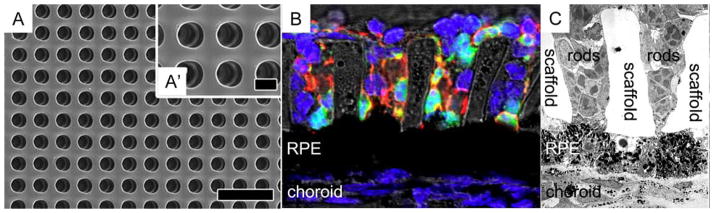
Microwell photoreceptor scaffold for supporting cell alignment perpendicular to the xy-plane. (A and A′) Scanning electron micrograph of the microchannel scaffold. (B) Immunohistochemical stain of photoreceptors (green = GFP+ rods, red = rhodopsin, and blue = nuclei) cultured on the scaffold above a subretinal mouse explant. (C) Transmission electron micrograph of photoreceptors on the scaffold cultured above explanted RPE. Scale bar in (A) and (A′) indicate 40 and 10 μm, respectively. Reprinted from McUsic AC, Lamba DA, Reh TA, Biomaterials, 2012, 33, 1396–1405, with permission from Elsevier. [Color figure can be viewed in the online issue, which is available at at wileyonlinelibrary.com.]
Taken together, these studies indicate that biomaterial supports have the ability to direct photoreceptor morphology and function [104,109]. For tissue engineering, the ideal photoreceptor scaffold would possess pores suitable for photoreceptor invasion and alignment in a densely-packed array [61,129–131]. Optimized in vitro conditions could also include cell proximity to the liquid-gas interface and co-culture with RPE. Despite improvements to in vitro photoreceptor culture, the prospect of retinal tissue engineering is severely limited by an inability to form synaptic connectivity between native and implanted cells of the neural retina. As a result, therapeutic transplantation of photoreceptors is likely to be a long-term endeavor.
Unlike photoreceptors, native RPE are well-spread, flat, and isotropic in the xy-plane. RPE adhere to Bruch’s membrane, a highly organized pentalaminar basement membrane composed of laminin, collagen, elastin, and fibronectin that separates these cells from the choriocapillaris, the vascular plexus nourishing the outer retina [132,133]. Scaffold-free therapies to transplant RPE have failed due to poor adhesion, improper polarization, and lack of long-term survival [134,135]. Instead, RPE are likely to benefit from a biomaterial substrate that can be delivered with the cells to promote proper cell organization [136]. Using this strategy, RPE would be cultured in vitro, form a monolayer, polarize, and be a fully-functioning mature tissue upon implantation. Due to Bruch’s membrane’s macroscopically flat topography, there have been numerous attempts to employ unpatterned biomaterials as substrates for RPE cell replacement, but these have encountered issues including a lack of sub-retinal biocompatibility and permeability issues [137–139]. Lim and colleagues showed that RPE behavior on a substrate with 5μm pillars lead to irregular RPE focal adhesions [140]. This is perhaps not surprising as microtopography is uncharacteristic of healthy Bruch’s membrane and reminiscent of pathological elements such as drusen. Drusen are lipoprotein deposits that form on or in Bruch’s membrane [141]. Imaging retinal cross-sections from AMD patients using transmission electron microscopy has associated RPE deformation around drusen with subsequent RPE death, so creating scaffolds with major topography is ill-advised [142]. An example of drusen morphology can be seen in Figure 2D.
Because other epithelial cell types such as CECs display improved morphology on nanotopography there is some rational for believing that smaller isotropic features could be beneficial [138]. Unfortunately, there have yet to be well-controlled studies of RPE on nanotopograpically patterned substrates, so no reliable conclusions can be drawn. Today most scaffolds being studied for RPE growth and delivery are thin and flat. In addition to flatness, RPE scaffolds must also be gas, liquid, and protein-permeable to support the intermediary function of RPE between the metabolically active photoreceptors and supplying vasculature [128,143]. Insufficient oxygen delivery or inadequate clearance of waste has been hypothesized to result in irregular cell function or death [144,145]. Yet permeable scaffolds must have pores sufficiently small to prevent both undesired changes to RPE morphology and vascular invasion [128]. Pores may have the same effect on cells as topography since they are geometrically the same as infinitely deep wells. Using small pores with well-defined size reduces the potential for RPE deformation into the pore and prevents trans-scaffold migration. Julien and coworkers demonstrated that polyimide foils with 1μm pores were biocompatible in the sub-retinal space of rats and capable of maintaining sufficient transport between the inner retina and vasculature to maintain homeostasis [146]. The results of these studies suggest that future scaffold-based RPE replacement strategies will require (1) appropriate substrate parameters including bulk material [147,148], surface treatment [138,140], and size [120,149]; (2) minimal topography; and (3) porosity/permeability for proper metabolite transport [143,150].
CONCLUSIONS
In the past, researchers have been limited to topographical patterning at the microscale; however, due to substantial technological advancements, topographical patterning with nanometer resolution has now become a reality [43,46–49,80]. Though the use of nanofabrication techniques is essential for cell types that require nanoscale topography, they are not necessarily the best choice for patterning microscale features due to practical concerns. Fabrication methods with decreasing minimum resolution are generally associated with increasing cost, so the optimal choice of patterning technique will likely possess sufficient, but not excessive resolution. As the topographies required range greatly between the nano- and microscale based on cell type, there is not one universally superior method for all applications. For example, wet etching or soft lithography may be appropriate for low aspect ratio microtopography, but is likely insufficiently resolute for cells that benefit from deep or complex nanotopography.
Although topographical cues alone are not able to fully mimic the in vivo cellular microenvironment, these cues have demonstrated utility for directing cell morphology, migration, gene expression, and function [10,35]. Artificial topographies that mimic the physical nature of a cell type’s native ECM frequently induce in vivo-like topography and function. Therefore, tissue engineers may be able to mimic the ECM architecture by leveraging existing fabrication technologies to create functional tissues for regenerative medicine [7,99].
Ocular cell types may be among the most likely to benefit from topographical cues [85]. The cornea and lens both rely on highly-regular organization of cells and ECM in order to maintain optical transparency and function. The use of parallel ridges to induce this alignment in engineered tissue is likely to increase bulk tissue transparency compared to cells cultured on flat surfaces [89,90]. In addition, photoreceptor orientation perpendicular to their plane is critical for high acuity vision and proper handling of outer segments [128,130,151]. These cells may benefit from a patterned scaffold of tightly-packed microwells to induce proper cell alignment and density which is unlikely to spontaneously arise on a planar biomaterial substrate [130].
Due to the vast number of combinations of microenvironmental variables, cell types, and potential surface topographies it can be difficult to identify the ideal topography for a particular cell type. However, studies regarding topography and ocular cells do show some consistency suggesting that epithelial cells may benefit more from nanotopography whereas mesenchymal cells are better regulated by microtopography [15]. From cell type-specific data it appears that CECs benefit from nanogrooves [31,38], keratocytes and lens epithelium/fiber cells from microgrooves [14,15], photoreceptors from microwells [125,129], and RPE from small pores with limited topography [140]. Future studies may look to build further upon these principles or aim to combine topography with other relevant stimuli in the native cellular microenvironment including soluble factors, forces, electrical potentials, and mechanical properties to develop tissue engineering strategies that are likely to succeed when translated to the in vivo setting.
References
- 1.Pascolini D, Mariotti SP. Global estimates of visual impairment: 2010. Br J Ophthalmol. 2012;96:614–618. doi: 10.1136/bjophthalmol-2011-300539. [DOI] [PubMed] [Google Scholar]
- 2.Resnikoff S, Keys TU. Future trends in global blindness. Indian J Ophthalmol. 2012;60:387–395. doi: 10.4103/0301-4738.100532. [DOI] [PMC free article] [PubMed] [Google Scholar]
- 3.Resnikoff SPD, Etya’ale D, Kocur I, Pararajasegaram R, Pokharel GP, Mariotti SP. Global data on visual impairment in the year 2002. Bull World Health Org. 2004;82:844–51. [PMC free article] [PubMed] [Google Scholar]
- 4.Stevens MM, George JH. Exploring and engineering the cell surface interface. Science. 2005;310:1135–1138. doi: 10.1126/science.1106587. [DOI] [PubMed] [Google Scholar]
- 5.Curtis ASG, Dalby M, Gadegaard N. Cell signaling arising from nanotopography: implications for nanomedical devices. Nanomedicine. 2006;1:67–72. doi: 10.2217/17435889.1.1.67. [DOI] [PubMed] [Google Scholar]
- 6.von der Mark K, Park J, Bauer S, Schmuki P. Nanoscale engineering of biomimetic surfaces: cues from the extracellular matrix. Cell Tissue Res. 2010;339:131–153. doi: 10.1007/s00441-009-0896-5. [DOI] [PubMed] [Google Scholar]
- 7.Abrams GA, Schaus SS, Goodman SL, Nealey PF, Murphy CJ. Nanoscale topography of the corneal epithelial basement membrane and Descemet’s membrane of the human. Cornea. 2000;19:57–64. doi: 10.1097/00003226-200001000-00012. [DOI] [PubMed] [Google Scholar]
- 8.Merker HJ. Morphology of the basement membrane. Microsc Res Tech. 1994;28:95–124. doi: 10.1002/jemt.1070280203. [DOI] [PubMed] [Google Scholar]
- 9.Chou L, Firth JD, Uitto VJ, Brunette DM. Substratum surface topography alters cell shape and regulates fibronectin mRNA level, mRNA stability, secretion and assembly in human fibroblasts. J Cell Sci. 1995;108:1563–1573. doi: 10.1242/jcs.108.4.1563. [DOI] [PubMed] [Google Scholar]
- 10.Yang Y, Leong KW. Nanoscale surfacing for regenerative medicine. Wiley Interdiscip Rev Nanomed Nanobiotechnol. 2010;2:478–495. doi: 10.1002/wnan.74. [DOI] [PubMed] [Google Scholar]
- 11.Britland S, Clark P, Connolly P, Moores G. Micropatterned substratum adhesiveness: a model for morphogenetic cues controlling cell behavior. Exp Cell Res. 1992;198:124–129. doi: 10.1016/0014-4827(92)90157-4. [DOI] [PubMed] [Google Scholar]
- 12.Folch A, Toner M. Microengineering of cellular interactions. Annu Rev Biomed Eng. 2000;2:227–256. doi: 10.1146/annurev.bioeng.2.1.227. [DOI] [PubMed] [Google Scholar]
- 13.Romano NH, Sengupta D, Chung C, Heilshorn SC. Protein-engineered biomaterials: nanoscale mimics of the extracellular matrix. Biochim Biophys Acta. 2011;1810:339–349. doi: 10.1016/j.bbagen.2010.07.005. [DOI] [PMC free article] [PubMed] [Google Scholar]
- 14.Rajnicek AM, Foubister LE, McCaig CD. Alignment of corneal and lens epithelial cells by co-operative effects of substratum topography and DC electric fields. Biomaterials. 2008;29:2082–2095. doi: 10.1016/j.biomaterials.2008.01.015. [DOI] [PubMed] [Google Scholar]
- 15.Teixeira AI, Nealey PF, Murphy CJ. Responses of human keratocytes to micro- and nanostructured substrates. J Biomed Mater Res A. 2004;71:369–376. doi: 10.1002/jbm.a.30089. [DOI] [PubMed] [Google Scholar]
- 16.Clark P, Connolly P, Curtis ASG, Dow JAT, Wilkinson CDW. Topographical control of cell behavior II. multiple grooved substrata. Development. 1990;108:635–644. doi: 10.1242/dev.108.4.635. [DOI] [PubMed] [Google Scholar]
- 17.Rosenberg MD. Long-range interactions between cell and substratum. Proc Natl Acad Sci. 1962;48:1342–1349. doi: 10.1073/pnas.48.8.1342. [DOI] [PMC free article] [PubMed] [Google Scholar]
- 18.Rosenberg MD. Cell guidance by alterations in monomolecular films. Science. 1963;139:211–212. doi: 10.1126/science.139.3553.411. [DOI] [PubMed] [Google Scholar]
- 19.Trinkaus-Randall VCJ, Newton A, Vadasz A, Leibowitz HM, Franzblau C. Development of a biopolymeric keratoprosthesis material: evaluation in vitro and in vivo. Invest Ophthalmol Vis Sci. 1988;29:293–300. [PubMed] [Google Scholar]
- 20.Dalby MJ, Riehle MO, Johnstone JH, Affrossman S, Curtis ASG. Polymer-demixed nanotopography: control of fibroblast spreading and proliferation. Tissue Eng. 2002;8:1099–1107. doi: 10.1089/107632702320934191. [DOI] [PubMed] [Google Scholar]
- 21.Dalby MJ, Riehle MO, Johnstone H, Affrossman S, Curtis ASG. In vitro reaction of endothelial cells to polymer demixed nanotopography. Biomaterials. 2002;23:927–935. doi: 10.1016/s0142-9612(01)00424-0. [DOI] [PubMed] [Google Scholar]
- 22.Friedl P, Zaenker KS, Broecker EB. Cell migration strategies in 3-D extracellular matrix: differences in morphology, cell matrix interactions, and integrin function. Microsc Res Tech. 1998;45:369–378. doi: 10.1002/(SICI)1097-0029(19981201)43:5<369::AID-JEMT3>3.0.CO;2-6. [DOI] [PubMed] [Google Scholar]
- 23.Carnegie JA, Cabaca O. Extracellular matrix composition and resilience: two parameters that influence the in vitro migration and morphology of rat inner cell mass-derived cells. Biol Reprod. 1993;48:287–299. doi: 10.1095/biolreprod48.2.287. [DOI] [PubMed] [Google Scholar]
- 24.Watanabe K, Nakagawa S, Nishida T. Stimulatory effects on fibronectin and EGF on migration of corneal epithelial cells. Invest Ophthalmol Vis Sci. 1987;28:205–211. [PubMed] [Google Scholar]
- 25.Watanabe K, Nakagawa S, Nishida T. Chemotactic and haptotactic activities of fibronectin for cultured rabbit corneal epithelial cells. Invest Ophthalmol Vis Sci. 1988;29:572–577. [PubMed] [Google Scholar]
- 26.Reid TW. Growth control of cornea and lens epithelial cells. Prog Retinal Eye Res. 1994;13:507–554. [Google Scholar]
- 27.Dalby MJ, Gadegaard N, Tare R, Andar A, Riehle MO, Herzyk P, Wilkinson CDW, Oreffo ROC. The control of human mesenchymal cell differentiation using nanoscale symmetry and disorder. Nat Mater. 2007;6:997–1003. doi: 10.1038/nmat2013. [DOI] [PubMed] [Google Scholar]
- 28.Popat KC, Chatvanichkul KI, Barnes GL, Latempa TJ, Grimes CA, Desai TA. Osteogenic differentiation of marrow stromal cells cultured on nanoporous alumina surfaces. J Biomed Mater Res A. 2007;80:955–964. doi: 10.1002/jbm.a.31028. [DOI] [PubMed] [Google Scholar]
- 29.Chiquet M, Matthisson M, Koch M, Tannheimer M, Chiquet-Ehrismann R. Regulation of extracellular matrix synthesis by mechanical stress. Biochem Cell Biol. 1996;74:737–744. doi: 10.1139/o96-080. [DOI] [PubMed] [Google Scholar]
- 30.Andersson AS, Bäckhed F, Von Euler A, Richter-Dahlfors A, Sutherland D, Kasemo B. Nanoscale features influence epithelial cell morphology and cytokine production. Biomat. 2003;24:3427–3436. doi: 10.1016/s0142-9612(03)00208-4. [DOI] [PubMed] [Google Scholar]
- 31.Teixeira AI, Abrams GA, Bertics PJ, Murphy CJ, Nealy PF. Epithelial contact guidance on well-defined micro- and nanostructured substrates. J Cell Sci. 2003;116:1881–1892. doi: 10.1242/jcs.00383. [DOI] [PMC free article] [PubMed] [Google Scholar]
- 32.Flemming RG, Murphy CJ, Abrams GA, Goodman SL, Nealy PF. Effects of synthetic micro- and nano-structured surfaces on cell behavior. Biomaterials. 1999;20:573–588. doi: 10.1016/s0142-9612(98)00209-9. [DOI] [PubMed] [Google Scholar]
- 33.Raghunathan VK, McKee CT, Tocce EJ, Nealey PF, Russel P, Murphy CJ. Nuclear and cellular alignment of primary corneal epithelial cells on topography. J Biomed Mater Res A. 2012 doi: 10.10002/jbm.a.34417. Epub on Sep 11, 2012. [DOI] [PMC free article] [PubMed] [Google Scholar]
- 34.Abrams G, Teixeira A, Nealy P, Murphy C. The effects of substratum topography on cell behavior. In: Dillow A, Lowman A, editors. Biomimetic Materials and Design: Interactive Biointerfacial Strategies, Tissue Engineering, and Drug Delivery. New York: Marcel Dekker; 2002. pp. 91–136. [Google Scholar]
- 35.Curtis A. Tutorial on the biology of nanotopography. IEEE Trans Nanobioscience. 2004;3:293–295. doi: 10.1109/tnb.2004.837898. [DOI] [PubMed] [Google Scholar]
- 36.Curtis ASG, Casey B, Gallagher JO, Pasqui D, Wood MA, Wilkinson CD. Substratum nanotopography of biological cells. Are symmetry or regularity of nanotopography important? Biophys Chem. 2001;94:275–283. doi: 10.1016/s0301-4622(01)00247-2. [DOI] [PubMed] [Google Scholar]
- 37.Ohara PT, Buck RC. Contact guidance in vitro: a light, transmission, and scanning electron microscopic study. Exp Cell Res. 1979;121:235–249. doi: 10.1016/0014-4827(79)90002-8. [DOI] [PubMed] [Google Scholar]
- 38.Karuri NW, Liliensiek S, Teixeira AI, Abrams G, Campbell S, Nealy PF, Murphy CJ. Biological length scale topography enhances cell-substratum adhesion of human corneal epithelial cells. J Cell Sci. 2004;117:3153–3164. doi: 10.1242/jcs.01146. [DOI] [PMC free article] [PubMed] [Google Scholar]
- 39.Birk DE, Trelstad RL. Extracellular compartments in matrix morphogenesis; collagen fibril, bundle, and lamellar formation by corneal fibroblasts. J Cell Biol. 1984;99:2024–2033. doi: 10.1083/jcb.99.6.2024. [DOI] [PMC free article] [PubMed] [Google Scholar]
- 40.den Braber ET, de Ruigter JE, Ginsel LA, von Recum AF, Jansen JA. Orientation of ECM protein deposition, fibroblast cytoskeleton, and attachment complex components on silicone microgrooved surfaces. J Biomed Mater Res. 1998;40:291–300. doi: 10.1002/(sici)1097-4636(199805)40:2<291::aid-jbm14>3.0.co;2-p. [DOI] [PubMed] [Google Scholar]
- 41.Curtis ASG, Gadegaard N, Dalby MJ, Riehle MO, Wilikison CD, Aitchison G. Cells react to nanoscale order and symmetry in their surroundings. IEEE Trans Nanobioscience. 2004;3:61–65. doi: 10.1109/tnb.2004.824276. [DOI] [PubMed] [Google Scholar]
- 42.Deok-Ho K, Levchenko A, Suh KY. Engineered surface nanotopography for controlling cell-substrate interactions. In: Khademhosseini A, Borenstein J, Toner M, Takayama S, editors. Micro and Nanoengineering of the Cell Microenvironment: Technologies and Applications. Norwood, MA: Artech House Publishers; 2008. pp. 185–208. [Google Scholar]
- 43.Chen Y, Pépin A. Nanofabrication: conventional and nonconventional methods. Electrophoresis. 2001;22:187–207. doi: 10.1002/1522-2683(200101)22:2<187::AID-ELPS187>3.0.CO;2-0. [DOI] [PubMed] [Google Scholar]
- 44.Muray A, Scheinfein M, Isaacson M, Adesida I. Radiolysis and resolution limits of inorganic halide resists. J Vac Sci Technol. 1985;B3:367–372. [Google Scholar]
- 45.Madou MJ. Fundamentals of Microfabrication. Boca Raton, FL: CRC Press; 1997. [Google Scholar]
- 46.Chien FSS, Wu CL, Chou YC, Chen TT, Gwo S. Nanomachining of (110)-oriented silicon by scanning probe lithography and anisotropic wet etching. Appl Phys Lett. 1999;75:2429–2431. [Google Scholar]
- 47.Chen KS, Ayon AA, Zhang X, Spearing SM. Effect of process parameters on the surface morphology and mechanical performance of silicon structures after deep reactive ion etching (DRIE) J MEMS. 2002;11:264–275. [Google Scholar]
- 48.Khraiche ML, Lo Y, Wang D, Cauwenberghs G, Freeman W, Silva GA. Ultra-high photosensitivity silicon nanophotonics for retinal prosthesis: electrical characteristics. Conf Proc IEEE Eng Med Biol Soc. 2011;2011:2933–2936. doi: 10.1109/IEMBS.2011.6090807. [DOI] [PubMed] [Google Scholar]
- 49.Marty F, Rousseau L, Saadany B, Mercier B, Français O, Mita Y, Bourouina T. Advanced etching of silicon based on deep reactive ion etching for silicon high aspect ratio microstructures and three-dimensional micro- and nanostructures. Microelectr J. 2005;36:673–677. [Google Scholar]
- 50.Qin D, Xia Y, Whitesides GM. Soft lithography for micro- and nanoscale patterning. Nat Protoc. 2010;5:491–502. doi: 10.1038/nprot.2009.234. [DOI] [PubMed] [Google Scholar]
- 51.Weibel DB, DiLuzio WR, Whitesides GM. Microfabrication meets microbiology. Nat Rev Micro. 2007;5:209–218. doi: 10.1038/nrmicro1616. [DOI] [PubMed] [Google Scholar]
- 52.Nikkhah M, Edalat F, Manoucheri S, Khademhosseini A. Engineering microscale topographies to control the cell-substrate interface. Biomaterials. 2012;33:5230–5246. doi: 10.1016/j.biomaterials.2012.03.079. [DOI] [PMC free article] [PubMed] [Google Scholar]
- 53.Suh KY, Lee HH. Capillary force lithography: large-area patterning, self-organization, and anisotropic dewetting. Adv Funct Mater. 2002;12:405–413. [Google Scholar]
- 54.Delamarche E, Schmid H, Michel B, Biebuyck H. Stability of molded polydimethylsiloxane microstructures. Adv Mater. 1997;9:741–746. [Google Scholar]
- 55.Vozzi G, Flaim C, Ahluwalia A, Bhatia S. Fabrication of PLGA scaffolds using soft lithography and microsyringe deposition. Biomaterials. 2003;24:2533–2540. doi: 10.1016/s0142-9612(03)00052-8. [DOI] [PubMed] [Google Scholar]
- 56.Jackman RJ, Duffy DC, Cherniavskaya O, Whitesides GM. Using elastomeric membranes as dry resists and for dry liftoff. Langmuir. 1999;15:2973–2984. [Google Scholar]
- 57.Xie Y, Jiang X. Microcontact Printing. Methods Mol Biol. 2011;671:239–248. doi: 10.1007/978-1-59745-551-0_14. [DOI] [PubMed] [Google Scholar]
- 58.McDonald JC, Duffy DC, Anderson JR, Chiu DT, Wu H, Schueller OJ, Whitesides GM. Fabrication of microfluidic systems in poly(dimethylsiloxane) Electrophoresis. 2000;21:27–40. doi: 10.1002/(SICI)1522-2683(20000101)21:1<27::AID-ELPS27>3.0.CO;2-C. [DOI] [PubMed] [Google Scholar]
- 59.Chou SY, Krauss PR, Zhang W, Guo L, Zhuang L. Sub-10 nm imprint lithography and applications. J Vacuum Sci Tech B. 1997;15:2897–2904. [Google Scholar]
- 60.Tiaw KS, Teoh SH, Chen R, Hong MH. Processing methods of ultrathin poly(epsilon-caprolactone) films for tissue engineering applications. Biomacromolecules. 2007;8:807–816. doi: 10.1021/bm060832a. [DOI] [PubMed] [Google Scholar]
- 61.Sodha S, Wall K, Redenti S, Klassen H, Young MJ, Tao SL. Microfabrication of a three-dimensional polycaprolactone thin-film scaffold for retinal progenitor cell encapsulation. J Biomater Sci Polym Ed. 2011;22:443–456. doi: 10.1163/092050610X487738. [DOI] [PubMed] [Google Scholar]
- 62.Stroscio JA, Eigler DM. Atomic and molecular manipulation with the scanning tunneling microscope. Science. 1991;29:1319–1326. doi: 10.1126/science.254.5036.1319. [DOI] [PubMed] [Google Scholar]
- 63.Salaita K, Wang Y, Fragala J, Vega RA, Liu C, Mirkin CA. Massively parallel dip-pen nanolithography with 55000-pen two-dimensional arrays. Angew Chem Int Ed. 2006;45:7220–7223. doi: 10.1002/anie.200603142. [DOI] [PubMed] [Google Scholar]
- 64.Foster JS, Frommer JE, Arnett PC. Molecular manipulation using a tunnelling microscope. Nature. 1988;331:324–326. doi: 10.1038/331324a0. [DOI] [PubMed] [Google Scholar]
- 65.Eigler DM, Schweizer EK. Positioning single atoms with a scanning tunnelling microscope. Nature. 1990;344:524–526. [Google Scholar]
- 66.Crommie MF, Lutz CP, Eigler M. Confinement of electrons to quantum corrals on a metal surface. Science. 1993;262:218–220. doi: 10.1126/science.262.5131.218. [DOI] [PubMed] [Google Scholar]
- 67.Tseng AA, Notargiacomo A. Nanoscale fabrication by nonconventional approaches. J Nanosci Nanotechnol. 2005;5:683–702. doi: 10.1166/jnn.2005.116. [DOI] [PubMed] [Google Scholar]
- 68.de Gans BJ, Duineveld PC, Schubert US. Inkjet printing of polymers: state of the art and future developments. Adv Mater. 2004;16:203–13. [Google Scholar]
- 69.Boland T, Xu T, Damon B, Cui X. Application of inkjet printing to tissue engineering. Biotechnol J. 2006;1:910–7. doi: 10.1002/biot.200600081. [DOI] [PubMed] [Google Scholar]
- 70.Zhang Y, Tse C, Rouholamin D, Smith PJ. Scaffolds for tissue engineering produced by inkjet printing. Cent Eur J Eng. 2012;2:325–35. [Google Scholar]
- 71.Derby B. Inkjet printing of functional and structural materials: fluid property requirements, feature stability, and resolution. Annu Rev Mater Res. 2010;40:395–414. [Google Scholar]
- 72.Sirringhaus H, Kawase T, Friend RH, Shimoda T, Inbasekaran M, Wu W, Woo EP. High-resolution inkjet printing of all-polymer transistor circuits. Science. 2000;290:2123–6. doi: 10.1126/science.290.5499.2123. [DOI] [PubMed] [Google Scholar]
- 73.Arnold CB, Serra P, Piqué A. Laser direct-write techniques for printing of complex materials. MRS Bull. 2007;32:23–31. [Google Scholar]
- 74.Gratson GM, Xu M, Lewis JA. Microperiodic structures: direct writing of three-dimensional webs. Nature. 2004;428:386. doi: 10.1038/428386a. [DOI] [PubMed] [Google Scholar]
- 75.Banks DP, Grivas C, Mills JD, Zergioti I, Eason RW. Nanodroplets deposited in microarrays by femtosecond TI:sapphire laser-induced forward transfer. Appl Phys Lett. 2006;89:193107. [Google Scholar]
- 76.Fitz-Gerald JM, Wu DH, Pique A, Horwitz JS, Auyeung RCY, Chang W, Kim WJ, Chrisey DB. Maple direct write: a new approach to fabricate ferroelectric thin film devices in air at room temperature. Integr Ferroelectr. 2000;28:13–28. [Google Scholar]
- 77.Lewis JA, Gratson GM. Direct writing in three dimensions. Materials Today. 2004:32–39. [Google Scholar]
- 78.Kancharla VV, Chen S. Fabrication of biodegradable polymeric micro-devices using laser micromachining. Biomed Microdevices. 2002;4:105–9. [Google Scholar]
- 79.Aguilar CA, Lu Y, Mao S, Chen S. Direct micro-patterning of biodegradable polymers using ultraviolet and femtosecond lasers. Biomaterials. 2005;26:7642–9. doi: 10.1016/j.biomaterials.2005.04.053. [DOI] [PubMed] [Google Scholar]
- 80.Raimondi MT, Eaton SM, Nava MM, Laganà M, Cerullo G, Osellame R. Two-photon laser polymerization: from fundamentals to biomedical application in tissue engineering and regenerative medicine. J Appl Biomater Biomech. 2012;10:55–65. doi: 10.5301/JABFM.2012.9278. [DOI] [PubMed] [Google Scholar]
- 81.Cumpston BH, Ananthavel SP, Barlow S, Dyer DL, Ehrlich JE, Erskine LL, Heikal AA, Kuebler SM, Sandy Lee IY, McCord-Maughon D, Qin J, Röckel H, Rumi M, Wu XL, Marder SR, Perry JW. Nature. 1999;398:51–4. [Google Scholar]
- 82.Ovsianikov A, Chichkov BN. Three-dimensional microfabrication by two-photon polymerization technique. In: Liebschner MAK, editor. Computer-Aided Tissue Engineering. New York: Springer; 2012. pp. 311–326. [DOI] [PubMed] [Google Scholar]
- 83.Torgersen J, Ovsianikov A, Mironov V, Pucher N, Qin X, Li Z, Cicha K, Machacek T, Liska R, Jantsch V, Stampfl J. Photo-sensitive hydrogels for three-dimensional laser microfabrication in the presence of whole organisms. J Biomed Opt. 2012;17:105008. doi: 10.1117/1.JBO.17.10.105008. [DOI] [PubMed] [Google Scholar]
- 84.Gittard SD, Koroleva A, Nguyen AK, Fadeeva E, Gaidukeviciute A, Schile-Wolter S, Narayan RJ, Chichkov B. Two-photon polymerization microstructuring in regenerative medicine. Front Biosci (Elite Ed) 2013;5:602–9. doi: 10.2741/e642. [DOI] [PubMed] [Google Scholar]
- 85.Boulton M, Albon J. Stem cells in the eye. Int J Biochem Cell Biol. 2004;36:643–657. doi: 10.1016/j.biocel.2003.10.013. [DOI] [PubMed] [Google Scholar]
- 86.Redenti S, Neeley WL, Rompani S, Saigal S, Yang J, Klassen H, Langer R, Young MJ. Engineering retinal progenitor cell and scrollable poly(glycerol-sebacate) composites for expansion and subretinal transplantation. Biomaterials. 2009;30:3405–3414. doi: 10.1016/j.biomaterials.2009.02.046. [DOI] [PMC free article] [PubMed] [Google Scholar]
- 87.Lazzaro DR. What’s new in ophthalmic surgery. J Am Coll Surg. 2005;200:96–102. doi: 10.1016/j.jamcollsurg.2004.09.038. [DOI] [PubMed] [Google Scholar]
- 88.Schwartz SD, Hubschman JP, Heilwell G, Franco-Cardenas V, Pan CK, Ostrick RM, et al. Embryonic stem cell trials for macular degeneration: a preliminary report. Lancet. 2012;379:713–720. doi: 10.1016/S0140-6736(12)60028-2. [DOI] [PubMed] [Google Scholar]
- 89.Yang J, Yamato M, Nishida K, Ohki T, Kanzaki M, Sekine H, Shimizu T, Okano T. Cell delivery in regenerative medicine: the cell sheet engineering approach. J Control Release. 2006;116:193–203. doi: 10.1016/j.jconrel.2006.06.022. [DOI] [PubMed] [Google Scholar]
- 90.Nakamura K, Kurosaka D, Bissen-Miyajima H, Tsubota K. Intact corneal epithelium is essential for the prevention of stromal haze after laser assisted in situ keratomileusis. Br J Ophthalmol. 2001;85:209–213. doi: 10.1136/bjo.85.2.209. [DOI] [PMC free article] [PubMed] [Google Scholar]
- 91.Ambekar R, Toussant KC, Johnson AW. The effect of keratconus on the structural, mechanical, and optical properties of the cornea. J Mech Behav Biomed Mater. 2011;4:223–236. doi: 10.1016/j.jmbbm.2010.09.014. [DOI] [PubMed] [Google Scholar]
- 92.Liliensiek SJ, Campbell S, Nealy PF, Murphy CJ. The scale of substratum topographic features modulates proliferation of corneal epithelial cells and corneal fibroblasts. J Biomed Mater Res A. 2006;79:185–192. doi: 10.1002/jbm.a.30744. [DOI] [PMC free article] [PubMed] [Google Scholar]
- 93.Knupp C, Pinali C, Lewis PN, Parfitt GJ, Young RD, Meek KM, Quantock AJ. The architecture of the cornea and structural basis of its transparency. Adv Protein Chem Struct Biol. 2009;78:25–49. doi: 10.1016/S1876-1623(08)78002-7. [DOI] [PubMed] [Google Scholar]
- 94.Majo F, Rochat A, Nicolas M, Jaoudé GA, Barrandon Y. Oligopotent stem cells are distributed throughout the mammalian ocular surface. Nature. 2008;456:250–254. doi: 10.1038/nature07406. [DOI] [PubMed] [Google Scholar]
- 95.Nishida T, Yasumoto K, Otori T, Desaki J. The network structure of corneal fibroblasts in the rat as revealed by scanning electron-microscopy. Invest Ophthalmol Vis Sci. 1988;29:1887–1890. [PubMed] [Google Scholar]
- 96.Snyder MC, Bergmanson JP, Doughty MJ. Keratocytes: no more thequiet cells. J Am Optom Assoc. 1998;69:180–187. [PubMed] [Google Scholar]
- 97.Worthington CR. The structure of cornea. Q Rev Biophys. 1984;17:423–451. doi: 10.1017/s003358350000487x. [DOI] [PubMed] [Google Scholar]
- 98.Karuri NW, Nealy PF, Murphy CJ, Albrecht RM. Structural organization of the cytoskeleton in SV40 human corneal epithelial cells cultured on nano- and microscale grooves. Scanning. 2008;30:405–413. doi: 10.1002/sca.20123. [DOI] [PMC free article] [PubMed] [Google Scholar]
- 99.Tocce EJ, Smirnov VK, Kibalov DS, Liliensiek SJ, Murphy CJ, Nealy PF. The ability of corneal epithelial cells to recognize high aspect ratio nanostructures. Biomaterials. 2010;31:4064–4072. doi: 10.1016/j.biomaterials.2010.01.101. [DOI] [PMC free article] [PubMed] [Google Scholar]
- 100.Teixeira AI, McKie GA, Foley JD, Bertics PJ, Nealy PF, Murphy CJ. The effect of environmental factors on the response of human corneal epithelial cells to nanoscale substrate topography. Biomaterials. 2006;27:3945–3954. doi: 10.1016/j.biomaterials.2006.01.044. [DOI] [PMC free article] [PubMed] [Google Scholar]
- 101.Diehl KA, Foley JD, Nealy PF, Murphy CJ. Nanoscale topography modulates corneal epithelial cell migration. J Biomed Mater Res A. 2005;75:603–611. doi: 10.1002/jbm.a.30467. [DOI] [PubMed] [Google Scholar]
- 102.Cai H, Howells RD, Wagner BJ. Identification of a novel gene product preferentially expressed in rat lens epithelial cells. Mol Vis. 1999;5:3. [PubMed] [Google Scholar]
- 103.Smith G, Pierscionek BK. The optical structure of the lens and its contribution to the refractive status of the eye. Ophthalmic Physiol Opt. 1998;18:21–29. [PubMed] [Google Scholar]
- 104.Martinez G, de Iongh RU. The lens epithelium in ocular health and disease. Int J Biochem Cell Biol. 2010;42:1945–1963. doi: 10.1016/j.biocel.2010.09.012. [DOI] [PubMed] [Google Scholar]
- 105.Wederell ED, de Iongh Extracellular matrix and integrin signaling in lens development and cataract. Semin Cell Dev Biol. 2006;17:759–776. doi: 10.1016/j.semcdb.2006.10.006. [DOI] [PubMed] [Google Scholar]
- 106.Walker J, Menok AS. Integrins in lens development and disease. Exp Eye Res. 2009;88:216–225. doi: 10.1016/j.exer.2008.06.020. [DOI] [PMC free article] [PubMed] [Google Scholar]
- 107.Kuszak JR, Zoltoski RK, Sivertson C. Fibre cell organization in crystalline lenses. Exp Eye Res. 2004;78:673–687. doi: 10.1016/j.exer.2003.09.016. [DOI] [PubMed] [Google Scholar]
- 108.Wride MA. Minireview: apoptosis as seen through a lens. Apoptosis. 2000;5:203–209. doi: 10.1023/a:1009653326511. [DOI] [PubMed] [Google Scholar]
- 109.Kuszak J, Alcala J, Maisel H. The surface morphology of embryonic and adult chick lens-fiber cells. Am J Anat. 1980;159:395–410. doi: 10.1002/aja.1001590406. [DOI] [PubMed] [Google Scholar]
- 110.Bassnett S, Kuszak JR, Reinisch L, Brown HG, Beebe DC. Intercellular communication between epithelial and fiber cells of the eye lens. J Cell Sci. 1994;107:799–811. doi: 10.1242/jcs.107.4.799. [DOI] [PubMed] [Google Scholar]
- 111.Truscott RJW, Zhu X. Presbyopia and cataract: A question of heat and time. Prog Retin Eye Res. 2010;29:487–499. doi: 10.1016/j.preteyeres.2010.05.002. [DOI] [PubMed] [Google Scholar]
- 112.Trivedi RH, Werner L, Apple DJ, Pandey SK, Izak AM. Post cataract-intraocular lens (IOL) surgery opacification. Eye (Lond) 2002;16:217–241. doi: 10.1038/sj.eye.6700066. [DOI] [PubMed] [Google Scholar]
- 113.Evans MD, Taylor S, Dalton A, Lohmann D. Polymer design for corneal epithelial tissue adhesion: pore density. J Biomed Mater Res A. 2003;64:357–364. doi: 10.1002/jbm.a.10341. [DOI] [PubMed] [Google Scholar]
- 114.Magalit E, Sadda SR. Retinal and optic nerve diseases. Artif Organs. 2003;27:983–974. doi: 10.1046/j.1525-1594.2003.07304.x. [DOI] [PubMed] [Google Scholar]
- 115.Strauss O. The retinal pigment epithelium in visual function. Physiol Rev. 2005;85:845–881. doi: 10.1152/physrev.00021.2004. [DOI] [PubMed] [Google Scholar]
- 116.Silverman MS, Hughes SE. Photoreceptor transplantation in inherited and environmentally induced retinal degeneration: anatomy, immunohistochemistry and function. Prog Clin Biol Res. 1989;314:687–704. [PubMed] [Google Scholar]
- 117.Ong JM, da Cruz L. A review and update on the current status of stem cell therapy and the retina. Br Med Bull. 2012;102:133–146. doi: 10.1093/bmb/lds013. [DOI] [PubMed] [Google Scholar]
- 118.Tezel TH, Del Priore LV. Reattachment to a substrate prevents apoptosis of human retinal pigment epithelium. Graefes Arch Clin Exp Ophthalmol. 1997;235:41–7. doi: 10.1007/BF01007836. [DOI] [PubMed] [Google Scholar]
- 119.Li L, Turner JE. Optimal conditions for long-term photoreceptor cell rescue in RCS rats: the necessity for healthy RPE transplants. Exp Eye Res. 1991;52:669–79. doi: 10.1016/0014-4835(91)90019-b. [DOI] [PubMed] [Google Scholar]
- 120.Tomita M, Lavik E, Klassen H, Zahir T, Langer R, Young MJ. Biodegradable polymer composite grafts promote the survival and differentiation of retinal progenitor cells. Stem Cells. 2005;23:1579–88. doi: 10.1634/stemcells.2005-0111. [DOI] [PubMed] [Google Scholar]
- 121.Tao S, Young C, Redenti S, Zhang Y, Klassen H, Desai T, Young MJ. Survival, migration and differentiation of retinal progenitor cells transplanted on micro-machined poly(methyl methacrylate scaffolds to the subretinal space. Lab Chip. 2007;7:695–701. doi: 10.1039/b618583e. [DOI] [PubMed] [Google Scholar]
- 122.Neeley WL, Redenti S, Klassen H, Tao S, Desai T, Young MJ, Langer R. A microfabricated scaffold for retinal progenitor cell grafting. Biomaterials. 2008;29:418–426. doi: 10.1016/j.biomaterials.2007.10.007. [DOI] [PMC free article] [PubMed] [Google Scholar]
- 123.Gong J, Sagiv O, Cai H, Tsang SH, Del Priore LV. Effects of extracellular matrix and neighboring cells on induction of human embryonic stem cells into retinal or retinal pigment epithelial progenitors. Exp Eye Res. 2008;86:957–965. doi: 10.1016/j.exer.2008.03.014. [DOI] [PMC free article] [PubMed] [Google Scholar]
- 124.Turner DL, Snyder EY, Cepko CL. Lineage-independent determination of cell type in the embryonic mouse retina. Neuron. 1990;4:833–845. doi: 10.1016/0896-6273(90)90136-4. [DOI] [PubMed] [Google Scholar]
- 125.McUsic AC, Lamba DA, Reh TA. Guiding the morphogenesis of dissociated newborn mouse retinal cells and hES cell-derived retinal cells by soft lithography-patterned microchannel PLGA scaffolds. Biomaterials. 2012;33:1396–1405. doi: 10.1016/j.biomaterials.2011.10.083. [DOI] [PMC free article] [PubMed] [Google Scholar]
- 126.Sheedlo HJ, Bartosh TJ, Wang Z, Srinivasan B, Brun-Zinkernagel AM, Roque RS. RPE-derived factors modulate photoreceptor differentiation: a possible role in the retinal stem cell niche. In Vitro Cell Dev Biol Anim. 2007;43:361–370. doi: 10.1007/s11626-007-9051-3. [DOI] [PubMed] [Google Scholar]
- 127.Ogilvie JM, Speck JD, Lett JM, Fleming TT. A reliable method for organ culture of neonatal mouse retina with long-term survival. J Neurosci Methods. 1999;87:57–65. doi: 10.1016/s0165-0270(98)00157-5. [DOI] [PubMed] [Google Scholar]
- 128.Hynes SR, Lavik EB. A tissue-engineered approach towards retinal repair: scaffolds for cell transplantation to the subretinal space. Graefes Arch Clin Exp Ophthalmol. 2010;248:763–778. doi: 10.1007/s00417-009-1263-7. [DOI] [PubMed] [Google Scholar]
- 129.Steedman MR, Tao SL, Klassen H, Desai TA. Enhanced differentiation of retinal progenitor cells using microfabricated topographical cues. Biomed Microdevices. 2010;12:363–369. doi: 10.1007/s10544-009-9392-7. [DOI] [PMC free article] [PubMed] [Google Scholar]
- 130.Lavik EB, Klassen H, Warfvinge K, Langer R, Young MJ. Fabrication of degradable polymer scaffolds to direct the integration and differentiation of retinal progenitors. Biomaterials. 2005;26:3187–96. doi: 10.1016/j.biomaterials.2004.08.022. [DOI] [PubMed] [Google Scholar]
- 131.Tao S, Young C, Redenti S, Zhang Y, Klassen H, Desai T, Young MJ. Survival, migration and differentiation of retinal progenitor cells transplanted on micro-machined poly(methyl methacrylate) scaffolds to the subretinal space. Lab Chip. 2007;7:695–701. doi: 10.1039/b618583e. [DOI] [PubMed] [Google Scholar]
- 132.Sheridan C, Williams R, Grierson I. Basement membranes and artificial substrates in cell transplantation. Graefes Arch Clin Exp Ophthalmol. 2004;242:68–75. doi: 10.1007/s00417-003-0800-z. [DOI] [PubMed] [Google Scholar]
- 133.Booij JC, Baas DC, Beisekeeva J, Gorgels TG, Bergen AA. The dynamic nature of Bruch’s membrane. Prog Retin Eye Res. 2010;29:1–18. doi: 10.1016/j.preteyeres.2009.08.003. [DOI] [PubMed] [Google Scholar]
- 134.Binder S, Stanzel BV, Krebs I, Glittenberg C. Transplantation of RPE in AMD. Prog Retin Eye Res. 2007;26:516–554. doi: 10.1016/j.preteyeres.2007.02.002. [DOI] [PubMed] [Google Scholar]
- 135.Giordano GG, Thomson TC, Ishaug SL, Mikos AG, Cumber S, Garcia CA, Lahiri-Munir D. Retinal pigment epithelium cells cultured on synthetic biodegradable polymers. J Biomed Mater Res. 1997;34:87–93. doi: 10.1002/(sici)1097-4636(199701)34:1<87::aid-jbm12>3.0.co;2-m. [DOI] [PubMed] [Google Scholar]
- 136.Lu L, Yaszemski MJ, Mikos AG. Retinal pigment epithelium engineering using synthetic biodegradable polymers. Biomaterials. 2001;22:3345–3355. doi: 10.1016/s0142-9612(01)00172-7. [DOI] [PubMed] [Google Scholar]
- 137.Hadlock T, Singh S, Vacanti JP, McLaughlin BJ. Ocular cell monolayers cultured on biodegradable substrates. Tissue Eng. 1999;5:187–196. doi: 10.1089/ten.1999.5.187. [DOI] [PubMed] [Google Scholar]
- 138.Tezcaner A, Burga K, Hasirci V. Retinal pigment epithelium cell culture on surface modified poly(hydroxybutyrate-co-hydroxyvalerate) thin films. Biomaterials. 2003;24:4573–4583. doi: 10.1016/s0142-9612(03)00302-8. [DOI] [PubMed] [Google Scholar]
- 139.Van Vlierberghe S, Sirova M, Rossmann P, Thielecke H, Boterberg V, Rihova B, Schacht E, Dubruel P. Surface modification of polyimide sheets for regenerative medicine applications. Biomacromolecules. 2010;11:2731–2739. doi: 10.1021/bm100783h. [DOI] [PubMed] [Google Scholar]
- 140.Lim JM, Byun S, Chung S, Park TH, Seo JM, Joo CK, Chung H, Cho DI. Retinal pigment epithelial cell behavior is modulated by alterations in focal cell-substrate contacts. Invest Ophthalmol Vis Sci. 2004;45:4210–4216. doi: 10.1167/iovs.03-1036. [DOI] [PubMed] [Google Scholar]
- 141.Pauleikhoff D, Barondes MJ, Minassian D, Chrisholm IH, Bird AC. Drusen as risk factors in age-related macular disease. Am J Ophthalmol. 1990;109:38–43. doi: 10.1016/s0002-9394(14)75576-x. [DOI] [PubMed] [Google Scholar]
- 142.Hageman GS, Gehrs K, Johnson LV, Anderson D. Age-related macular degeneration (AMD) In: Kolb H, Fernandez E, Nelson R, editors. Webvision: The Organization of the Retina and Visual System. 2008. Online. [Google Scholar]
- 143.Provis JM, Penfold PL, Cornish EE, Sandercoe TM, Madigan MC. Anatomy and development of the macula: specialisation and the vulnerability to macular degeneration. Clin Exp Optom. 2005;88:269–81. doi: 10.1111/j.1444-0938.2005.tb06711.x. [DOI] [PubMed] [Google Scholar]
- 144.Stefánsson E, Geirsdóttir A, Sigurdsson H. Metabolic physiology in age related macular degeneration. Prog Retin Eye Res. 2011;30:72–80. doi: 10.1016/j.preteyeres.2010.09.003. [DOI] [PubMed] [Google Scholar]
- 145.Lutty G, Grunwald J, Majji AB, Uyama M, Yoneya S. Changes in choriocapillaris and retinal pigment epithelium in age-related macular degeneration. Mol Vis. 1999;5:35. [PubMed] [Google Scholar]
- 146.Julien S, Peters T, Ziemssen F, Arango-Gonzalez B, Beck S, Thielecke H, Büth H, Van Vlierberghe S, Sirova M, Rossmann P, Rihova B, Schacht E, Dubruel P, Zrenner E, Schraermeyer U. Implantation of ultrathin, biofunctionalized polyimide membranes into the subretinal space of rats. Biomaterials. 2011;32:3890–3898. doi: 10.1016/j.biomaterials.2011.02.016. [DOI] [PubMed] [Google Scholar]
- 147.Montezuma SR, Loewenstein J, Scholz C, Risso JF., 3rd Biocompatibility of materials implanted into the subretinal space of Yucatan pigs. Invest Ophthalmol Vis Sci. 2006;47:3514–22. doi: 10.1167/iovs.06-0106. [DOI] [PubMed] [Google Scholar]
- 148.Christiansen AT, Tao SL, Smith M, Wnek GE, Prause JU, Young MJ, Klassen H, Kaplan HJ, la Cour M, Kiilgaard FJ. Subretinal implantation of electrospun, short nanowire, and smooth poly(ε-caprolactone) scaffolds to the subretinal space of porcine eyes. Stem Cells Int. 2012;2012:454295. doi: 10.1155/2012/454295. [DOI] [PMC free article] [PubMed] [Google Scholar]
- 149.Thomson RC, Giordano GG, Collier JH, Ishaug SL, Mikos AG, Lahiri-Munir D, Garcia CA. Manufacture and characterization of poly(alpha-hydroxy ester) thin films as temporary substrates for retinal pigment epithelium cells. Biomaterials. 1996;17:321–7. doi: 10.1016/0142-9612(96)85570-0. [DOI] [PubMed] [Google Scholar]
- 150.Lu B, Zhu D, Hinton D, Humayun MS, Tai YC. Mesh-supported submicron parlyene-C membranes for culturing retinal pigment epithelial cells. Biomed Microdevices. 2012;14:659–67. doi: 10.1007/s10544-012-9645-8. [DOI] [PubMed] [Google Scholar]
- 151.Steinberg R. Interactions between the retinal pigment epithelium and the neural retina. Doc Ophthalmol. 1985;60:327–46. doi: 10.1007/BF00158922. [DOI] [PubMed] [Google Scholar]