Abstract
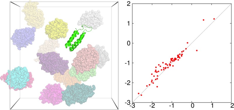
Recently, we (Qin, S.; Zhou, H. X. J. Chem. Theory Comput.2013, 9, 4633–4643) developed the FFT-based method for Modeling Atomistic Proteins–crowder interactions, henceforth FMAP. Given its potential wide use for calculating effects of crowding on protein folding and binding free energies, here we aimed to optimize the accuracy and speed of FMAP. FMAP is based on expressing protein–crowder interactions as correlation functions and evaluating the latter via fast Fourier transform (FFT). The numerical accuracy of FFT improves as the grid spacing for discretizing space is reduced, but at increasing computational cost. We sought to speed up FMAP calculations by using a relatively coarse grid spacing of 0.6 Å and then correcting for discretization errors. This strategy was tested for different types of interactions (hard-core repulsion, nonpolar attraction, and electrostatic interaction) and over a wide range of protein–crowder systems. We were able to correct for the numerical errors on hard-core repulsion and nonpolar attraction by an 8% inflation of atomic hard-core radii and on electrostatic interaction by a 5% inflation of the magnitudes of protein atomic charges. The corrected results have higher accuracy and enjoy a speedup of more than 100-fold over those obtained using a fine grid spacing of 0.15 Å. With this optimization of accuracy and speed, FMAP may become a practical tool for realistic modeling of protein folding and binding in cell-like environments.
1. Introduction
In cellular compartments, the presence of high concentrations of bystander macromolecules (or crowders) may significantly affect protein folding and binding free energies.1−3 Earlier modeling of crowding effects focused on hard-core repulsion between the test protein and the crowders.1,4−13 Recent experimental studies have shown that soft interactions, operating at longer range and having weaker distance dependence, can counterbalance the effect of hard-core repulsion.14−22 The balancing act of hard-core and soft interactions has been reinforced by computational studies and theoretical analyses.23−28
That the net effects of crowding are determined by the balance of hard-core and soft interactions increases the complexity of modeling such effects and raises the level of accuracy necessary when one aims to model protein–crowder systems of experimental studies. In the past, many computational studies have treated the test protein at a coarse-grained level and the crowders as spherical particles.4,5,10−12,26 An approach in which protein conformations from crowder-free simulations are weighted by the excess chemical potential of the protein has opened the door for modeling effects of crowding at the atomic level.6,7,22,25 This “postprocessing” approach7 predicts the change in the folding or binding free energy by crowding, not the latter quantity itself. The excess chemical potential, Δμ(X), arises from interactions with crowders and is given by29,30
| 1 |
where Uint(X, R) is the protein–crowder interaction energy for protein conformation X and position R inside the crowder solution, kB is Boltzmann’s constant, T is the absolute temperature, and ⟨...⟩R;c means averaging over the position of the test protein and the configuration of the crowders. Implementation of this approach by brute-force calculations of Δμ(X) turned out to be extremely expensive.25 Recently we developed a method that allows the full potential of the postprocessing approach to be realized.31 This method is based on expressing the protein–crowder interactions as correlation functions and evaluating the latter via fast Fourier transform (FFT).
In this FMAP (FFT-based Modeling of Atomistic Proteins-crowder interactions) method, both the protein position and the protein–crowder interaction functions are discretized on a grid. Both types of discretization errors can be reduced by decreasing the grid spacing, but at increased computational cost. The aim of the present study was to optimize the accuracy and speed of FMAP. Our tests through exhaustively enumerating all protein–crowder atom pairs, referred to as the atom-based method (similar to the brute-force method of McGuffee and Elcock25), which is free of the errors from mapping the interaction functions to the grid, showed that the errors from discretizing protein positions become negligible at a 0.6 Å grid spacing. On the other hand, errors from discretizing the interaction functions in FMAP calculations persist even to a 0.15 Å grid spacing, although extrapolation to 0 grid spacing reaches agreement with the atom-based method. However, we were able to correct for the latter type of discretization errors. The corrected results have higher accuracy and enjoy a speedup of more than 100-fold over those obtained using a fine grid spacing of 0.15 Å. This optimization of accuracy and speed positions FMAP for wide usage for realistic modeling of protein folding and binding in cell-like environments and may be instructive for improving other methods that employ discretization of space.
2. Computational Details
2.1. The Interaction Energy
The protein–crowder interaction energy is a potential of mean force, with other solvent degrees of freedom averaged out. Our potential function consisted of the Lennard-Jones and Debye–Hückel potentials, which are commonly used to model intermolecular interactions.25,32−35 Specifically, we modeled steric, van der Waals, and hydrophobic interactions together using the Lennard-Jones potential
| 2 |
where rij denotes the distance between crowder atom i and protein atom j. We refer to σii/2 as the hard-core radius of atom i and dij ≡ (σii + σjj)/2 as the distance of closest approach between atoms i and j. Electrostatic interactions were modeled by the Debye–Hückel potential
| 3 |
where qi are atomic charges and λ and κ are the Debye screening length and the dielectric constant, respectively, of the crowder solution.
In calculating Δμ(X), the test protein could be placed anywhere in the crowder solution, including positions where rij approaches zero, and hence ULJ (as well as UDH) has exceedingly large magnitudes. Partly to minimize possible numerical uncertainties associated with such positions, we split ULJ into a steric term Ust and a nonpolar attraction term Una (Figure 1):
| 4 |
and
| 5 |
When dij = σij (true, e.g., for the interaction between two atoms of the same type), the split of ULJ into Ust and Una occurs where ULJ = 0. We also set UDH to 0 if any rij < dij, thus stipulating that the Debye–Hückel potential operated only when the protein was free of steric clash with the crowders. The resulting total interaction energy is
| 6 |
Ust represents the hard-core repulsion, while Una and UDH are soft interactions.
Figure 1.
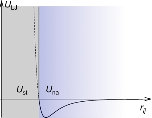
Split of ULJ into Ust and Una at rij = dij, when only a pair of atoms is considered. If the two atoms are of the same type, then dij = σij; the latter is the interatomic distance where ULJ = 0. For two different types of atoms, dij is slightly larger than σij, and hence when the split is triggered, Una would be slightly negative instead of 0.
We emphasize that the steric term is triggered not at the level of each protein–crowder atom pair but globally, i.e., when all the atom pairs are considered. If at least one atom pair has rij < dij, then the protein is labeled as clashing with the crowders, and the steric term is imposed and the soft interactions are turned off. In practice, we first evaluated the soft interactions without considering clash. Based on a separate detection for clash, we then decided on using either the steric term or the soft interactions for the total interaction energy. To avoid floating-point overflow, we set the values of the soft interactions for atom pairs at rij < 1 Å to the values at rij = 1 Å. This treatment did not introduce any errors since the soft interactions at rij < 1 Å would not be used ultimately, as any rij < 1 Å would trigger the clash condition.
We used Autodock parameters34 for the Lennard-Jones potential (εαα and σαα of atom type α) and Amber parameters36 for the atomic charges (qα). For Lennard-Jones interactions between different atom types, we used the combination rule εαβ = (εααεββ)1/2 and σαβ = (σαασββ)1/2. This combination allows the two terms of the Lennard-Jones potential to be written as correlation functions (see below) and hence evaluation via FFT. The resulting σαβ is slightly less than the distance of closet approach dαβ defined above; so for the interaction between two different types of atoms, the split of ULJ into Ust and Una occurs at an interatomic distance where ULJ is slightly negative. We used the dielectric constant of pure water for κ, but to achieve a better balance between Una and UDH, we scaled Una down 5-fold and scaled UDH up 2-fold. Parameter tuning to achieve agreement with experimental measurements is left for future studies.
2.2. Discretizing the Protein Position on a Grid and the Atom-based Method
The averaging in eq 1 over the protein position inside the crowder solution can potentially be a very expensive part of the postprocessing approach. The first approximation of FMAP is to use points on a cubic grid for the averaging over R, assuming that the crowder configuration is generated from a simulation with periodic boundary conditions. We further separated the grid points where the protein would clash with a crowder from clash-free grid points. The averaging over R can be written as
| 7 |
where ⟨...⟩0 and ⟨...⟩1 signify averaging over all the grid points and over only the clash-free grid points, respectively. Note that exp(−Ust/kBT) is either 0 or 1, when the protein is centered at a clashed or clash-free grid point. Therefore, ⟨exp(−Ust/kBT)⟩0 is equal to the fraction of clash-free grid points. We first evaluated the soft interactions for the protein centered at all the grid points without considering clash and then used only those at the clash-free grid points for the averaging of ⟨exp[−(Una + UDH)/kBT]⟩1.
To find the grid spacing necessary for reaching convergence in the Boltzmann average over R and also to provide a benchmark for assessing the accuracy of the FMAP method, we implemented eq 7 using the atom-based method, whereby all the protein–crowder atom pairs are exhaustively enumerated. To cut down the cost of the expensive atom-based calculations, we introduced a 12 Å cutoff (denoted as rcut) for the soft interactions (the same cutoff was also applied in FMAP calculations). In addition, to minimize the enumeration of atom pairs with rij > rcut, crowder atoms were assigned indices according to their partitions in cubic cells with side length of rcut/2.37 For each protein atom, only crowder atoms in the two nearest neighboring cells in each of the six directions were selected for calculations of interatomic distances and intermolecular interactions.
Our application of the atom-based method to model systems containing a small number of crowder molecules showed that the Boltzmann average over R reached convergence when the grid spacing, Δ, was reduced to 0.6 Å. For the full systems presented below, we will further verify that Δ = 0.6 Å is sufficient for the discretization of R.
2.3. Mapping the Interaction Functions to the Grid
The second approximation of FMAP is to express exp(−Ust/kBT), Una, and UDH as discrete correlation functions on the grid. In the previous paper,31 we detailed the treatment of the hard-core repulsion and outlined the treatment of soft interactions. Below we summarize the procedure for the hard-core repulsion and present details and improvements herein for the soft interactions studied here.
For calculating exp(−βUst), we represented the crowder atoms by a function f(n) on the grid, with the grid point n assigned a value of 1 if it fell within the hard core of any crowder atom and a value of 0 otherwise. The test protein, while centered in the middle of the grid (where n = 0), was represented by an analogously valued function g(n). Protein–crowder clash would occur at n if both f(n) and g(n) are 1. When the protein is centered at an arbitrary grid point m, the correlation function
| 8 |
would equal 0 if the protein is free of clash with any crowder and be ≥1 with clash. If H(l) is a function with value 1 when l = 0 and value 0 when l ≥ 1, then exp(−βUst) = H[c(m)].
Both UDH and the two separate terms of Una can be written in the form
| 9 |
with u(rij) = exp(−rij/λ)/κrij, 4/rij12, and −4/rij6, respectively, and γi = qi, εii1/2σii6, and εii1/2σii3, respectively. This U can be interpreted as the energy for the protein’s “charges” γj in an “electric” potential
| 10 |
due to the crowders (Figure 2A). If we distribute γj to neighboring grid points and denote the sum of these distributions (from different atoms) at n by g(n) (Figure 2B), then U can be approximated by the correlation of f(n) and g(n) (Figure 2C).
Figure 2.
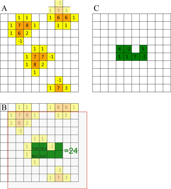
Illustration of FMAP. (A) The crowders generate a potential, consisting of hard-core values (orange grid points) near atomic centers and soft values at nearby (yellow) grid points. (B) The charges of the test protein are distributed to (green) grid points. (C) For a given placement of the protein, the protein–crowder interaction energy is obtained by multiplying the potential with the charge at each grid point and then adding up the products.
Previously, we distributed γj to the eight grid points forming the smallest enclosing cube, according to trilinear interpolation.31 Here, we assessed this protocol against the atom-based method and found it to be satisfactory for the two terms of Una, thanks to their rapid decay with increasing rij. However, due to the relatively slower decay of UDH, we found that trilinear interpolation of qj resulted in significant errors. We also tested a B-spline distribution of the atomic charges, which has been implemented in the smooth particle mesh Ewald method for molecular dynamics simulations38 and in the Adaptive Poisson–Boltzmann Solver,39 but did not find significant improvement in accuracy.
We finally settled on a method that guarantees the accuracy of the energy of an atomic charge up to the second order in a Taylor expansion. The energy of a charge q at position r is qf(r). Suppose that this charge is distributed, with amounts {ρl} at a set of grid points {nl}. The energy of the distributed charges is ∑lρlf(nl). The Taylor expansion of the latter in terms of the displacements δl ≡ nl – r is
| 11 |
For this result to be exact up to the second order in δl, we must have
| 12 |
which constitute 10 independent linear equations for {ρl}. A unique solution for {ρl} can be found if q is distributed to 10 grid points. We chose the 10 grid points in the following way (Figure 3): (i) start with the eight grid points forming the smallest enclosing cube, and remove the one farthest from q; (ii) identify the one closest to q, and then add the three nearest neighbors outside the enclosing cube.
Figure 3.
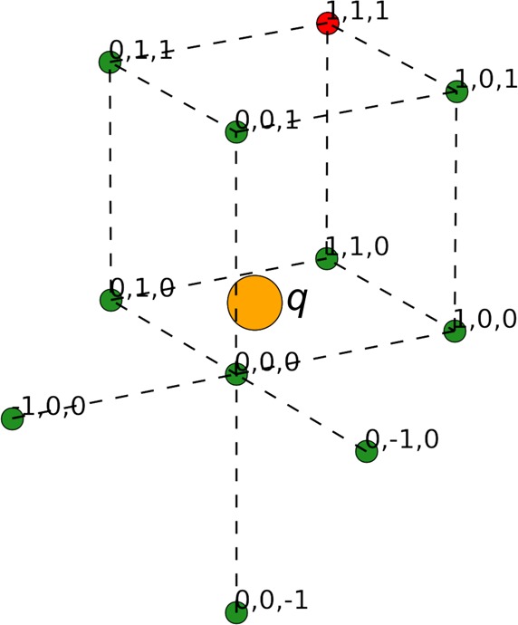
Selection of 10 grid points for distributing an atomic charge q. The eight grid points forming the smallest enclosing cube are labeled with index 0 or 1 in each direction. In the case shown, the grid point at (0, 0, 0) is closest to q, whereas the grid point (shown red) at (1, 1, 1) is farthest from q. All but the last grid point, plus the three external nearest neighbors of (0, 0, 0), at (−1, 0, 0), (0, −1, 0), and (0, 0, −1), are included for charge distribution.
To save time for the charge distribution, we precomputed the distribution for a full charge (i.e., q = 1) located at each position on a subgrid. The subgrid consisted of 1000 positions, generated with 1/10th of the original grid spacing Δ, to sample the enclosing cube. For each atomic charge qj, we located the nearest point on the subgrid and then took its precomputed charge distribution {ρl}. The latter, when multiplied by qj, and the associated grid points {nl} then allowed for the distribution of the atomic charge.
We computed the potential function f(n) by exhaustively enumerating the contributions of each crowder atom to the grid points within the cutoff distance. A main intended use of FMAP is for studying different test proteins in selected crowder solutions.31 For this purpose we can compute f(n) and its Fourier transform F(k) once and save for later use on different test proteins. This computation is affordable at Δ = 0.6 Å. Here for the optimization of FMAP, we needed results at smaller Δ. Instead of trying to speed up the computation of f(n), we found an alternative solution, based on the fact that the energy can be calculated by either multiplying the crowders’ potential with the protein’s charges, as presented above, or vice versa. We confirmed that the two ways of calculating the energy gave essentially identical results, at least at Δ ≤ 0.6 Å. While there are multiple crowder molecules within the grid, there is only a single protein molecule. Therefore, computing the potential of the protein is much faster than that of the crowders. The results presented below for Δ < 0.6 Å (other than those on timing) were all obtained by treating the test protein as the source of potential.
2.4. Implementation of FMAP
In FMAP, we evaluate the correlation function of eq 8 via FFT, taking advantage of the fact that, in Fourier space, the correlation function is a direct product:
| 13 |
After the forward Fourier transforms of f(n) and g(n) and then the inverse Fourier transform of C(k), we obtain the values of c(m) at all the grid points, allowing the Boltzmann average over R to be calculated at once. We used the free library FFTW (version 3.3; double precision)40 for computing the discrete Fourier transforms.
As explained already, the protein–crowder interaction energy used here involves four correlation functions: one for the hard-core repulsion, two for the soft attraction, and one for the electrostatic interaction. The values of these terms at the grid points were all saved on disk for repeated later use, such as different combinations of terms or scaling of individual terms.
2.5. Test Proteins and Their Conformations
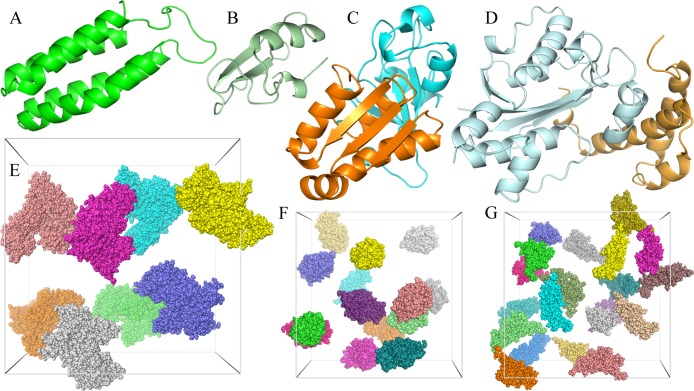
We studied two proteins, cytochrome b562 and chymotrypsin inhibitor 2 (CI2), in the native and unfolded states, and two pairs of proteins, barnase:barstar and the ε and θ subunits of the Escherichia coli DNA polymerase III holoenzyme (Figure 4A–D), in the unbound and bound states. In all there were 10 distinct test protein systems. Eight of these were studied previously under crowding by spherical or ellipsoidal particles.6,31,41 For each system, we took one conformation (i.e., the first of an ensemble collected from molecular dynamics simulations) for the study here. In future applications of FMAP, averaging over orientation and conformation of the test protein as well as over the crowder configuration will need to be carried out in order to obtain convergent results.
Figure 4.
Test proteins and crowders studied here. (A) Cytochrome b562. (B) CI2. (C) The barnase:barstar complex. (D) The ε:θ complex. (E) Eight copies of BSA in a (200 Å)3 box. (F) Fourteen copies of lysozyme in a (150 Å)3 box. (G) Twenty copies of dextran 10K in a (150 Å)3 box.
The two new systems added here are native and unfolded CI2. Their conformations were generated from room-temperature and high-temperature simulations (293 and 550 K), respectively, following the protocol of a previous study.42 Briefly, the initial structure was from Protein Data Bank (PDB) entry 2CI2 (residues 20–83),43 with mutations L20M, I49A, and I56A introduced to match the sequence in an experimental study of crowding effects on folding stability.14 The protein was solvated by TIP3P water molecules and Na+ and Cl– ions at 0.05 M (plus counterions that neutralized the charge of CI2) in a box with a side length of 66 (or 110) Å for the 293 (or 550) K simulation. The simulation at either 293 or 550 K was run using the GROMACS (version 4.5.4) program,44 with the Amber99SB force field45 and a time step of 2 or 1 fs, and at constant pressure or volume. All bond lengths involving hydrogen atoms were constrained. Long-range electrostatic interactions were treated by the particle mesh Ewald method38 with a grid spacing of 1.6 Å and a direct-space cutoff of 10 Å. A cutoff of 10 Å was used for evaluation of Lennard-Jones interactions. The snapshot at 100 (or 10) ns in the 293 (or 550) K simulation was used for the conformation of native (unfolded) CI2.
2.6. Generation of Crowder Configurations
We studied three kinds of crowders: bovine serum albumin (BSA), lysozyme, and dextran 10K (Figure 4E-G). The structure of BSA was modeled by homology using MODELER,46 with residues 25–607 of the sequence (UniProtKB P02769) aligned to the structure of the human protein in PDB entry 1AO6.47 The structure of lysozyme was taken from PDB entry 1AKI.48 Dextran (molecular weight 9923.8) was built with 61 monosaccharide units49 using Amber parameters (http://www.pharmacy.manchester.ac.uk/bryce/amber). BSA at 110 g/L, lysozyme at 100 g/L, and dextran at 100 g/L were created by placing eight copies in a box with a side length of 200 Å, 14 copies in a box with a side length of 150 Å, and 20 copies in a box with a side length of 150 Å. In each case, two crowder configurations were studied. One was obtained by randomly placing the crowder molecules into the box while ensuring no clash between the molecules.31 The other was taken from a subsequent molecular dynamics simulation similar to that described above for CI2 at 293 K. The snapshots used for BSA, lysozyme, and dextran were at 70, 95, and 10 ns, respectively, of the simulations. In addition, we generated a crowder configuration for dextran at 200 g/L by randomly placing 40 copies in the (150 Å)3 box.
3. Results
We carried out FMAP calculations for the combinations of the 10 test protein systems and seven distinct crowder configurations at grid spacings ranging from 1.0 to 0.12 Å. For the ε:θ complex interacting with dextran at 200 g/L, a very low fraction of clash-free placements rendered the results spurious. The FMAP results for the remaining 69 protein–crowder combinations are all reliable. For a subset of these combinations, we also applied the atom-based method to verify that the 0.6 Å grid spacing is adequate for the Boltzmann average over R and also to provide a benchmark for assessing the accuracy of FMAP.
Accuracy was assessed on the Boltzmann average of the total interaction energy, which yields the excess chemical potential Δμ, as well as on the Boltzmann averages calculated with individual terms of the interaction energy selectively included, all at T = 298 K. We loosely refer to the quantities yielded by the latter Boltzmann averages as components of Δμ. Specifically, the steric component, Δμst, is defined through
| 14 |
whereas the nonpolar-attraction and electrostatic components are defined through
| 15 |
| 16 |
Note that the sum of these three components does not equal Δμ, because Una and UDH are not uncorrelated. Indeed, grid points where UDH is most negative (and thus make the most electrostatic contribution to Δμ) are often also where Una has large negative values. As a result, Δμ tends to be more negative than expected from additivity.
3.1. Benchmark Results Obtained from Extrapolation to 0 Grid Spacing
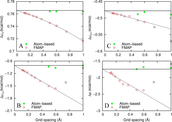
Figure 5 displays the dependences of Δμ and its components on the grid spacing Δ for native cytochrome b562 in 100 g/L of lysozyme. The Δ dependences for this and other protein–crowder systems are all apparently linear when Δ ≤ 0.6 Å. For Δμst in particular, the calculated values were so precise that a curvature was discernible in the dependence on Δ. We thus fitted Δμna, ΔμDH, and Δμ to a linear function of Δ (including only data at Δ ≤ 0.6 Å) and Δμst to a quadratic function of Δ (including all data).
Figure 5.
Grid-spacing dependences of FMAP and atom-based results for native cytochrome b562 in 100 g/L of lysozyme (with a configuration generated by random placement). (A) Δμst. (B) Δμna. (C) ΔμDH. (D) Δμ. Open and closed circles display FMAP and atom-based results, respectively. Dashed lines (curve) are linear (quadratic) fits using data displayed as red circles. Note that the extrapolated FMAP results at 0 grid spacing, represented by solid horizontal lines, agree closely with those from the atom-based method. All the FMAP results here and in Figure 6 were obtained by treating the test protein as the source of potential when evaluating the soft interactions.
Given the good quality of these fits, we expect that the extrapolated values at Δ = 0 should be free of discretization errors. Indeed, the extrapolated values agree closely with those calculated by the atom-based method (with Δ = 0.5 or 0.6 Å). The agreement of the atom-based results themselves at these two grid spacings verifies that Δ = 0.6 Å is sufficient for the discretization of R (this method became prohibitively expensive at lower grid spacings). Hereafter, we will use the extrapolated FMAP results as benchmarks for assessing the accuracy of FMAP at finite grid spacing.
3.2. Corrections of FMAP Results at 0.6 Å Grid Spacing
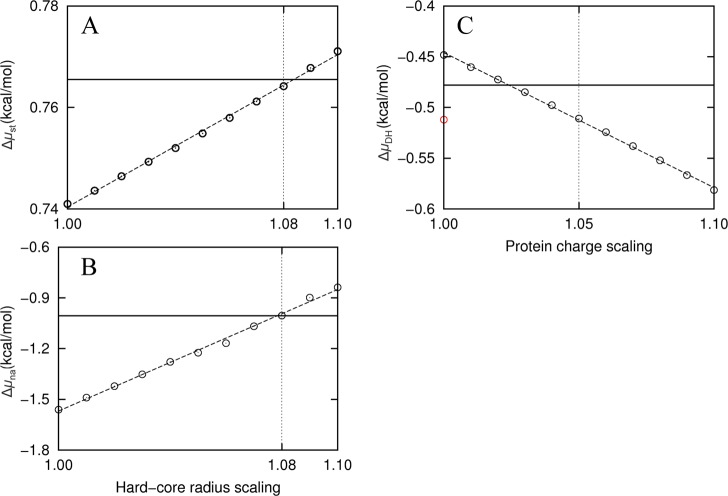
For all 69 protein–crowder combinations studied, we found a negative slope in the dependence of Δμst on Δ. This observation suggests that FMAP systematically underestimated the fraction of clashed grid points, perhaps due to rounding off of hard-core regions when the protein and crowders were mapped to the grid. A way to compensate such round off is to inflate the hard-core radii. Figure 6A shows that radius inflation does have the desired effect for native cytochrome b562 in 100 g/L of lysozyme. An 8% inflation brings the FMAP result for Δμst at Δ = 0.6 Å into agreement with the extrapolated benchmark. The amount of radius inflation needed showed very little variation among the different protein–crowder combinations.
Figure 6.
Corrections of FMAP at 0.6 Å grid spacing, illustrated using the results for native cytochrome b562 in 100 g/L of lysozyme. (A) Correcting for Δμst by inflating the hard-core radii when detecting for protein–crowder clash. The extrapolated benchmark is shown as a solid horizontal line; the FMAP results calculated at 0.6 Å grid spacing but with hard-core radii inflated by 1% to 10% are shown as circles. (B) Δμna calculated after filtering of grid points using inflated radii. (C) ΔμDH at I = 0.15 M. The value before filtering of grid points is shown as a red circle. After filtering with 8% radius inflation, ΔμDH had a smaller magnitude than the extrapolated benchmark. Scaling up by ∼3% would correct the underestimate in this case, but on average 5% correction is needed at I = 0.15 M for all the protein–crowder combinations studied.
With Δ = 0.6 Å, FMAP systematically overestimated the magnitude of Δμna (Figure 5B). The grid points that are filtered by the radius inflation are positions where the protein would have close contact with one or more crowder molecules. It is likely that, at a subset of these grid points, Una has large negative values (see below). Filtering these grid points would thus be expected to reduce the magnitude of Δμna. Figure 6B shows that, indeed, the magnitude of Δμna decreases as the radius scaling factor is increased. Note that Una at all the grid points was calculated once and then used for obtaining all the Δμna results when the amount of radius inflation was varied. To our pleasant surprise, agreement with the extrapolated benchmark for Δμna is reached also at 8% radius inflation. Again, the radius scaling factor is stable among the different protein–crowder combinations. We thus settled on an 8% radius inflation for the corrections of both the hard-core and soft interactions.
After the filtering with the 8% radius inflation, ΔμDH calculated over the remaining clash-free grid points at Δ = 0.6 Å had an underestimated magnitude (Figure 6C). As a correction, we scaled up the magnitude of ΔμDH (Figure 6C), which is equivalent to a scaling of the protein atomic charges. The charge scaling factor (denoted ξ) is also pretty constant among the different protein–crowder combinations, averaging at 1.05 for 0.15 M ionic strength (denoted I). The charge scaling factor has a distinct dependence on ionic strength, approaching 1 as I increases. This trend is to be expected, since UDH decays faster at higher I so the correction needed should reduce accordingly. The average charge scaling factor over the ionic strength range of 0.05 to 0.25 M can be represented by the relation ξ = 1 + 0.025I–0.4.
To verify that the corrections for the components of the excess chemical potential went to the root of the discretization errors, we investigated how the corrections impacted the values of the corresponding interactions at the individual grid points. Again we use native cytochrome b562 in 100 g/L of lysozyme for illustration. According to the atom-based method, of the 15.63 × 10⁶ grid points generated with Δ = 0.6 Å, 4.29 × 10⁶ grid points, or 27.5%, are clash-free. Without radius inflation, FMAP yielded a 28.5% clash-free fraction, which covered all the true clash-free grid points, but also included 0.17 × 10⁶ false-positive grid points. With the 8% radius inflation, FMAP filtered 81% of the false positives along with just 0.8% of the true clash-free grid points.
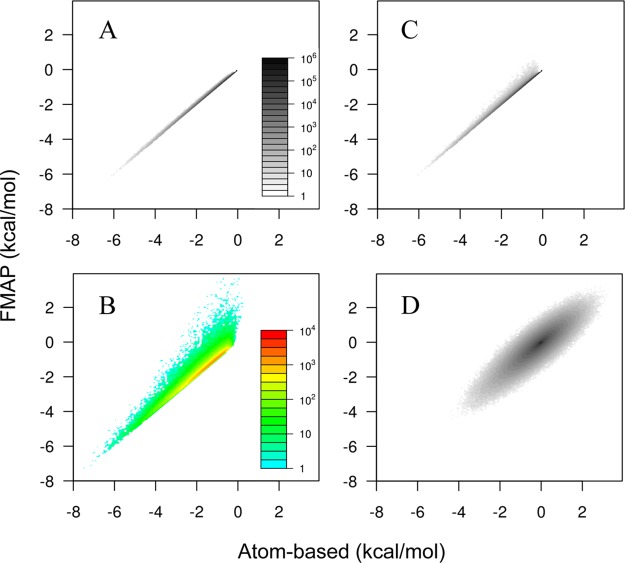
As shown in Figure 7A, at the true clash-free grid points, the FMAP values for Una were highly accurate when benchmarked against the atom-based method. At the grid points that were filtered by the 8% radius inflation, the would-be FMAP values for Una overall tended to be not as negative as would be determined by the atom-based method if clash were disregarded (Figure 7B). However, as we suspected, among these to-be filtered grid points, there was a small subset with strongly negative Una values. It is indeed this subset of grid points that was responsible for the overestimation in the magnitude of Δμna when FMAP was uncorrected. After filtering with the 8% radius inflation, the range and distribution of the FMAP values for Una (Figure 7C) are very similar to those determined by the atom-based method. On the other hand, after the filtering of grid points and the scaling of magnitudes (5% at I = 0.15 M), the FMAP values for UDH still have a 0.29 kcal/mol root-mean-square-deviation (RMSD) from the atom-based counterparts. Importantly, the deviations are roughly even in the opposite directions (Figure 7D), so that ΔμDH resulting from their Boltzmann average has a much small error (0.03 kcal/mol).
Figure 7.
Accuracy assessment of FMAP values for Una and UDH at the individual grid points against the atom-based method, illustrated on native cytochrome b562 in 100 g/L of lysozyme (with the latter treated as the source of potential when evaluating the soft interactions; Δ = 0.6 Å and I = 0.15 M). The results are shown as two-dimensional histograms, where the abscissa represents bins of atom-based interaction energies at 0.06 kcal/mol intervals, and the ordinate represents the FMAP counterparts, and the gray or color scale represents the number of (true or nominal) clash-free grid points in a two-dimensional cell. True clash-free grid points are those identified as such by the atom-based method. Nominal clash-free grid points are those identified by FMAP, without or with the 8% radius inflation. This inflation serves to filter a subset of the former nominal clash-free grid points. (A) At the true clash-free grid points, the FMAP values for Una were highly accurate, as shown by significant densities only in the diagonal cells. (B) Among the grid points filtered through the radius inflation, FMAP values for Una were skewed toward the less negative direction; there was also a subset with strongly negative Una values, which led to an overestimated magnitude for Δμna. (C) After filtering, the histogram for the remaining nominal clash-free grid points looks very similar to that calculated at the true clash-free grid points. (D) Densities in off-diagonal cells indicate inaccuracy in the corrected FMAP results for UDH, but the nearly symmetric distribution of the densities with respect to the diagonal would lead to significant error cancelation in calculating ΔμDH.
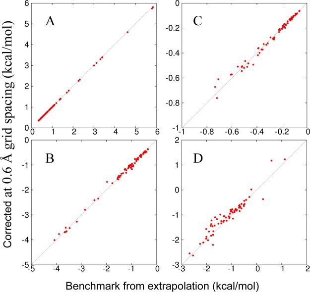
After the corrections with the 8% radius inflation and the 5% magnitude inflation for UDH, the FMAP results at Δ = 0.6 Å for the components of Δμ and for Δμ itself become highly accurate for all the 69 protein–crowder combinations studied when compared to the extrapolated benchmarks (Figure 8 and Table 1). Specifically, with the test protein treated as the source of potential when evaluating the soft interactions, the RMSDs for Δμst, Δμna, ΔμDH, and Δμ are 0.009, 0.07, 0.02, and 0.23 kcal/mol, respectively. The last value is even somewhat lower than the RMSD, 0.30 kcal/mol, of the uncorrected FMAP results at Δ = 0.15 Å and would require Δ = 0.12 Å without corrections. With the corrections listed above, essentially identical results were obtained when the crowders were treated as the source of potential.
Figure 8.
Comparison of corrected FMAP results at Δ = 0.6 Å for the 69 protein–crowder combinations against the extrapolated benchmarks. (A) Δμst. (B) Δμna. (C) ΔμDH at I = 0.15 M. (D) Δμ. Results were obtained by treating the test protein as the source of potential when evaluating the soft interactions. The numerical values and identities of the protein–crowder systems are listed in Table 1.
Table 1. Extrapolated Benchmarks and Corrected FMAP Results at Δ = 0.6 Å (in kcal/mol) for the 69 Protein–Crowder Combinations.
| Δμst |
Δμna |
ΔμDH |
Δμ |
||||||
|---|---|---|---|---|---|---|---|---|---|
| protein | crowder | extrap. | Δ at 0.6 | extrap. | Δ at 0.6 | extrap. | Δ at 0.6 | extrap. | Δ at 0.6 |
| b562n | BSA | 0.596 | 0.595 | –0.615 | –0.583 | –0.179 | –0.191 | –0.831 | –0.764 |
| BSAsim | 0.471 | 0.470 | –0.447 | –0.500 | –0.122 | –0.130 | –1.806 | –1.220 | |
| Dex100 | 1.198 | 1.193 | –1.334 | –1.331 | –0.226 | –0.214 | –1.002 | –0.853 | |
| Dex100sim | 0.737 | 0.734 | –0.998 | –1.071 | –0.136 | –0.128 | –0.957 | –0.903 | |
| Dex200 | 3.410 | 3.395 | –3.664 | –3.691 | –0.602 | –0.571 | –1.452 | –0.986 | |
| Lys | 0.765 | 0.764 | –1.006 | –1.006 | –0.478 | –0.511 | –1.744 | –2.201 | |
| Lyssim | 0.542 | 0.541 | –0.620 | –0.665 | –0.430 | –0.493 | –1.945 | –2.016 | |
| b562u | BSA | 0.723 | 0.722 | –0.608 | –0.682 | –0.090 | –0.090 | –0.288 | –0.282 |
| BSAsim | 0.562 | 0.562 | –0.480 | –0.486 | –0.060 | –0.061 | –0.421 | –0.398 | |
| Dex100 | 1.361 | 1.356 | –1.432 | –1.429 | –0.188 | –0.178 | –0.682 | –0.604 | |
| Dex100sim | 0.900 | 0.898 | –1.267 | –1.187 | –0.132 | –0.123 | –0.971 | –0.776 | |
| Dex200 | 5.793 | 5.739 | –3.893 | –3.767 | –0.709 | –0.610 | 1.128 | 1.226 | |
| Lys | 0.976 | 0.975 | –1.101 | –1.028 | –0.363 | –0.372 | –1.528 | –1.350 | |
| Lyssim | 0.675 | 0.675 | –0.978 | –1.166 | –0.202 | –0.205 | –1.818 | –1.832 | |
| CI2n | BSA | 0.414 | 0.413 | –0.399 | –0.467 | –0.097 | –0.101 | –0.606 | –0.741 |
| BSAsim | 0.350 | 0.350 | –0.337 | –0.375 | –0.079 | –0.083 | –0.511 | –0.648 | |
| Dex100 | 0.767 | 0.764 | –1.086 | –1.047 | –0.139 | –0.131 | –0.850 | –0.773 | |
| Dex100sim | 0.521 | 0.520 | –0.744 | –0.754 | –0.091 | –0.085 | –0.672 | –0.703 | |
| Dex200 | 2.329 | 2.321 | –2.854 | –2.793 | –0.390 | –0.363 | –1.816 | –1.369 | |
| Lys | 0.522 | 0.522 | –0.863 | –0.757 | –0.191 | –0.193 | –1.286 | –1.055 | |
| Lyssim | 0.383 | 0.382 | –0.500 | –0.495 | –0.125 | –0.128 | –1.119 | –1.058 | |
| CI2u | BSA | 0.540 | 0.540 | –0.408 | –0.479 | –0.119 | –0.122 | 0.255 | –0.371 |
| BSAsim | 0.438 | 0.438 | –0.342 | –0.363 | –0.085 | –0.088 | –0.510 | –0.596 | |
| Dex100 | 0.980 | 0.978 | –1.027 | –1.111 | –0.140 | –0.132 | –0.604 | –0.558 | |
| Dex100sim | 0.661 | 0.659 | –0.726 | –0.709 | –0.092 | –0.086 | –0.496 | –0.435 | |
| Dex200 | 3.129 | 3.121 | –3.179 | –3.272 | –0.494 | –0.464 | –1.335 | –1.274 | |
| Lys | 0.695 | 0.694 | –0.806 | –0.783 | –0.172 | –0.174 | –1.045 | –0.797 | |
| Lyssim | 0.503 | 0.502 | –0.513 | –0.502 | –0.112 | –0.113 | –0.700 | –0.713 | |
| bn | BSA | 0.568 | 0.567 | –0.633 | –0.668 | –0.197 | –0.207 | –1.765 | –1.464 |
| BSAsim | 0.455 | 0.454 | –0.493 | –0.512 | –0.132 | –0.139 | –1.308 | –1.233 | |
| Dex100 | 1.115 | 1.111 | –1.554 | –1.558 | –0.195 | –0.183 | –1.083 | –1.096 | |
| Dex100sim | 0.722 | 0.719 | –1.399 | –1.350 | –0.131 | –0.123 | –1.093 | –1.130 | |
| Dex200 | 3.400 | 3.385 | –3.625 | –3.512 | –0.518 | –0.506 | –1.662 | –1.095 | |
| Lys | 0.722 | 0.721 | –1.101 | –1.068 | –0.216 | –0.218 | –1.741 | –1.800 | |
| Lyssim | 0.504 | 0.503 | –0.663 | –0.634 | –0.131 | –0.132 | –1.010 | –0.786 | |
| bn:bs | BSA | 0.859 | 0.857 | –1.245 | –1.159 | –0.271 | –0.286 | –1.835 | –1.436 |
| BSAsim | 0.607 | 0.607 | –0.805 | –0.769 | –0.168 | –0.176 | –1.198 | –1.232 | |
| Dex100 | 1.797 | 1.790 | –2.477 | –2.407 | –0.346 | –0.328 | –1.757 | –1.454 | |
| Dex100sim | 1.060 | 1.059 | –1.971 | –1.676 | –0.182 | –0.169 | –1.904 | –1.666 | |
| Dex200 | 5.836 | 5.801 | –4.074 | –4.009 | –0.734 | –0.672 | 0.595 | 1.175 | |
| Lys | 1.086 | 1.085 | –1.536 | –1.491 | –0.503 | –0.519 | –2.681 | –2.543 | |
| Lyssim | 0.747 | 0.746 | –0.857 | –0.925 | –0.313 | –0.322 | –1.412 | –1.337 | |
| bs | BSA | 0.486 | 0.485 | –0.523 | –0.550 | –0.086 | –0.091 | –0.681 | –0.662 |
| BSAsim | 0.397 | 0.397 | –0.443 | –0.443 | –0.061 | –0.065 | –0.651 | –0.683 | |
| Dex100 | 0.914 | 0.911 | –1.208 | –1.312 | –0.178 | –0.168 | –1.066 | –0.955 | |
| Dex100sim | 0.612 | 0.611 | –0.974 | –0.949 | –0.121 | –0.112 | –1.029 | –0.810 | |
| Dex200 | 3.008 | 2.998 | –3.465 | –3.529 | –0.553 | –0.510 | –1.414 | –1.246 | |
| Lys | 0.638 | 0.637 | –1.043 | –1.000 | –0.521 | –0.544 | –2.262 | –2.161 | |
| Lyssim | 0.451 | 0.451 | –0.626 | –0.615 | –0.393 | –0.418 | –2.021 | –1.952 | |
| ε | BSA | 0.800 | 0.799 | –0.798 | –0.841 | –0.264 | –0.281 | –0.946 | –1.148 |
| BSAsim | 0.582 | 0.581 | –0.525 | –0.560 | –0.155 | –0.162 | –2.013 | –1.567 | |
| Dex100 | 1.704 | 1.696 | –1.761 | –1.730 | –0.291 | –0.275 | –0.890 | –0.838 | |
| Dex100sim | 1.029 | 1.026 | –1.500 | –1.436 | –0.180 | –0.169 | –1.224 | –1.109 | |
| Dex200 | 4.617 | 4.601 | –3.590 | –3.655 | –0.522 | –0.511 | –0.213 | 0.019 | |
| Lys | 1.047 | 1.045 | –1.198 | –1.208 | –0.469 | –0.483 | –1.730 | –1.655 | |
| Lyssim | 0.704 | 0.703 | –0.925 | –1.058 | –0.325 | –0.334 | –2.007 | –1.876 | |
| ε:θ | BSA | 1.091 | 1.089 | –0.929 | –1.008 | –0.379 | –0.399 | –1.320 | –1.054 |
| BSAsim | 0.727 | 0.727 | –0.598 | –0.616 | –0.223 | –0.232 | –2.543 | –2.627 | |
| Dex100 | 2.268 | 2.261 | –2.321 | –2.346 | –0.387 | –0.360 | –0.681 | –0.845 | |
| Dex100sim | 1.364 | 1.360 | –1.515 | –1.575 | –0.218 | –0.207 | –0.835 | –0.788 | |
| Lys | 1.404 | 1.403 | –1.470 | –1.491 | –0.720 | –0.761 | –2.134 | –2.105 | |
| Lyssim | 0.945 | 0.943 | –1.126 | –1.128 | –0.354 | –0.373 | –1.678 | –1.427 | |
| θ | BSA | 0.538 | 0.536 | –0.451 | –0.468 | –0.263 | –0.291 | –0.884 | –0.887 |
| BSAsim | 0.445 | 0.445 | –0.337 | –0.364 | –0.175 | –0.198 | –0.788 | –0.802 | |
| Dex100 | 0.987 | 0.984 | –1.091 | –1.075 | –0.155 | –0.146 | –0.705 | –0.629 | |
| Dex100sim | 0.679 | 0.677 | –0.733 | –0.785 | –0.108 | –0.102 | –0.482 | –0.565 | |
| Dex200 | 3.318 | 3.299 | –3.629 | –3.686 | –0.608 | –0.574 | –1.032 | –0.866 | |
| Lys | 0.684 | 0.683 | –0.752 | –0.737 | –0.262 | –0.275 | –1.584 | –1.168 | |
| Lyssim | 0.480 | 0.480 | –0.488 | –0.506 | –0.154 | –0.161 | –0.815 | –0.830 | |
3.3. Gain in Speed at 0.6 Å Grid Spacing
In Figure 9, we display the computational times when FMAP was run on an AMD Opteron 6174 processor with either the crowders or the test protein treated as the source of potential (labeled as Crowders:Protein and Protein:Crowders, respectively), as well as the times for the FFT portion alone, at grid spacings from 1.0 to 0.15 Å, for native cytochrome b562 in 100 g/L of lysozyme. At Δ = 0.6 Å, the FFT portion took 7.5 s, but the “overhead,” mostly the calculation of f(n) and (to a lesser extent) g(n), took even longer for the Protein:Crowders implementation (total time at 18.6 s) but especially for the Crowders:Protein implementation (total time at 121 s). As a comparison, using the atom-based method, the calculation of UDH alone took 417 000 s. As noted above, in future applications we will calculate f(n) and save its Fourier transform for selected crowder systems so that this overhead would not constitute a new cost.
Figure 9.
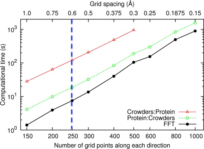
Computational times of FMAP on native cytochrome b562 in 100 g/L of lysozyme at Δ from 1.0 to 0.15 Å. Traces labeled “Crowders:Protein” and “Protein:Crowders” represent total times with the crowders and the test protein, respectively, treated as the source of potential; the trace labeled “FFT” represents the times for the FFT portion of the FMAP calculations.
Focusing on the FFT portion, the computational time at Δ = 0.15 Å was 893.1 s, a 120-fold increase over that at Δ = 0.6 Å. Therefore, with the corrections presented above for Δ = 0.6 Å, we not only achieve higher accuracy but also gain more than 100-fold in speed when compared to the use of a 0.15 Å fine grid spacing. Attaining the same accuracy through using an even finer grid spacing of 0.12 Å would increase the computational time 220-fold.
4. Discussion
We have presented an accurate and efficient implementation of the FMAP (FFT-based Modeling of Atomistic Proteins-crowder interactions) method, based on corrections of results at a relatively coarse grid spacing. Because we represent the crowder molecules on a grid, the core of FMAP (involving FFT operations) would not suffer any loss of computational speed when crowded conditions of cellular compartments are more and more realistically modeled, e.g., through increasing the number of crowder species and other types of complexity. We are thus hopeful that FMAP will become a practical tool for realistic modeling of protein folding and binding in cell-like environments.
A number of important applications of FMAP can be anticipated. The first is the parametrization of the protein–crowder interaction energy.25 With the speed of FMAP, we can afford to do extensive parametrization, e.g., against experimental results for protein folding stability.14−19 Similarly, we will be able to include much more extensive conformational sampling of the test protein in the absence of crowders for predicting the effects of crowding on folding and binding. As noted previously,30,50 the postprocessing approach underlying FMAP is premised on thorough crowder-free sampling for ensuring sufficient overlap with the conformational space of the protein under crowding.
FMAP is in essence a particle-insertion method51 and as such is effective only if there is a statistically significant clash-free fraction. This condition can be broken when inserting a large protein (or complex) into a very concentrated crowder solution, as was found here for the ε:θ complex interacting with dextran at 200 g/L. One way out, as demonstrated in our previously study,31 is to carry out FMAP calculations at lower crowder concentrations and then extrapolate the results to the desired high crowder concentration.
Discretization in general and FFT in particular are widely used in treating intramolecular and intermolecular interactions, such as charge–charge interaction. The optimization of accuracy and speed by correcting for results at a relatively coarse grid spacing perhaps can be instructive for improving other methods that employ discretization of space. In this regard we note an improvement orthogonal to ours, for the smooth particle mesh Ewald method, that involved doing calculations over two coarse grids that were staggered at half grid spacing and then averaging the results.52
Acknowledgments
This work was supported by National Institutes of Health Grant GM88187. We thank Dr. Bernard Brooks for calling our attention to ref (52).
The authors declare no competing financial interest.
Funding Statement
National Institutes of Health, United States
References
- Zhou H. X.; Rivas G.; Minton A. P. Macromolecular crowding and confinement: biochemical, biophysical, and potential physiological consequences. Annu. Rev. Biophys. 2008, 37, 375–397. [DOI] [PMC free article] [PubMed] [Google Scholar]
- Feig M.; Sugita Y. Reaching new levels of realism in modeling biological macromolecules in cellular environments. J. Mol. Graphics Modell. 2013, 45, 144–156. [DOI] [PMC free article] [PubMed] [Google Scholar]
- Zhou H. X. Influence of crowded cellular environments on protein folding, binding, and oligomerization: biological consequences and potentials of atomistic modeling. FEBS Lett. 2013, 587, 1053–1061. [DOI] [PMC free article] [PubMed] [Google Scholar]
- Cheung M. S.; Klimov D.; Thirumalai D. Molecular crowding enhances native state stability and refolding rates of globular proteins. Proc. Natl. Acad. Sci. U.S.A. 2005, 102, 4753–4758. [DOI] [PMC free article] [PubMed] [Google Scholar]
- Minh D. D.; Chang C. E.; Trylska J.; Tozzini V.; McCammon J. A. The influence of macromolecular crowding on HIV-1 protease internal dynamics. J. Am. Chem. Soc. 2006, 128, 6006–6007. [DOI] [PMC free article] [PubMed] [Google Scholar]
- Qin S.; Zhou H. X. Atomistic modeling of macromolecular crowding predicts modest increases in protein folding and binding stability. Biophys. J. 2009, 97, 12–19. [DOI] [PMC free article] [PubMed] [Google Scholar]
- Qin S.; Minh D. D. L.; McCammon J. A.; Zhou H.-X. Method to predict crowding effects by postprocessing molecular dynamics trajectories: application to the flap dynamics of HIV-1 protease. J. Phys. Chem. Lett. 2010, 1, 107–110. [DOI] [PMC free article] [PubMed] [Google Scholar]
- Qin S.; Zhou H.-X. Generalized fundamental measure theory for atomistic modeling of macromolecular crowding. Phys. Rev. E 2010, 81, 031919. [DOI] [PMC free article] [PubMed] [Google Scholar]
- Dong H.; Qin S.; Zhou H. X. Effects of macromolecular crowding on protein conformational changes. PLoS Comput. Biol. 2010, 6, e1000833. [DOI] [PMC free article] [PubMed] [Google Scholar]
- Mittal J.; Best R. B. Dependence of protein folding stability and dynamics on the density and composition of macromolecular crowders. Biophys. J. 2010, 98, 315–320. [DOI] [PMC free article] [PubMed] [Google Scholar]
- Dhar A.; Samiotakis A.; Ebbinghaus S.; Nienhaus L.; Homouz D.; Gruebele M.; Cheung M. S. Structure, function, and folding of phosphoglycerate kinase are strongly perturbed by macromolecular crowding. Proc. Natl. Acad. Sci. U.S.A. 2010, 107, 17586–17591. [DOI] [PMC free article] [PubMed] [Google Scholar]
- Kang M.; Roberts C.; Cheng Y. H.; Chang C. E. A. Gating and intermolecular interactions in ligand-protein association: coarse-grained modeling of HIV-1 protease. J. Chem. Theory Comput. 2011, 7, 3438–3446. [DOI] [PubMed] [Google Scholar]
- Nagarajan S.; Amir D.; Grupi A.; Goldenberg D.; Minton A.; Haas E. Modulation of functionally significant conformational equilibria in adenylate kinase by high concentrations of trimethylamine oxide attributed to volume exclusion. Biophys. J. 2011, 100, 2991–2999. [DOI] [PMC free article] [PubMed] [Google Scholar]
- Miklos A. C.; Sarkar M.; Wang Y.; Pielak G. J. Protein crowding tunes protein stability. J. Am. Chem. Soc. 2011, 133, 7116–7120. [DOI] [PubMed] [Google Scholar]
- Benton L. A.; Smith A. E.; Young G. B.; Pielak G. J. Unexpected effects of macromolecular crowding on protein stability. Biochemistry 2012, 51, 9773–9775. [DOI] [PubMed] [Google Scholar]
- Wang Y.; Sarkar M.; Smith A. E.; Krois A. S.; Pielak G. J. Macromolecular crowding and protein stability. J. Am. Chem. Soc. 2012, 134, 16614–16618. [DOI] [PubMed] [Google Scholar]
- Miklos A. C.; Sumpter M.; Zhou H. X. Competitive interactions of ligands and macromolecular crowders with maltose binding protein. PLoS One 2013, 8, e74969. [DOI] [PMC free article] [PubMed] [Google Scholar]
- Sarkar M.; Smith A. E.; Pielak G. J. Impact of reconstituted cytosol on protein stability. Proc. Natl. Acad. Sci. U.S.A. 2013, 110, 19342–19347. [DOI] [PMC free article] [PubMed] [Google Scholar]
- Guzman I.; Gelman H.; Tai J.; Gruebele M. The extracellular protein VlsE is destabilized inside cells. J. Mol. Biol. 2014, 426, 11–20. [DOI] [PMC free article] [PubMed] [Google Scholar]
- Zhou H. X. SAXS/SANS probe of intermolecular interactions in concentrated protein solutions. Biophys. J. 2014, 106, 771–773. [DOI] [PMC free article] [PubMed] [Google Scholar]
- Goldenberg D. P.; Argyle B. Self crowding of globular proteins studied by small-angle x-ray scattering. Biophys. J. 2014, 106, 895–904. [DOI] [PMC free article] [PubMed] [Google Scholar]
- Goldenberg D. P.; Argyle B. Minimal effects of macromolecular crowding on an intrinsically disordered protein: a small-angle neutron scattering study. Biophys. J. 2014, 106, 905–914. [DOI] [PMC free article] [PubMed] [Google Scholar]
- Douglas J. F.; Dudowicz J.; Freed K. F. Crowding induced self-assembly and enthalpy-entropy compensation. Phys. Rev. Lett. 2009, 103, 135701. [DOI] [PubMed] [Google Scholar]
- Jiao M.; Li H. T.; Chen J.; Minton A. P.; Liang Y. Attractive protein-polymer interactions markedly alter the effect of macromolecular crowding on protein association equilibria. Biophys. J. 2010, 99, 914–923. [DOI] [PMC free article] [PubMed] [Google Scholar]
- McGuffee S. R.; Elcock A. H. Diffusion, crowding & protein stability in a dynamic molecular model of the bacterial cytoplasm. PLoS Comput. Biol. 2010, 6, e1000694. [DOI] [PMC free article] [PubMed] [Google Scholar]
- Rosen J.; Kim Y. C.; Mittal J. Modest protein–crowder attractive interactions can counteract enhancement of protein association by intermolecular excluded volume interactions. J. Phys. Chem. B 2011, 115, 2683–2689. [DOI] [PubMed] [Google Scholar]
- Feig M.; Sugita Y. Variable interactions between protein crowders and biomolecular solutes are important in understanding cellular crowding. J. Phys. Chem. B 2012, 116, 599–605. [DOI] [PMC free article] [PubMed] [Google Scholar]
- Zhou H. X. Polymer crowders and protein crowders act similarly on protein folding stability. FEBS Lett. 2013, 587, 394–397. [DOI] [PMC free article] [PubMed] [Google Scholar]
- Zhou H. X.; Qin S. Simulation and modeling of crowding effects on the thermodynamic and kinetic properties of proteins with atomic details. Biophys. Rev. 2013, 5, 207–215. [DOI] [PMC free article] [PubMed] [Google Scholar]
- Qin S.; Mittal J.; Zhou H. X. Folding free energy surfaces of three small proteins under crowding: validation of the postprocessing method by direct simulation. Phys. Biol. 2013, 10, 045001. [DOI] [PMC free article] [PubMed] [Google Scholar]
- Qin S.; Zhou H. X. FFT-based method for modeling protein folding and binding under crowding: benchmarking on ellipsoidal and all-atom crowders. J. Chem. Theory Comput. 2013, 9, 4633–4643. [DOI] [PMC free article] [PubMed] [Google Scholar]
- Ravichandran S.; Madura J. D.; Talbot J. A Brownian dynamics study of the initial stages of hen egg-white lysozyme adsorption at a solid interface. J. Phys. Chem. B 2001, 105, 3610–3613. [Google Scholar]
- Kim Y. C.; Hummer G. Coarse-grained models for simulations of multiprotein complexes: application to ubiquitin binding. J. Mol. Biol. 2008, 375, 1416–1433. [DOI] [PMC free article] [PubMed] [Google Scholar]
- Morris G. M.; Huey R.; Lindstrom W.; Sanner M. F.; Belew R. K.; Goodsell D. S.; Olson A. J. AutoDock4 and AutoDockTools4: automated docking with selective receptor flexibility. J. Comput. Chem. 2009, 30, 2785–2791. [DOI] [PMC free article] [PubMed] [Google Scholar]
- Ando T.; Skolnick J. Crowding and hydrodynamic interactions likely dominate in vivo macromolecular motion. Proc. Natl. Acad. Sci. U.S.A. 2010, 107, 18457–18462. [DOI] [PMC free article] [PubMed] [Google Scholar]
- Cornell W. D.; Cieplak P.; Bayly C. I.; Gould I. R.; Merz K. M.; Ferguson D. M.; Spellmeyer D. C.; Fox T.; Caldwell J. W.; Kollman P. A. A second generation force field for the simulation of proteins, nucleic acids, and organic molecules. J. Am. Chem. Soc. 1995, 117, 5179–5197. [Google Scholar]
- Mattson W.; Rice B. M. Near-neighbor calculations using a modified cell-linked list method. Comput. Phys. Commun. 1999, 119, 135–148. [Google Scholar]
- Essmann U.; Perera L.; Berkowitz M. L.; Darden T.; Lee H.; Pedersen L. G. A smooth particle mesh Ewald method. J. Chem. Phys. 1995, 103, 8577–8593. [Google Scholar]
- Baker N. A.; Sept D.; Joseph S.; Holst M. J.; McCammon J. A. Electrostatics of nanosystems: application to microtubules and the ribosome. Proc. Natl. Acad. Sci. U.S.A. 2001, 98, 10037–10041. [DOI] [PMC free article] [PubMed] [Google Scholar]
- Frigo M.; Johnson S. G. The design and implementation of FFTW3. Proc. IEEE 2005, 93, 216–231. [Google Scholar]
- Batra J.; Xu K.; Qin S.; Zhou H. X. Effect of macromolecular crowding on protein binding stability: modest stabilization and significant biological consequences. Biophys. J. 2009, 97, 906–911. [DOI] [PMC free article] [PubMed] [Google Scholar]
- Tjong H.; Zhou H. X. The folding transition-state ensemble of a four-helix bundle protein: helix propensity as a determinant and macromolecular crowding as a probe. Biophys. J. 2010, 98, 2273–2280. [DOI] [PMC free article] [PubMed] [Google Scholar]
- McPhalen C. A.; James M. N. Crystal and molecular structure of the serine proteinase inhibitor CI-2 from barley seeds. Biochemistry 1987, 26, 261–269. [DOI] [PubMed] [Google Scholar]
- Hess B.; Kutzner C.; van der Spoel D.; Lindahl E. GROMACS 4: algorithms for highly efficient, load-balanced, and scalable molecular simulation. J. Chem. Theory Comput. 2008, 4, 435–447. [DOI] [PubMed] [Google Scholar]
- Hornak V.; Abel R.; Okur A.; Strockbine B.; Roitberg A.; Simmerling C. Comparison of multiple Amber force fields and development of improved protein backbone parameters. Proteins 2006, 65, 712–725. [DOI] [PMC free article] [PubMed] [Google Scholar]
- Eswar N.; Webb B.; Marti-Renom M. A.; Madhusudhan M. S.; Eramian D.; Shen M.-Y.; Pieper U.; Sali A., Comparative protein structure modeling using MODELLER. Curr. Protoc. Protein Sci. 2007, Chapter 2, Unit 2.9. [DOI] [PubMed] [Google Scholar]
- Sugio S.; Kashima A.; Mochizuki S.; Noda M.; Kobayashi K. Crystal structure of human serum albumin at 2.5 A resolution. Protein Eng. 1999, 12, 439–446. [DOI] [PubMed] [Google Scholar]
- Artymiuk P. J.; Blake C. C. F.; Rice D. W.; Wilson K. S. The structures of the monoclinic and orthorhombic forms of hen egg-white lysozyme at 6 Å resolution. Acta Crystallogr., Sect. B 1982, 38, 778–783. [Google Scholar]
- Pathiaseril A.; Woods R. J. Relative energies of binding for antibody-carbohydrate-antigen complexes computed from free-energy simulations. J. Am. Chem. Soc. 2000, 122, 331–338. [DOI] [PMC free article] [PubMed] [Google Scholar]
- Qin S.; Zhou H. X. Effects of macromolecular crowding on the conformational ensembles of disordered proteins. J. Phys. Chem. Lett. 2013, 4, 3429–3434. [DOI] [PMC free article] [PubMed] [Google Scholar]
- Widom B. Some topics in theory of fluids. J. Chem. Phys. 1963, 39, 2808–2812. [Google Scholar]
- Cerutti D. S.; Duke R. E.; Darden T. A.; Lybrand T. P. Staggered mesh ewald: an extension of the smooth particle-mesh Ewald method adding great versatility. J. Chem. Theory Comput. 2009, 5, 2322–2338. [DOI] [PMC free article] [PubMed] [Google Scholar]


