Abstract
Total skin electron beam is a specialized technique that involves irradiating the entire skin from the skin surface to only a few millimetres in depth. In the Stanford technique, the patient is in a standing position and six different directional positions are used during treatment. Our technique uses large electron beams in six directions with an inclinable couch on motorized table and a compensating filter was also used to spread the electron beam and move its intensity peak. Dose uniformity measurements were performed using Gafchromic films which indicated that the surface dose was 2.04 ± 0.05 Gy. This technique can ensure the dose reproducibility because the patient is fixed in place using an inclinable couch on a motorized table.
I. INTRODUCTION
Currently, total skin electron beam (TSEB) therapy is used to treat patients with skin cancer. TSEB is a special radiotherapy technique that involves irradiating the skin over the whole body from surface to a depth of a few millimetres. This technique is also commonly used for cutaneous T-cell lymphoma or mycosis fungoides as it maintains a uniform dose distribution over the entire area of the skin. A summary of various TSEB techniques is provided in AAPM TG-301 and a recent review is given by Diamantopoulos et al.2
However, TSEB has a few technical and dosimetric challenges. A large electron field has to be delivered with reasonable uniformity. In the Stanford technique or six-dual field technique,3,4 the patient is in a standing position and holds six different positions during treatment. Patients having reduced stamina find it difficult to maintain their treatment positions. These treatment positions affect the reproducibility of positioning and uniformity of dose distributions on the skin. These challenging setups have been reported for fixed position irradiation using a motorized table5 and/or a compensating filter.6,7
In this study, we have developed an adaption of Stanford technique that uses an inclinable couch with an additional feature of tilting the patient's body for achieving skin dose uniformity. Recently, two interesting researches8,9 on TSEB were reported. In these methods, the compensating filter is used to flatten the electron beam and the irradiation is delivered while patient is lying on the floor. Furthermore, two or three fields are matched in the cross plane direction to create a larger homogenous field. When they use a match line, they have a risk of over-under dosage in patient surface.
In our TSEB technique, the body surface dose uniformity and position reproducibility are improved when using an inclinable couch on motorized table, a compensating filter, and multi-directional electron beams.
II. MATERIALS AND METHODS
A. An inclinable couch on motorized table and compensating filter designs
The angle of an inclinable couch could be maintained at flat or a slope of 30°. The patients are treated in a prone and supine position of 6 directions when this couch is in use. The surface of the inclinable couch had some symmetrical asperity for fixing suction bags to immobilize the patient.
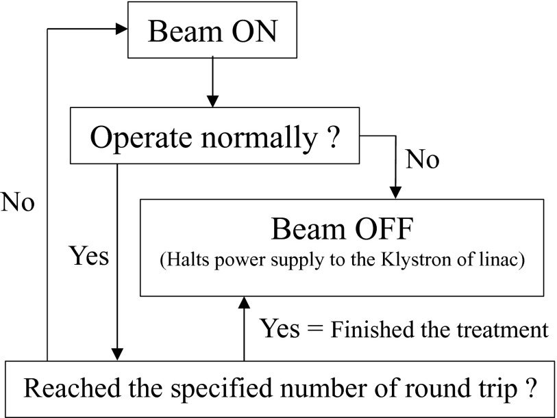
The motorized table that is generally used for total body irradiation (TBI) was modified for TSEB. The motorized table control unit can store arbitrary five speed patterns. The range of the speed that we can set is 5–40 mm/s. In this study, this table was moved at a constant speed. We performed at table speed with mentioned value in below with synchronizing only control of the number of the round trips with the linear accelerator. Figure 1 shows the logical diagram of a motorized table control in relation to synchronization with the linear accelerator. Because we decided to terminate treatment during one round trip in each direction to shorten time, each field's MUs were calculated using the dose for one round trip. In this study, measurements in two different SSDs set in 170 cm and 180 cm were performed. Because there was a dose difference by SSD changing, we secured dose uniformity in a body surface by calculating the table speed ratio from a dose ratio.
FIG. 1.
The logical diagram of motorized table control. This flow diagram is to start as soon as starting the treatment. A signal of the beam-off obtained as one round-trip completion.
We selected 6 MeV, the lowest available electron beam energy from our linear accelerator using a Varian Trilogy linear accelerator (Varian Medical Systems, Palo Alto, CA, USA). The maximum dose depth was set at ∼5 mm, which is commonly used to treat superficial lesions. We used a compensating filter that consists of two layers of polystyrene, each 2 mm thick, on a 10 mm thick PMMA sheet. An overview and the detailed structure of the compensating filter are shown in Figs. 2(a) and 2(b), respectively. It was fabricated to be used with collimator turned at 90° position, because we did not want to widen cross-plane dose distribution. The compensating filter was set at the wedge filter level using a tray for TBI.
FIG. 2.
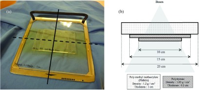
(a) is an overview of our compensating filter. Solid line indicates the in-plane direction. Dashed line indicates the cross-plane direction. (b) is the detailed structure of our compensating filter in plane. This filter was constructed using three PMMA layers of 1 cm and polystyrene of 0.2 cm. The densities of these materials were 1.2 g/cm3 and 1.03 g/cm3, respectively.
B. Patient setup and positioning
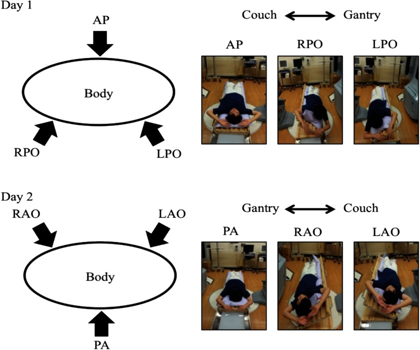
TSEB is required for treatment on a daily basis. Therefore, the patient setup needs to be simple, reproducible, and executable within a reasonable time. In addition, six directional irradiations were selected for securing dose uniformity (Fig. 3). For patient positioning, suction bags on an inclinable couch were prepared using four patterns for right-anterior oblique (RAO), right-posterior oblique (RPO), anterior-posterior (AP), and posterior-anterior (PA) irradiation. RAO and RPO were converted to left-anterior oblique (LAO) and left-posterior oblique (LPO), respectively, by reversing the head-to-foot direction. The patient's fingers were opened and hands were raised during treatment. We also used urethane sponges to support the open fingers. Also, Pb lenses and plate were used to shield the eyes and the nails of fingers and toes, respectively.
FIG. 3.
Six directional irradiations with an inclinable couch and suction bags are shown divided into Day1 and Day2. Day 1 in the upper figure was for AP, RPO, and LPO, and Day 2 in the lower figure was for RAO, PA, and LAO. At the right corner of each figure, a picture indicates the position in each irradiation direction.
C. Dose specification using motorized table and a compensating filter
In our TSEB technique, the dose on the surface of the skin was difficult to be measured using an inclinable couch on a motorized table. The percent depth dose (PDD) and off-centre ratio (OCR) were measured by the electron beams through the compensating filter. With regard to beam scatter conditions that involved a long SSD, measurements were made by positioning the solid phantom on the motorized table. PDD and OCR measurements were performed using a solid phantom (width × length: 30 cm × 30 cm). The reason why a water phantom was not used was to avoid undesirable fluctuation of the surface of the water when the motorized table was moved. Density of solid phantom is close to the polystyrene which is AAPM TG-30 recommended.1
PDD measurements were performed from surface to the depth of 5 cm. SSDs were set at 170 cm and 180 cm. OCR was measured at the dmax of PDD both in-plane and cross-plane. PDD and OCR measurements were made using a type 34045 plane parallel ionization chamber (PTW, Freiburg, Germany) and a type 30013 thimble ionization chamber (PTW, Freiburg, Germany), respectively. Measured surface dose value included contribution from the membranes of the ionization cavity anterior wall of plane parallel ionization chamber. The collimator settings were X1 = X2 = 7.5 cm and Y1 = Y2 = 20 cm. Because there is a limit of the movable range of the motorized table, vertex and a tiptoe might become the cold spot when we enlarge the position of X1 and X2. Radiation field was able to be arbitrarily set because we canceled the collimator interlock in maintenance mode.
In general, for absolute dose measurements using solid phantom, it is necessary to have depth-scaling factors (Cpl) equal to I50, W/I50, pl and fluence-scaling factors (hpl) that give the ratio of electron fluences at scaled depths. I50 is the depth in the material along the central axis in an electron beam at which the ionization chamber reading is 50% of its maximum value. For this study, Cpl was calculated from the measurement results. Although hpl is needed to correct the error at each depth, we thought that the error was sufficiently small and, therefore, we took into account this error for the overall TSEB treatment. Thus, we corrected the value that was extrapolated from the hpl that was calculated at the reference depth (dref) of various energies in solid phantom by Araki.10 The stopping power which is an important factor was also calculated from the equation of Burn et al.11 The correction factors of PTP, Ppol, and Pion were previously measured. Percentage depth ionization (PDI) was converted to PDD by multiplying various correction factors, which are mentioned above, and stopping power for quality of ionization. The conversion equation is the same as in AAPM TG-70,12
| (1) |
is the stopping-power. For the range of mean energies of TSEB electrons, the stopping-power values vary by ∼10%.1 R50 is the depth in the material along the central axis in an electron beam at which the absorbed dose is 50% of its maximum value. We underwent this procedure for each depth. The beam quality of E0 and Rp were also calculated. E0 and Rp were the mean energy of an electron beam at the surface of the phantom and the practical range of an electron beam, respectively. The equation of E0 mentioned by AAPM TG-301 is pointed out unfit for low and high energies.13 Therefore, we used the equation of AAPM TG-70.12 The X-ray contamination component of an electron beam gets absorbed farther downstream. We estimated this using a measurement at 5 cm in the solid phantom. The absolute dose measured while changing the motorized table speed with dose rate is 1000 MU/min. A motorized table speed was chosen as to deliver 2 Gy at dmax.
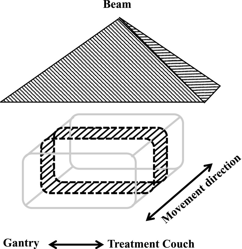
Planar dose uniformity was evaluated using EBT3 (International Specialty Products Inc., Wayne, United states) film positioned on a RT-3000-new (R-Tech Inc., Nagano, Japan) phantom. The EBT3 film was cut into a rectangular shape and was wrapped around the RT-3000-new (Fig. 4). The phantom was irradiated while moving the motorized table in six directions. We scanned the films 20 h after their irradiation using an Epson Expression 10000 XL scanner (Seiko Epson Corporation, Nagano, Japan) with 75 dpi resolution and extraction of the red component of the 48-bit RGB image. Dose distribution analysis was performed with a DD-system (R-Tech Inc., Nagano, Japan). Since this measurement was performed in the same manner as the actual treatment, scattered electrons from the inclined couch, a motorized table, the floor, and suction bag were considered as being measured by EBT3 film.
FIG. 4.
Schema of the measurement geometry for dose uniformity. The shaded area surrounded by the dashed line represents the EBT2 film on the RT-3000-new phantom. This phantom was irradiated in the position illustrated in Figure 3.
III. RESULTS AND DISCUSSION
A. Dose specification
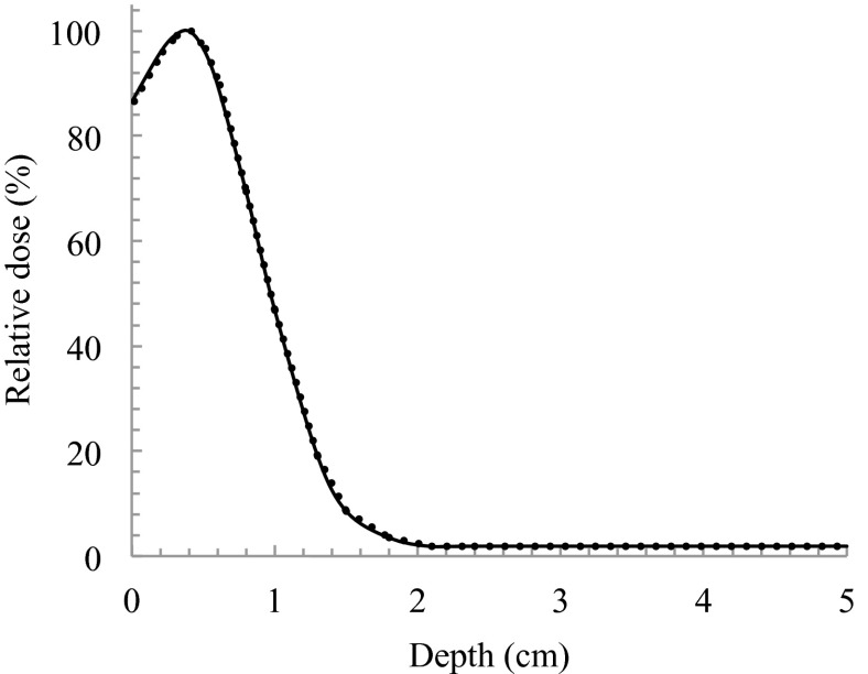
As shown in Fig. 5, PDD was measured in a solid phantom with and without a compensating filter. The values of dmax and R50 were 0.39 cm and 0.96 cm in both 170 cm and 180 cm of SSD, respectively. dref was calculated as 0.47 cm. While using a compensating filter, dmax was shifted to shallower depths by a distance of 1.1 cm. The beam quality of E0 and Rp were 2.7 MeV and 0.99 cm, respectively.
FIG. 5.
PDDs for SSDa of 170 cm and SSDb of 180 cm. Solid line and dashed line indicates the use of compensating filter at SSDs of 170 cm and 180 cm, respectively.
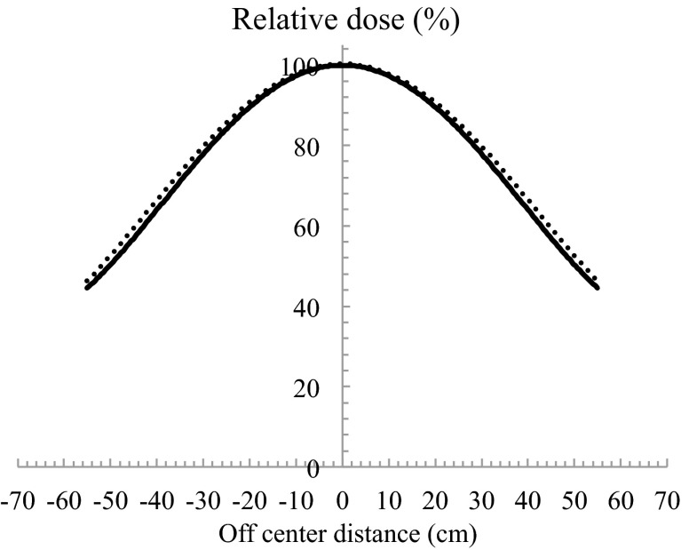
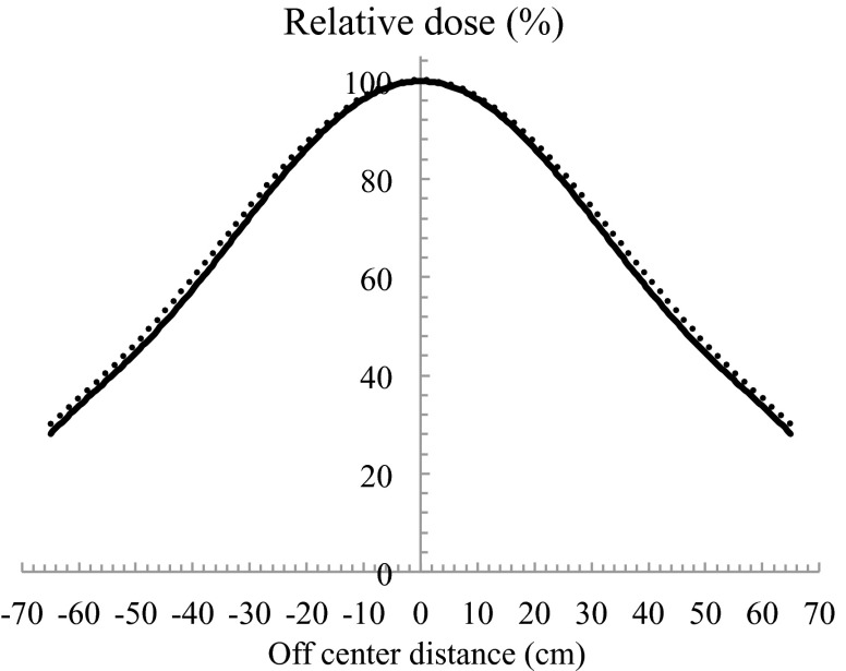
Using the configuration shown in Fig. 5, the relative 90% dose on the surface declined to 87% at a depth of 0.8 cm. The ideal electron beam for TSEB has dmax on a patient's surface, declines to 90% at a depth of a few millimetres, and has an X-ray contamination component of <1% beyond a depth of 2.0 cm.13 In most cases, for target lesions that are a few millimetres deep, the 90% dose should be at depth <1.0 cm. However, in cases when a target lesion is deeper, the compensating filter must be adapted. X-ray contamination was 2.2% of the dose at dmax (Fig. 5). The thicker compensating filter should not be used. OCR results of in-plane and cross-plane with using a compensating filter are shown in Figs. 6 and 7 at both SSDs, respectively. When SSD was extended, a slight spread in the relative dose distribution was observed. When using a compensating filter, the in-plane OCR was sufficient to irradiate the entire area of the skin in a patient. Although the cross-plane OCR was relatively higher in the off-centre direction, this was considered acceptable in the integrated distribution.
FIG. 6.
In plane OCRs for SSDa of 170 cm and SSDb of 180 cm. Solid line and dashed line indicates the use of compensating filter at SSDs of 170 cm and 180 cm, respectively. The minus shows Gantry direction, and the plus shows a couch direction.
FIG. 7.
Cross-plane OCRs for SSDa of 170 cm and SSDb of 180 cm. Solid line and dashed line indicates the use of compensating filter at SSDs of 170 cm and 180 cm, respectively.
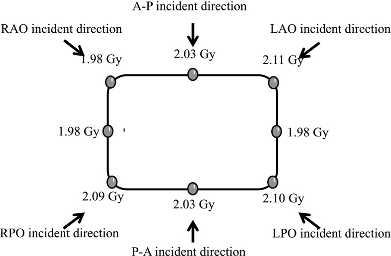
A dose calibration curve was previously obtained for analyzing the dose distribution. The results for dose uniformity are shown in Fig. 8. The patient surface dose was 2.04 ± 0.05 Gy and the error for the prescribed dose was ≤11%. As described in AAPM TG-30,1 we considered increasing the surface dose by adding the six fields. Considering that the buildup is eliminated by irradiation with multiple beams, we have been able to measure the correct value. The increase in surface dose is due to the energies of the lateral electron beams less than that on the central axis. Phantom positioning could be a factor of measurement uncertainty due to SSD alignment and phantom rotation. These are similar to issues that arise when treating actual patients.
FIG. 8.
Dose at each point on the phantom. The arrows show each incident direction.
B. Motorized table speed determination
In this study, motorized table speeds were chosen based on the absolute dose measurements. The motorized table speeds were determined using the following equation:
| (2) |
VSSDa and VSSDb were the velocities for SSDa and SSDb and A represents the speed correction factor given by the following equation:
| (3) |
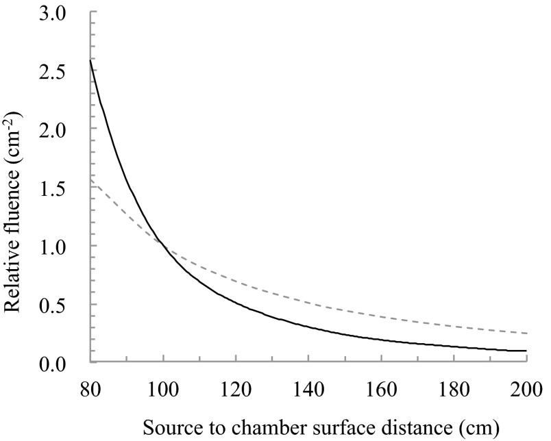
Using these equations, at angles AP and PA and four oblique angles, it does not require measurement at each SSD. For the same table speed with SSDa and SSDb being 170 cm and 180 cm, respectively, A was determined to be 1.192 by the absolute absorbed dose measurement. The difference in absolute dose of 19.2% was observed in 180 cm and 170 cm. Figure 9 shows the relative fluence normalized by 100 cm. This result did not match the inverse square law, the fluence was attenuated abruptly near the isocentre. In the distance that was used, the difference in relative fluence of 16.3% was observed in 180 cm and 170 cm (Fig. 9). It is considered that the difference of 19.2% as determined by absolute absorbed dose measurement resulted include errors of the coefficient factors. Furthermore, the dose pattern during one round trip of the motorized table movement was measured. Using the prescribed dose of 2 Gy, the required table speeds at SSDa and SSDb were calculated using Eqs. (2) and (3). Finally, the accurate motorized table speed at SSDa was determined by calculating the proportional value from the obtained value. We determined 20.0 mm/s at SSDa and 16.8 mm/s at SSDb as a result of calculation.
FIG. 9.
Theoretical value due to the inverse square law (dashed line) and relative fluence (solid line) normalized by 100 cm.
IV. CONCLUSION
We have proposed a new TSEB technique using an inclinable couch on motorized table and a compensating filter. We were shown treatment procedure and dosimetry results using these devices. Using this technique, each treatment field can be completed in a few minutes, without the patient maintaining an uncomfortable position for a long time. In addition, the burden on the patient is reduced because he has to lie down, and not stand. This technique can ensure the dose reproducibility because the patient is fixed in place using an inclinable couch on a motorized table. The dose uniformity is ∼≤11%. We suggested the method for the lesions of the skin surface. It was shown that we could provide treatment with good dosage uniformity without the burden on patients. However, the compensating filter we developed only covered lesions over a few millimetres. We may have to create a new filter for treating patients with deeper lesions.
REFERENCES
- 1.Karzmark C. J., Anderson J., Fessenden P., Svensson G., Buffa A., Khan F. M., and Wright K. A., “Total skin electron therapy: Technique and dosimetry,” AAPM Radiation Therapy Committee Task Group 30, Report No. 23, 1987.
- 2.Diamantopoulos S., Platoni K., Dilvoi M., Nazos I., Geropantas K., Maravelis G., Tolia M., Beli I., Efstathopoulos E., Pantelakos P., Panayiotakis G., and Kouloulias V., Phys. Med. 27(2), 62–68 (2011). 10.1016/j.ejmp.2010.09.001 [DOI] [PubMed] [Google Scholar]
- 3.Niroomand-Rad A., Gillin M. T., Komaki R., Kline R. W., and Grimm D. F., Int. J. Radiat. Oncol., Biol., Phys. 12, 415–419 (1986). 10.1016/0360-3016(86)90361-5 [DOI] [PubMed] [Google Scholar]
- 4.El-Khatib E., Hussein S., Nikolic M., Voss N. J. S., and Parsons C., Int. J. Radiat. Oncol., Biol., Phys. 33, 469–474 (1995). 10.1016/0360-3016(95)00112-C [DOI] [PubMed] [Google Scholar]
- 5.Williams P. C., Hunter R. D., and Jackson S. M., Br. J. Radiol. 52, 302–307 (1979). 10.1259/0007-1285-52-616-302 [DOI] [PubMed] [Google Scholar]
- 6.Tetenes P. J. and Goodwin P. N., Radiol. 122, 219–226 (1977). [DOI] [PubMed] [Google Scholar]
- 7.Leer J. W. H., Broerse J. J., De Vroome H., Chin A., Noordijk E. M., and Dutreix A., Radiother. Oncol. 18, 10–15 (1990). 10.1016/0167-8140(90)90174-U [DOI] [PubMed] [Google Scholar]
- 8.Deufel C. L. and Antolak J. A., J. Appl. Clin. Med. Phys. 14(5), 115–126 (2013). 10.1120/jacmp.v14i5.4309 [DOI] [PMC free article] [PubMed] [Google Scholar]
- 9.Luĉić F., Sánchez-Nieto B., Caprile P., Zelada G., and Goset K., J. Appl. Clin. Med. Phys. 14(5), 1–12 (2013). 10.1120/jacmp.v14i5.4388 [DOI] [PMC free article] [PubMed] [Google Scholar]
- 10.Araki F., Med. Phys. 34, 4368–4377 (2007). 10.1118/1.2790840 [DOI] [PubMed] [Google Scholar]
- 11.Burns D. T., Ding G. X., and Rogers D. W. O., Med. Phys. 23, 383–388 (1996). 10.1118/1.597893 [DOI] [PubMed] [Google Scholar]
- 12.Gerbia B. J., Antolak J. A., Deibel F. C., Followill D. S., Herman M. G., Higgins P. D., Huq M. S., Mihailidis D. N., Yorke E. D., Hogstrom K. R., Rouge B., and Khan F. M., Med. Phys. 36, 3239–3278 (2009). 10.1118/1.3125820 [DOI] [PubMed] [Google Scholar]
- 13.Rogers D. W. O. and Bielajew A. F., Med. Phys. 13, 687–694 (1986). 10.1118/1.595831 [DOI] [PubMed] [Google Scholar]


